I'm not exactly sure about the practical value of implementing
this design, but because it looks very different from everything
else I have seen so far, I felt a need to mention it.
Note, that this article only gives you a simplified concept about
what things really may look like.
And that I'm using a different notation from the original description.
The original description (available at Bitsavers) is written
like one of them boring scientific publications, be warned.
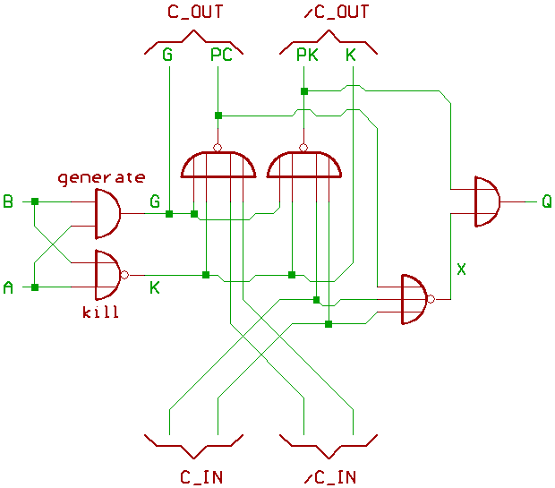
One adder cell:
G (generate) generates a carry if A=1 and B=1.
PC (propagate carry) propagates a carry from the previous Bit
if A=1 or B=1.
K (kill) indicates, that A=0 and B=0, and that no carry
comes out of the adder cell regardless of the carry input.
PK (propagate kill) says that no carry propgates through
from the previous Bit.
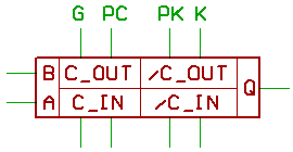
Now to pack the adder cell schematic into a cute little box:
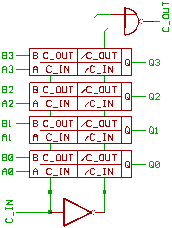
And to connect four Boxes for building a 4 Bit adder.
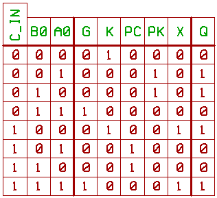
Logic signals at the Q0 adder:
An idea for a fast lookahead carry.
The original text calls this a "leap frog" carry chain.
Note the signals LFK (leap frog kill) and LFC (leap frog carry).
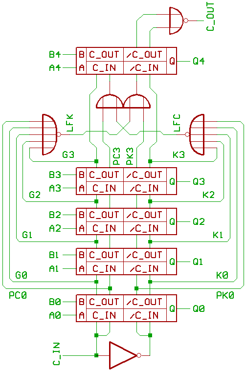
And yes, I did draw this a bit different from the original text.
The two_input OR gates only are drawn to simplify things,
you could replace the four_input NOR gates inside the Q3 adder
by five_input NOR gates for getting rid of said OR gates.
Would be interesting to find out what takes less logic gates:
Building a 74182 based fast lookahead carry adder...
or building a fast adder "the Bendix way".
[HOME] [UP]/ [BACK] [1] [2] [3] [4] [5] [6] [7] [8] [NEXT]
(c) Dieter Mueller 2012