**Open research on three-dimensional linear optical transforms written with a femtosecond laser inside a fused-silica cube, and on the path from simulation to a first fabricated neural-network prototype.**







[Overview](#overview) · [Verified results](#verified-positive-numerical-results) · [FEMTO-1 prototype plan](#femto1) · [Scientific closure](#scientific-closure-20261013) · [Graphics lab](#lab-20261009) · [How it works](#how-it-works-in-8-gifs) · [Results](#results-to-date) · [Reproduce](#reproduce) · [Method](#method-and-collaboration) · [Roadmap](#roadmap)
---
## Overview
The idea is to write **waveguides, couplers and phase elements** inside a block of fused silica with a femtosecond laser, so that the geometry of the glass itself performs a linear optical transform of the light passing through it. The long-term goal is a neural network whose trained weights are compiled into fabricable geometry (gaps, lengths, depths) and "printed" into glass: **the model becomes the geometry**.
This repository does **not** present a finished processor. It links geometry and material properties to verifiable calculations, first in simulation and then, where the evidence allows, in a fabricable design. Every claim is tied to a preregistered protocol and hashed evidence, and failed tests are kept.
| Where the project stands (13 October 2026) | |
|---|---|
| Physics and scaling | Preregistered kill tests completed (T24–T30). See the [scientific closure](#scientific-closure-20261013). |
| Graphics-engine laboratory | Calibrated GPU rasterization of complex optical fields in Blender (OpenGL and Vulkan). See the [lab section](#lab-20261009). |
| Next milestone | **FEMTO-1**, a first passive glass chip that classifies light patterns, designed to be fabricated by femtosecond laser writing. See the [prototype plan](#femto1). |
| Fabricated or measured device | **None yet.** |
### Verified positive numerical results
The project has working numerical components and measured digital-simulation acceleration. These results remain approved within their stated scope; later negative experiments do not replace them.
| Positive result | Verified evidence | Scope |
|---|---|---|
| CUDA128 acceleration | CPU median **2.4528 s** versus resident CUDA128 median **0.10982 s**: **22.33× faster**, with three recorded hot repetitions | One scalar SSFM propagation case, not complete-network inference or an energy measurement. [Original timings and retained arrays](Docs/GLASS-GPU-2026-10-05-RESULTS.md) |
| CUDA numerical equivalence and local refinement | Four complex128 equivalence cases and eight further local cases pass their registered criteria | CPU/GPU wave-field parity and bounded stability; the four complex64 failures remain separate. [Results](Docs/GLASS-GPU-2026-10-05-RESULTS.md) |
| Graphics-engine complex fields | **168/168** P2 fields pass in OpenGL and Vulkan, including constructive, destructive and quarter-phase superposition; maximum error **5.86×10⁻⁷ ≤ 5×10⁻⁶** | Actual Blender rasterization and coherent field representation. [Independent audit and costs](Docs/POINT-03-RENDER-P3-ANALYTIC-RESULTS.md) |
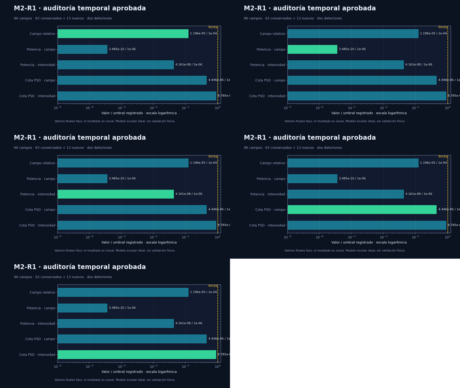
| C2 / M2 temporal consistency | Both stages pass their five temporal criteria; M2's intensity indicator is **8.78×10⁻⁶ ≤ 10⁻⁵** | Audited discrete scalar solutions; spatial and domain closure remain separate. [M2 evidence](Docs/POINT-03-D16-M2-RESULTS.md) |
Potential device-energy and latency advantages are evaluated separately in the [FEMTO-1 plan](#femto1). They are conditional model predictions, including the positive fan-out scenarios, and have not yet been measured on a fabricated optical processor.
> **Historical context.** Microsoft's Project Silica ([official page](https://www.microsoft.com/en-us/research/project/project-silica/)) demonstrates volumetric **storage** in glass, not optical processing. It is neither a replica of this work nor evidence in its favour.
---
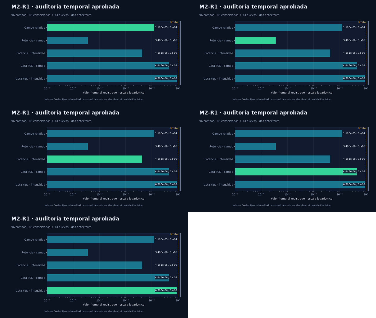 Each bar is a fixed final value divided by its threshold, on a logarithmic scale. The highlight moves to aid reading; **it does not represent temporal propagation or new data**. The PSD bound is the registered numerical indicator, not a guarantee on the continuous error.
### Graphics engine: calibrating the GPU readout too
Each bar is a fixed final value divided by its threshold, on a logarithmic scale. The highlight moves to aid reading; **it does not represent temporal propagation or new data**. The PSD bound is the registered numerical indicator, not a guarantee on the continuous error.
### Graphics engine: calibrating the GPU readout too
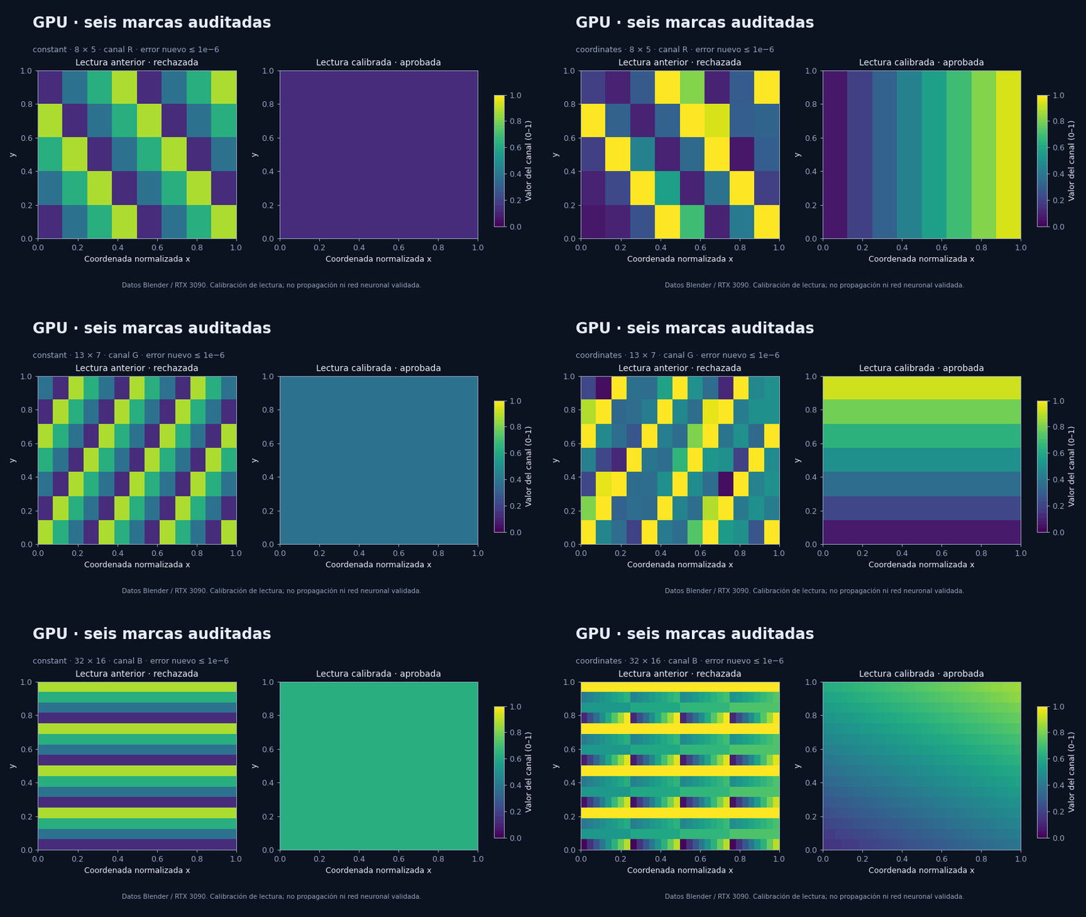
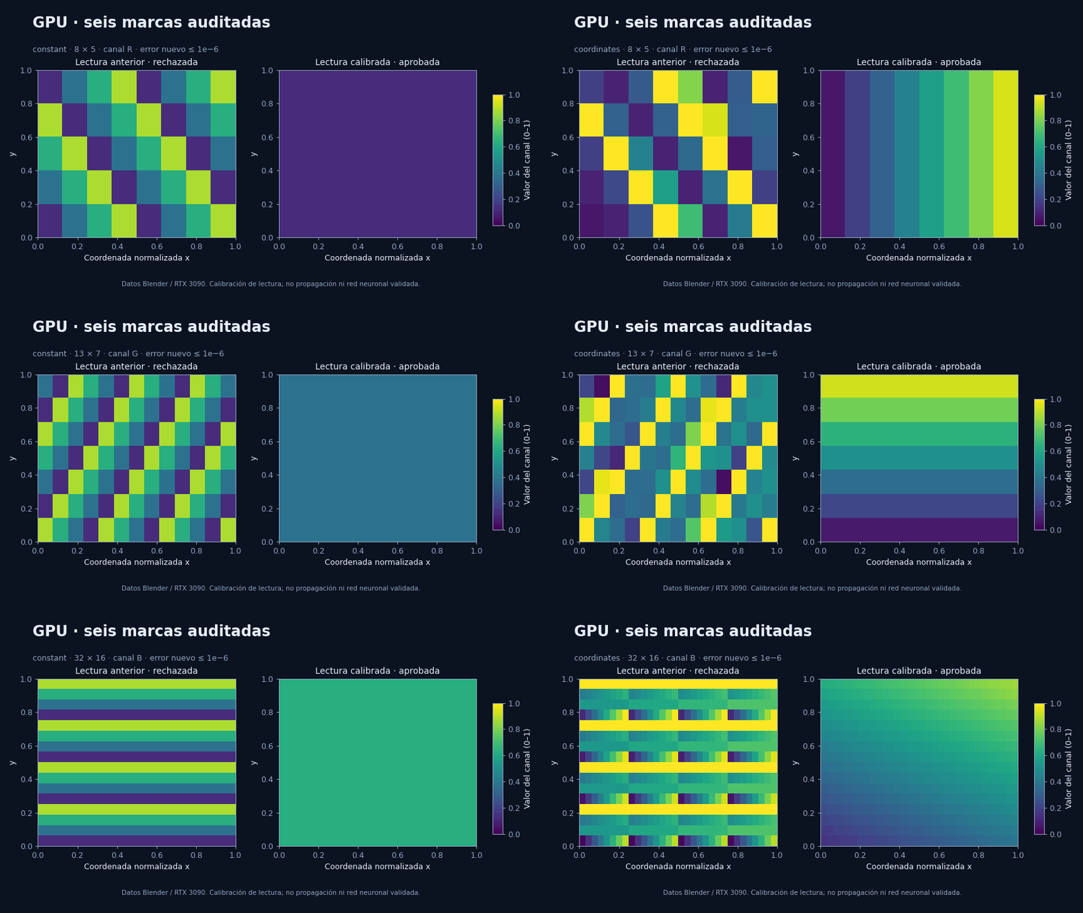 3D triangles, rasterization, shaders and an FP32 framebuffer were run in Blender 4.5.14/OpenGL on an RTX 3090. Independent calibration detected and corrected the buffer interpretation. The six new cases passed; the 84 earlier P2 results remain negative. A readout calibration **is not a validated neural network**. All timings, including start-up and readout, are kept. No general speed or energy advantage has been demonstrated.
### OpenGL and Vulkan: precision of graphics coordinates
3D triangles, rasterization, shaders and an FP32 framebuffer were run in Blender 4.5.14/OpenGL on an RTX 3090. Independent calibration detected and corrected the buffer interpretation. The six new cases passed; the 84 earlier P2 results remain negative. A readout calibration **is not a validated neural network**. All timings, including start-up and readout, are kept. No general speed or energy advantage has been demonstrated.
### OpenGL and Vulkan: precision of graphics coordinates
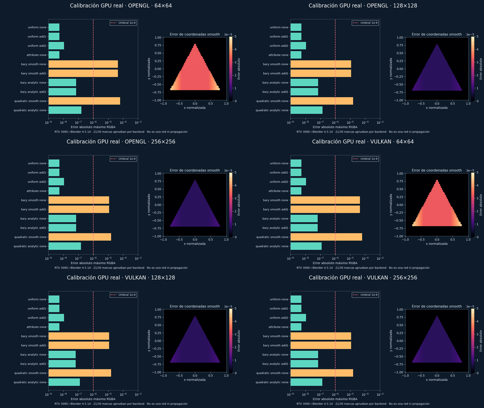 Each backend passes 21 marks and retains nine failures. Coordinates computed in the fragment shader pass; those interpolated by smooth shading fail. This is a real calibration of the graphics instrument, without a functional network or optical propagation.
[Data, costs and results](Docs/POINT-03-RENDER-PIPELINE-RESULTS.md) ·
[Generator](tools/gif_pipeline_calibration_20261009.py) ·
[Manifest](resultados/codex/point03_pipeline_gif_manifest_20261009.json).
### P2 complex fields: rasterization and superposition audited
Each backend passes 21 marks and retains nine failures. Coordinates computed in the fragment shader pass; those interpolated by smooth shading fail. This is a real calibration of the graphics instrument, without a functional network or optical propagation.
[Data, costs and results](Docs/POINT-03-RENDER-PIPELINE-RESULTS.md) ·
[Generator](tools/gif_pipeline_calibration_20261009.py) ·
[Manifest](resultados/codex/point03_pipeline_gif_manifest_20261009.json).
### P2 complex fields: rasterization and superposition audited
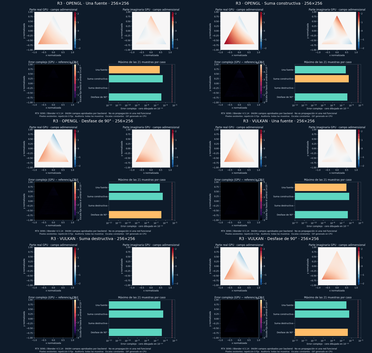
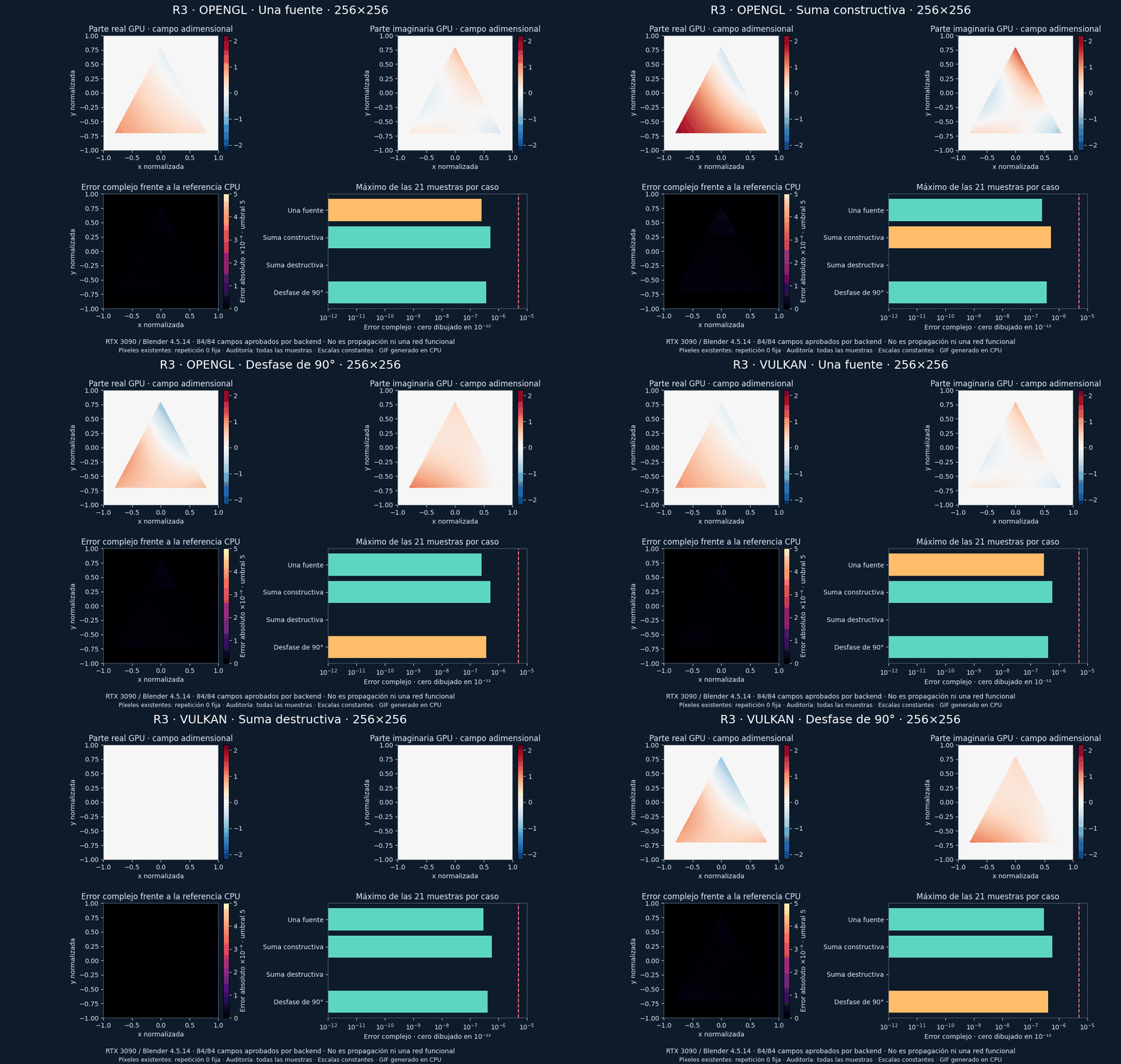 OpenGL and Vulkan pass all 84 fields of each trial, including constructive and destructive sums and a 90° phase shift. The 3D triangles are rasterized; the fragment shader computes the complex field, and the coherent sum preserves its phase. The GIF shows already-computed pixels, with a constant scale and a fixed zero repeat. The bars include the 21 samples of each case.
This is a manufactured P2 representation bench, without guided propagation or a functional network. All preparation, start-up, drawing and readout costs are published, and no general or energy advantage has been demonstrated.
[168 raw fields, audits and costs](Docs/POINT-03-RENDER-P3-ANALYTIC-RESULTS.md) ·
[Generator](tools/gif_p3_analytic_v2_20261009.py) ·
[Manifest](resultados/codex/point03_p3_gif_manifest_v2_20261009.json).
### Architecture of the network we want to test
OpenGL and Vulkan pass all 84 fields of each trial, including constructive and destructive sums and a 90° phase shift. The 3D triangles are rasterized; the fragment shader computes the complex field, and the coherent sum preserves its phase. The GIF shows already-computed pixels, with a constant scale and a fixed zero repeat. The bars include the 21 samples of each case.
This is a manufactured P2 representation bench, without guided propagation or a functional network. All preparation, start-up, drawing and readout costs are published, and no general or energy advantage has been demonstrated.
[168 raw fields, audits and costs](Docs/POINT-03-RENDER-P3-ANALYTIC-RESULTS.md) ·
[Generator](tools/gif_p3_analytic_v2_20261009.py) ·
[Manifest](resultados/codex/point03_p3_gif_manifest_v2_20261009.json).
### Architecture of the network we want to test
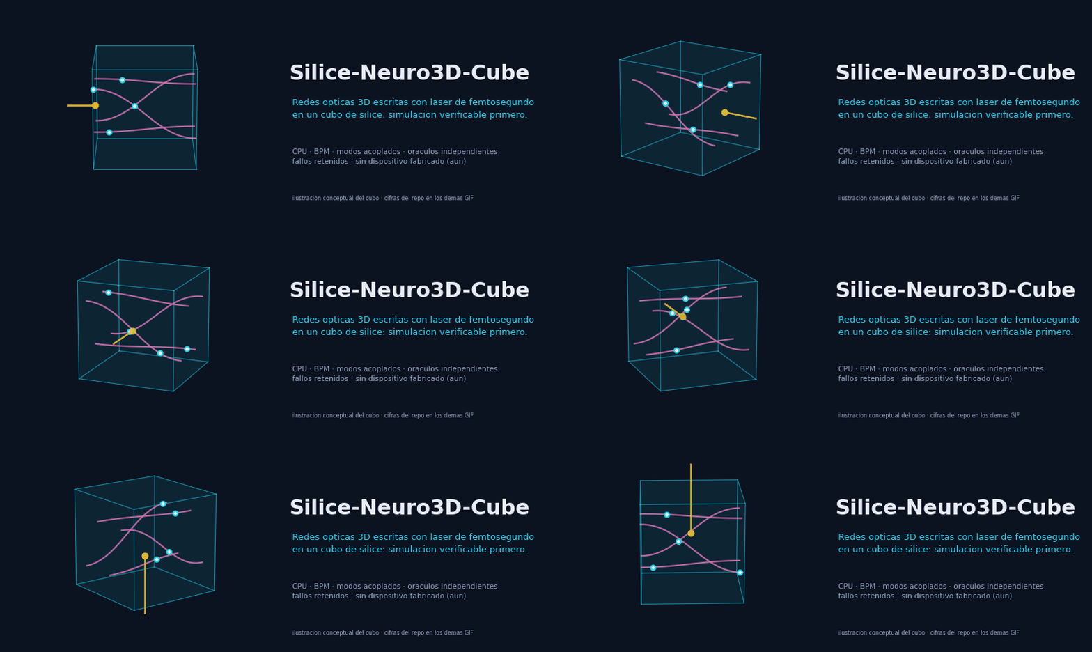
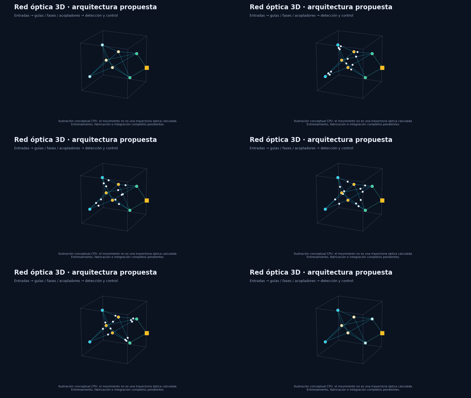
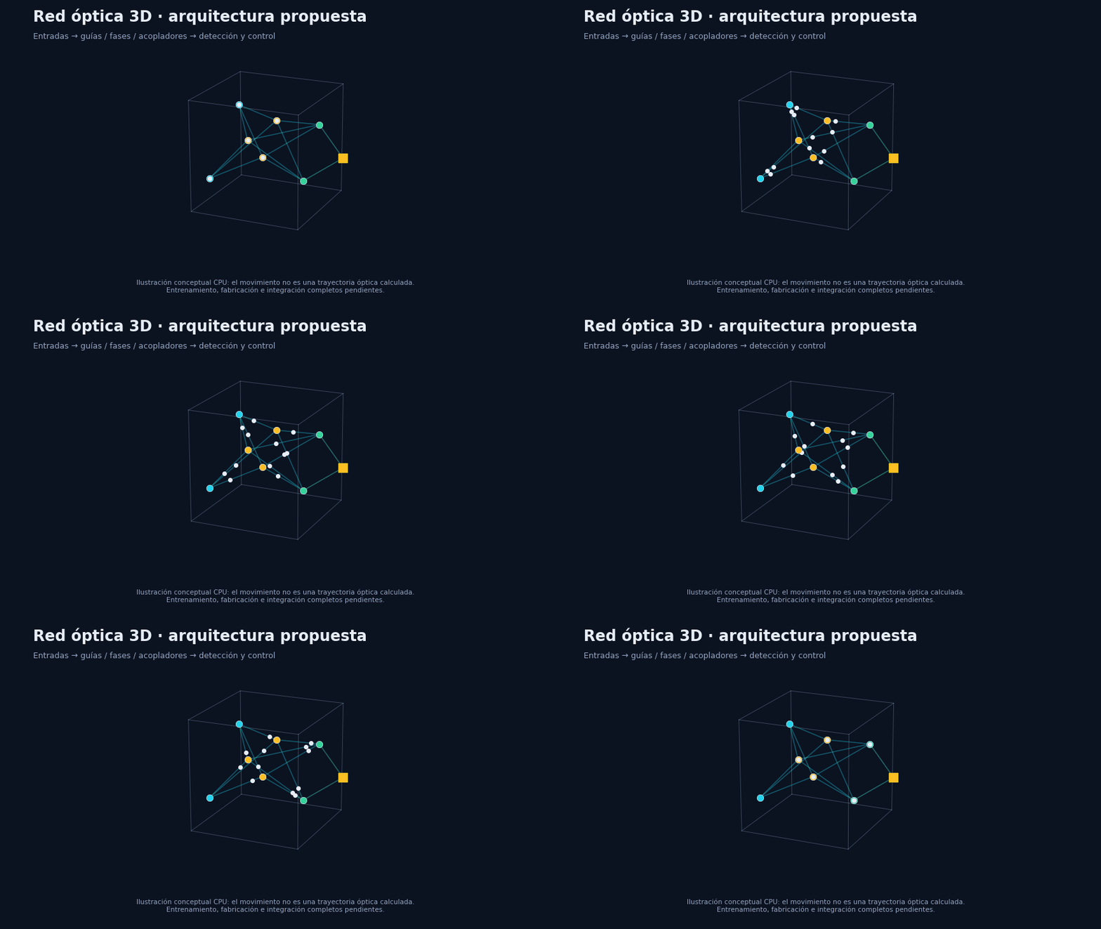 **Conceptual CPU illustration, labelled in every frame.** The dots show the proposed flow; they do not claim computed optical trajectories. The passive network is linear in field. Detection, nonlinearity and control must be declared and validated as part of the complete system. The [FEMTO-1 plan](#femto1) is the first concrete, fabricable instance of this architecture.
The animations are produced by [the reproducible generator](tools/gif_scientific_snapshot_20261009.py).
[Manifest of inputs, versions and hashes](resultados/codex/point03_readme_gif_manifest_v2_20261009.json).
**Conceptual CPU illustration, labelled in every frame.** The dots show the proposed flow; they do not claim computed optical trajectories. The passive network is linear in field. Detection, nonlinearity and control must be declared and validated as part of the complete system. The [FEMTO-1 plan](#femto1) is the first concrete, fabricable instance of this architecture.
The animations are produced by [the reproducible generator](tools/gif_scientific_snapshot_20261009.py).
[Manifest of inputs, versions and hashes](resultados/codex/point03_readme_gif_manifest_v2_20261009.json).
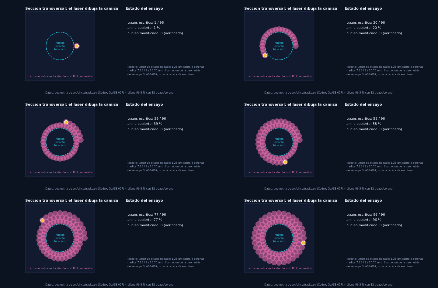 An unmodified silica core is surrounded by **reduced-index tracks** (depressed cladding). Here, three rings of 1.25 µm discs (GLASS-007 geometry). With 32 tracks per ring the annulus is 95 % filled; with 16, 69 %.
### 2 · Does the cladding hold the light?
An unmodified silica core is surrounded by **reduced-index tracks** (depressed cladding). Here, three rings of 1.25 µm discs (GLASS-007 geometry). With 32 tracks per ring the annulus is 95 % filled; with 16, 69 %.
### 2 · Does the cladding hold the light?
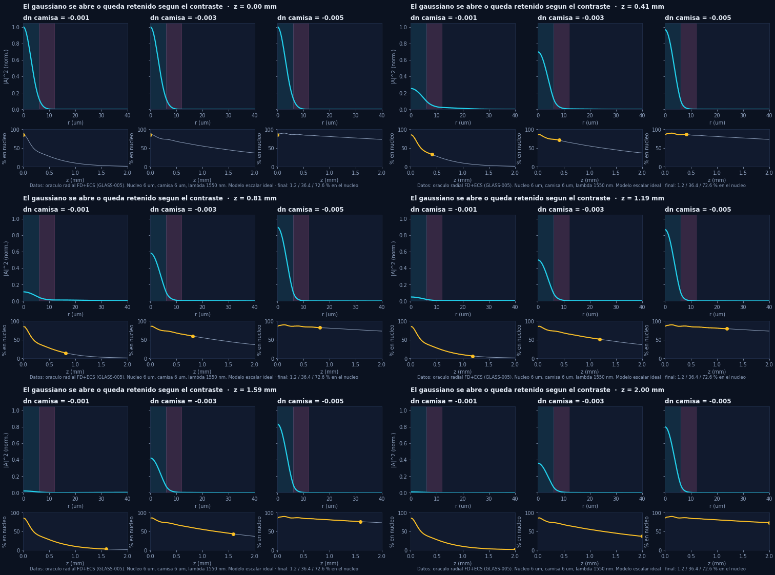 A beam propagates 2 mm. With weak contrast (δn = −0.001) it spreads; with δn = −0.005 it stays mostly in the core (1.2 % / 36.4 % / 72.6 %). Result of a radial solver independent of the BPM. **Ideal scalar model**, not a measured guide.
### 3 · Leakage falls exponentially with thickness
A beam propagates 2 mm. With weak contrast (δn = −0.001) it spreads; with δn = −0.005 it stays mostly in the core (1.2 % / 36.4 % / 72.6 %). Result of a radial solver independent of the BPM. **Ideal scalar model**, not a measured guide.
### 3 · Leakage falls exponentially with thickness
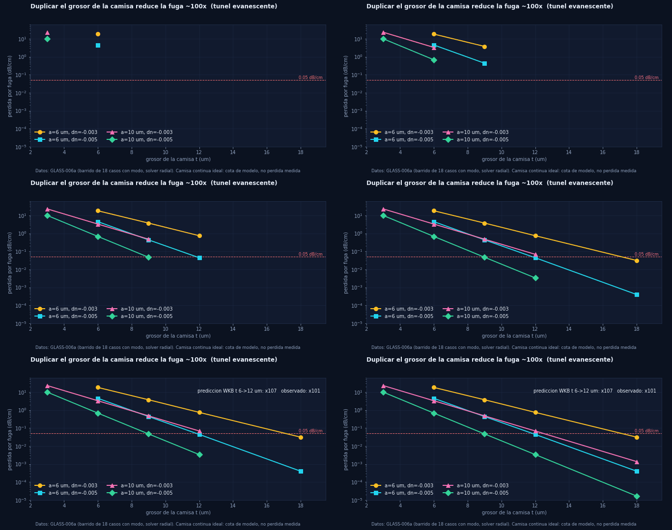 The mode is *quasi-bound*: it tunnels out through the cladding. Doubling the thickness reduces leakage about 100×, and the WKB prediction fixed before measuring holds (×107 predicted, ×101 observed). With a 6 µm core and δn = −0.005, about 12 µm of continuous cladding gives 0.044 dB/cm **in the model**.
### 4 · A coupler mesh computes a transform
The mode is *quasi-bound*: it tunnels out through the cladding. Doubling the thickness reduces leakage about 100×, and the WKB prediction fixed before measuring holds (×107 predicted, ×101 observed). With a 6 µm core and δn = −0.005, about 12 µm of continuous cladding gives 0.044 dB/cm **in the model**.
### 4 · A coupler mesh computes a transform
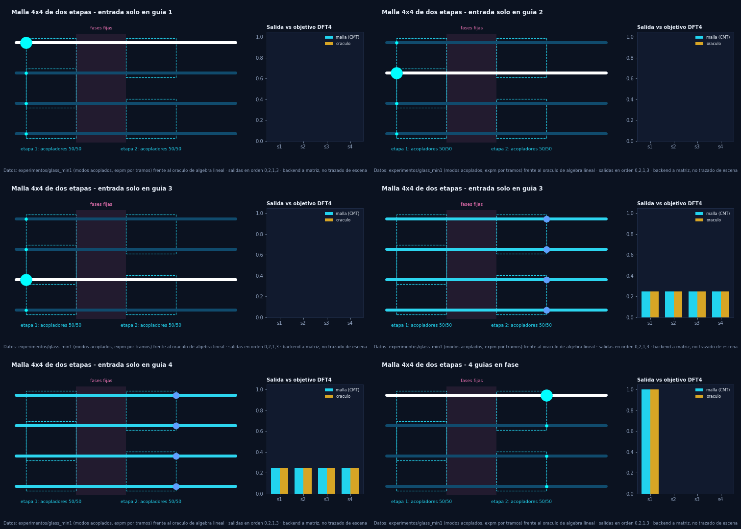 Two stages of 50/50 couplers with fixed phases perform a 4-point DFT. The oracle is pure linear algebra; the simulator integrates coupled modes piecewise. **Matrix backend**, labelled as such: it is not a trace of the scene.
### 5 · The mean misleads: what matters is 95 % of the parts
Two stages of 50/50 couplers with fixed phases perform a 4-point DFT. The oracle is pure linear algebra; the simulator integrates coupled modes piecewise. **Matrix backend**, labelled as such: it is not a trace of the scene.
### 5 · The mean misleads: what matters is 95 % of the parts
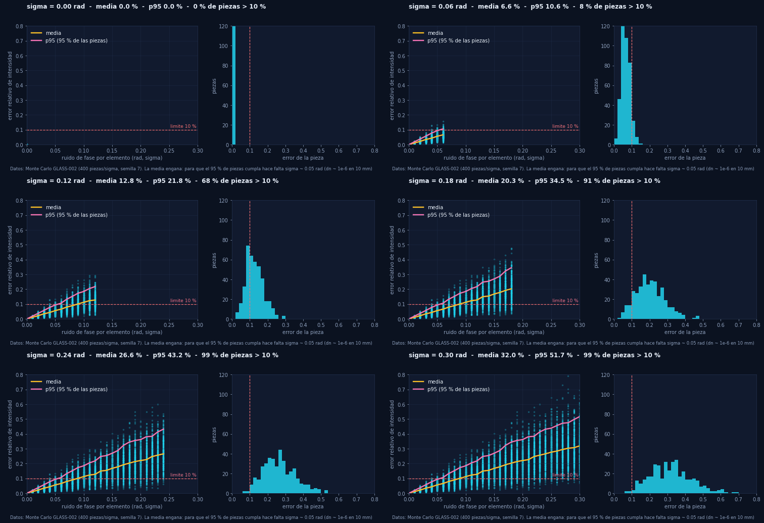 With phase noise σ = 0.10 rad the *mean* error is about 11 %, but more than half of the parts exceed 10 %. For 95 % of parts to comply, σ ≈ 0.05 rad is needed, i.e. δn ≈ 10⁻⁶ over 10 mm. That is why a coherent design needs **post-write trimming or heaters**, and why FEMTO-1 is incoherent.
### 6 · Fewer tracks, more leakage (and gaps hurt)
With phase noise σ = 0.10 rad the *mean* error is about 11 %, but more than half of the parts exceed 10 %. For 95 % of parts to comply, σ ≈ 0.05 rad is needed, i.e. δn ≈ 10⁻⁶ over 10 mm. That is why a coherent design needs **post-write trimming or heaters**, and why FEMTO-1 is incoherent.
### 6 · Fewer tracks, more leakage (and gaps hurt)
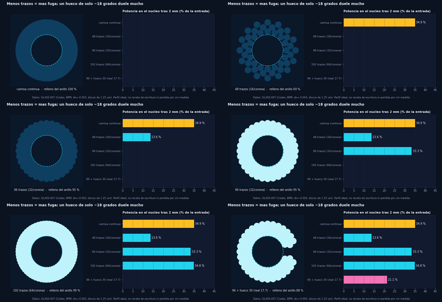 96 tracks approach the continuous cladding (33 % vs 35 % in GLASS-007; with the corrected observable and index, GLASS-009d, 33.2 % vs 36.3 %, about 8 % less). 48 tracks lose more than half. A nominal 30° gap actually opens 17.7° and sinks the power. Data from the GLASS-007 BPM.
### 7 · Two independent solvers
96 tracks approach the continuous cladding (33 % vs 35 % in GLASS-007; with the corrected observable and index, GLASS-009d, 33.2 % vs 36.3 %, about 8 % less). 48 tracks lose more than half. A nominal 30° gap actually opens 17.7° and sinks the power. Data from the GLASS-007 BPM.
### 7 · Two independent solvers
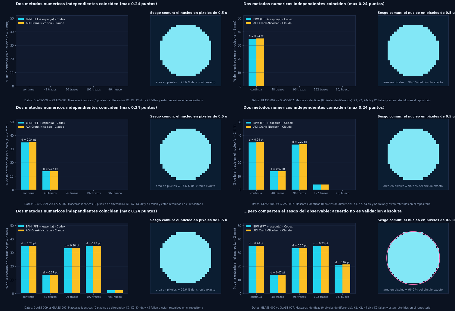 An FFT BPM and an ADI Crank–Nicolson finite-difference solver agree within ≤ 0.24 points on five profiles with identical masks. **However**, they share an observable bias (the core on 0.5 µm pixels covers 96.6 % of the exact area), and several method controls **fail**. Those failures are retained.
### 8 · Method: contract, execution, audit, retained failures
An FFT BPM and an ADI Crank–Nicolson finite-difference solver agree within ≤ 0.24 points on five profiles with identical masks. **However**, they share an observable bias (the core on 0.5 µm pixels covers 96.6 % of the exact area), and several method controls **fail**. Those failures are retained.
### 8 · Method: contract, execution, audit, retained failures
 Every trial is frozen **before** measuring. Failures are neither hidden nor relaxed: they are published together with their cause.
## Results to date
Current status: [ESTADO-ACTUAL](Docs/ESTADO-ACTUAL.md). The [current inventory](Docs/PROJECT-STATUS.md) separates execution, approved criteria, failures and limits. Earlier reports and GIFs keep their dates and versions; they are not reinterpreted as device measurements.
| Milestone | Documented result | Status and limit |
|---|---|---|
| CPU environment | Isolated install, six pinned versions, 51 tests run | PASS on Windows 10 / Python 3.13.7; [report](Docs/POINT-01-RESULTS.md) |
| GLASS-001/002 | Feasibility and ideal DFT4 intensity implementation | CMT model; output phases and mean/p95 difference explicit |
| GLASS-003 V1/V2 | Balance and scalar propagation; V2 has 15 cases | Original failures kept; −0.005 fails domain and dz |
| GLASS-004 | CMT versus analytic couplers | Nominal/controls PASS; field error ≈ 2e-16; hypothetical noise |
| GLASS-005 | Radial m = 0 reference and longitudinal-step diagnosis | Selected cases; SK1310 recipe and measurements pending |
| GLASS-006a | 20 geometries, 18 selected modes | G2: 7 PASS / 11 FAIL; two cases without a selected mode |
| GLASS-006b | Coupler pilot run: 12 CPU cases | Linearity/symmetry and partial controls PASS; dx and Gaussian reduction FAIL |
| GLASS-007 V1/V2 | Discrete tracks; V2 with coverage and partial detector | V2: 13 cases and own criteria PASS; boundary/global pending |
| GLASS-008/009 | Geometry and a second ADI propagator | Partial agreement; historical K1/K2/K4-dx/K5 kept |
| GLASS-009b/d | Observable correction and coverage profile | P3 of 009b and Q4 of 96 tracks of 009d still FAIL |
| GLASS-009c | Run: complex field in vacuum, including phase | Partial validation by angle, domain and distance; isolated reflection pending |
| GLASS-010 | Six cases and 24 M4 comparisons approved | Does not resolve the whole 006a sweep; mode/remainder interference needs correction |
| GLASS-GPU-001 | Eight CUDA outputs compared with CPU | Four complex128 PASS and four complex64 FAIL |
| GLASS-GPU-001 timing | CPU median 2.4528 s / resident CUDA128 median 0.10982 s = **22.33×** | Measured digital-simulation acceleration for one hot scalar propagation case; three repetitions, not full-network inference or an energy measurement. [Original report](Docs/GLASS-GPU-2026-10-05-RESULTS.md) |
| GLASS-GPU-002 | Eight additional complex128 cases | Local criteria PASS; no global convergence or independent ADI contrast |
| MEGA-001 | 24 affine hits and four analytic CPU criteria | Diagnostic PASS; Vulkan metadata is not RT execution |
Details in [`Docs/`](Docs/), [`coordinacion/respuestas/`](coordinacion/respuestas/) and [`resultados/`](resultados/).
The [independent V2 replication](Docs/GLASS-007-V2-RESULTS.md) confirms that 96 tracks retain 8.5 % less power in the core than the continuous cladding. The same replication separates the effect of averaging the index from that of the detector. The earlier GIFs keep V1 data; they are not V2 figures. Boundary, global convergence and fabrication have not been certified. Both of our own writing failures are kept alongside the hash-based continuation, without repeating four valid cases.
### What the repository does **not** demonstrate
- No real waveguide. The profiles are ideal: scalar, paraxial, without polarization, reflection, bends, roughness or stress.
- No measured loss per cm. The continuous ring is a model reference, not a universal bound.
- No fabricated neural network. A passive mesh is **linear in field**; nonlinearity, detection and electronics sit outside the cube and must be declared separately. FEMTO-1 is a plan, not a device.
- No measured speed or efficiency advantage over other networks. The GPU comparison in the [FEMTO-1 section](#femto1) is a parametric model.
## Repository structure
```
Silice-Neuro3D-Cube/
├── src/silice/ library (7 modules): bpm.py (scalar paraxial BPM), tracks.py (discrete
│ tracks), coupler.py (CMT coupling), coverage.py (partial area and
│ coverage), gpu_bpm.py and gpu_refinement.py (bounded CUDA trials) [Codex]
├── tests/ CPU tests [Codex]
├── scripts/ trials, audits, verification (check.py) [Codex]
├── experimentos/ Claude's milestone trials (glass_*, t2x_*, neurocubo_blender_claude) [Claude]
├── agentkit/ closure kit: preregistration, statistics, limits, metrology (61 tests)
├── tools/ generators of the README GIFs from the data
├── assets/ README GIFs and header
├── resultados/ JSON reports with parameters, hashes and criteria (retained evidence)
├── paper/ manuscript and full paper for review
├── Docs/ contracts, results, reviews, status and closure reports
├── coordinacion/ checkpoint, board, queue, responses and agent tasks
├── .github/ CI: CPU tests on Windows and Linux, blob-size guard
├── requirements/ hash-pinned dependency locks
├── pyproject.toml silice-neuro3d-cube package metadata
└── AGENTS.md collaboration and review rules between agents
```
## Reproduce
The reproducible CPU install uses Windows 10 x64 and CPython 3.13.7. A validated Linux path (Ubuntu 24.04, CI on GitHub Actions) is described in [CPU-REPRODUCTION](Docs/CPU-REPRODUCTION.md#linux-ci-validated-path). From the repository root:
```powershell
& 'C:\Python313\python.exe' scripts/bootstrap_cpu.py
```
The command installs six dependencies with pinned versions and hashes into `.venv`, installs the package and runs the full environment check. Instructions and an offline option are in [CPU-REPRODUCTION](Docs/CPU-REPRODUCTION.md).
To repeat the check without reinstalling, or to run only the 51 current CPU tests:
```powershell
& '.\.venv\Scripts\python.exe' scripts/verify_environment.py
& '.\.venv\Scripts\python.exe' -B scripts/check.py
```
The check produces fresh reports, verifies the hashes of the historical evidence and limits each numerical process to one thread and 40 seconds. It includes the tests, the CMT audit, the GLASS-007 V2 audit and the 15 GLASS-003 V2 cases. The scientific convergence failure of GLASS-003 V2 must be reproduced with complete results and correct balances; it does not become an approved convergence. Each trial's historical instructions keep their own scope and limits. This install does not run the GPU or Blender.
## Method and collaboration
Read the [research contract](Docs/RESEARCH-CONTRACT.md), the [checkpoint](coordinacion/CHECKPOINT.md) and the [board](coordinacion/TABLON.md). Codex and Claude have independent tasks and review each other's evidence. **JEV does not count as consulted without `provenance=jev`.** The earlier `9_NEBULA_NEW` project is left intact.
Rules:
- Contract before measuring.
- Thresholds are never relaxed afterwards.
- Failures are retained.
- Visualization, mathematical model, simulation and physical device are always kept distinct.
- No GPU or Blender load without a window and an exclusive reservation.
- No contact, purchase or data agreement with any laboratory or foundry without the owner's explicit approval.
Authorship, roles and use of AI: [CONTRIBUTORS.md](CONTRIBUTORS.md). How to cite the repository: [CITATION.cff](CITATION.cff).
## Roadmap
Status as of 13 October 2026. Detail and evidence for each item: [claims ledger](Docs/CIERRE-20261012/CLAIMS-TABLE-20261013b.md) and [`Docs/CIERRE-20261012/`](Docs/CIERRE-20261012/).
**Done (closure guide v2)**
- [x] Closure kit [`agentkit/`](agentkit/), identical to the guide, with 61 tests on Windows and Linux (CI)
- [x] Preregistered kill tests: 3D vs planar depth and crossings (T25), in-situ calibration in a model (T27), energy per operation (T24, **negative result**) and state of the art with 31 verified references (T26)
- [x] Trench-guide design (T20D) and H1 amendment A1, dated before measuring
- [x] Adversarial review (T30) and corrected central claim (delimitation, not novelty)
- [x] Ledger of 41 claims, short manuscript and [full paper for review](paper/full/paper.pdf)
- [x] [Apache-2.0](LICENSE) license
- [x] [Fabrication dossier](Docs/CIERRE-20261012/T28-FABRICATION-DOSSIER.md) and [candidate laboratories](Docs/CIERRE-20261012/LAB-PARTNERS-20261013.md)
- [x] **F1 recovered (F1R2):** registered repeat of the D16 temporal convergence (h = 0.35 µm) on local CPU. It meets all five contract criteria (field difference 1.35·10⁻⁵ ≤ 10⁻⁴) and the audit; [report](Docs/CIERRE-20261012/T01-F1R2-RESULTS.md). The Colab results were lost and the first attempt (F1R) failed for memory; both are documented.
**Next: FEMTO-1 prototype** ([plan](#femto1))
- [ ] F0 Foundry rules and file format (owner)
- [ ] F1 MNIST 4×4 data, sealed split and preregistration
- [ ] F2 Hardware-aware training with 8-parameter readout calibration
- [ ] F3 Compiler from weights to crossing-free 3D geometry, with design-rule check
- [ ] F4 Blender digital twin and sealed benchmark inside Blender
- [ ] F5 Independent beam-propagation physics (coupler, tree, spectrum, polarization, modes)
- [ ] F6 Fabrication Monte Carlo, optical budget and adversarial review
- [ ] F7 Multi-format fabrication package (JSON, CSV, STEP, DXF, STL, PDF)
- [ ] F8 Freeze, independent rerun and owner approval to send
- [ ] F9 Bench characterization after fabrication (C1–C4)
**Pending: numerical work**
- [ ] T01: S16 spatial convergence and reserved 0.28 µm mesh (after F1R2)
- [ ] T03: joint boundary, field and phase in guides
- [ ] T04: biorthogonal decomposition with the leaky modes of GLASS-010
- [ ] T06: independent vectorial contrast (Nédélec FEM or shooting method)
- [ ] T07: coupler with modal ports (GLASS-006b)
- [ ] T12 and T16: network with gain-matched references and a reserved test
- [ ] H-C: calibration with N = 16 and 32 and a noisy intensity-only loop
**Pending: laboratory (needs a partner)**
- [ ] Blind cut-back at 1550 nm of 12 and 16 µm trench guides (H1-A ≤ 0.3 dB/cm; H1-SOTA ≤ 0.06 dB/cm)
- [ ] Per-stage loss of a written MZI mesh, which decides part (b) of the central claim, and series crossings and 3D transitions, which decide part (c)
- [ ] Measured index profile (T05) and face-to-face registration (T09)
**Pending: external**
- [ ] External human review of the paper, independent reproduction (T21) and DOI archive
Every trial is frozen **before** measuring. Failures are neither hidden nor relaxed: they are published together with their cause.
## Results to date
Current status: [ESTADO-ACTUAL](Docs/ESTADO-ACTUAL.md). The [current inventory](Docs/PROJECT-STATUS.md) separates execution, approved criteria, failures and limits. Earlier reports and GIFs keep their dates and versions; they are not reinterpreted as device measurements.
| Milestone | Documented result | Status and limit |
|---|---|---|
| CPU environment | Isolated install, six pinned versions, 51 tests run | PASS on Windows 10 / Python 3.13.7; [report](Docs/POINT-01-RESULTS.md) |
| GLASS-001/002 | Feasibility and ideal DFT4 intensity implementation | CMT model; output phases and mean/p95 difference explicit |
| GLASS-003 V1/V2 | Balance and scalar propagation; V2 has 15 cases | Original failures kept; −0.005 fails domain and dz |
| GLASS-004 | CMT versus analytic couplers | Nominal/controls PASS; field error ≈ 2e-16; hypothetical noise |
| GLASS-005 | Radial m = 0 reference and longitudinal-step diagnosis | Selected cases; SK1310 recipe and measurements pending |
| GLASS-006a | 20 geometries, 18 selected modes | G2: 7 PASS / 11 FAIL; two cases without a selected mode |
| GLASS-006b | Coupler pilot run: 12 CPU cases | Linearity/symmetry and partial controls PASS; dx and Gaussian reduction FAIL |
| GLASS-007 V1/V2 | Discrete tracks; V2 with coverage and partial detector | V2: 13 cases and own criteria PASS; boundary/global pending |
| GLASS-008/009 | Geometry and a second ADI propagator | Partial agreement; historical K1/K2/K4-dx/K5 kept |
| GLASS-009b/d | Observable correction and coverage profile | P3 of 009b and Q4 of 96 tracks of 009d still FAIL |
| GLASS-009c | Run: complex field in vacuum, including phase | Partial validation by angle, domain and distance; isolated reflection pending |
| GLASS-010 | Six cases and 24 M4 comparisons approved | Does not resolve the whole 006a sweep; mode/remainder interference needs correction |
| GLASS-GPU-001 | Eight CUDA outputs compared with CPU | Four complex128 PASS and four complex64 FAIL |
| GLASS-GPU-001 timing | CPU median 2.4528 s / resident CUDA128 median 0.10982 s = **22.33×** | Measured digital-simulation acceleration for one hot scalar propagation case; three repetitions, not full-network inference or an energy measurement. [Original report](Docs/GLASS-GPU-2026-10-05-RESULTS.md) |
| GLASS-GPU-002 | Eight additional complex128 cases | Local criteria PASS; no global convergence or independent ADI contrast |
| MEGA-001 | 24 affine hits and four analytic CPU criteria | Diagnostic PASS; Vulkan metadata is not RT execution |
Details in [`Docs/`](Docs/), [`coordinacion/respuestas/`](coordinacion/respuestas/) and [`resultados/`](resultados/).
The [independent V2 replication](Docs/GLASS-007-V2-RESULTS.md) confirms that 96 tracks retain 8.5 % less power in the core than the continuous cladding. The same replication separates the effect of averaging the index from that of the detector. The earlier GIFs keep V1 data; they are not V2 figures. Boundary, global convergence and fabrication have not been certified. Both of our own writing failures are kept alongside the hash-based continuation, without repeating four valid cases.
### What the repository does **not** demonstrate
- No real waveguide. The profiles are ideal: scalar, paraxial, without polarization, reflection, bends, roughness or stress.
- No measured loss per cm. The continuous ring is a model reference, not a universal bound.
- No fabricated neural network. A passive mesh is **linear in field**; nonlinearity, detection and electronics sit outside the cube and must be declared separately. FEMTO-1 is a plan, not a device.
- No measured speed or efficiency advantage over other networks. The GPU comparison in the [FEMTO-1 section](#femto1) is a parametric model.
## Repository structure
```
Silice-Neuro3D-Cube/
├── src/silice/ library (7 modules): bpm.py (scalar paraxial BPM), tracks.py (discrete
│ tracks), coupler.py (CMT coupling), coverage.py (partial area and
│ coverage), gpu_bpm.py and gpu_refinement.py (bounded CUDA trials) [Codex]
├── tests/ CPU tests [Codex]
├── scripts/ trials, audits, verification (check.py) [Codex]
├── experimentos/ Claude's milestone trials (glass_*, t2x_*, neurocubo_blender_claude) [Claude]
├── agentkit/ closure kit: preregistration, statistics, limits, metrology (61 tests)
├── tools/ generators of the README GIFs from the data
├── assets/ README GIFs and header
├── resultados/ JSON reports with parameters, hashes and criteria (retained evidence)
├── paper/ manuscript and full paper for review
├── Docs/ contracts, results, reviews, status and closure reports
├── coordinacion/ checkpoint, board, queue, responses and agent tasks
├── .github/ CI: CPU tests on Windows and Linux, blob-size guard
├── requirements/ hash-pinned dependency locks
├── pyproject.toml silice-neuro3d-cube package metadata
└── AGENTS.md collaboration and review rules between agents
```
## Reproduce
The reproducible CPU install uses Windows 10 x64 and CPython 3.13.7. A validated Linux path (Ubuntu 24.04, CI on GitHub Actions) is described in [CPU-REPRODUCTION](Docs/CPU-REPRODUCTION.md#linux-ci-validated-path). From the repository root:
```powershell
& 'C:\Python313\python.exe' scripts/bootstrap_cpu.py
```
The command installs six dependencies with pinned versions and hashes into `.venv`, installs the package and runs the full environment check. Instructions and an offline option are in [CPU-REPRODUCTION](Docs/CPU-REPRODUCTION.md).
To repeat the check without reinstalling, or to run only the 51 current CPU tests:
```powershell
& '.\.venv\Scripts\python.exe' scripts/verify_environment.py
& '.\.venv\Scripts\python.exe' -B scripts/check.py
```
The check produces fresh reports, verifies the hashes of the historical evidence and limits each numerical process to one thread and 40 seconds. It includes the tests, the CMT audit, the GLASS-007 V2 audit and the 15 GLASS-003 V2 cases. The scientific convergence failure of GLASS-003 V2 must be reproduced with complete results and correct balances; it does not become an approved convergence. Each trial's historical instructions keep their own scope and limits. This install does not run the GPU or Blender.
## Method and collaboration
Read the [research contract](Docs/RESEARCH-CONTRACT.md), the [checkpoint](coordinacion/CHECKPOINT.md) and the [board](coordinacion/TABLON.md). Codex and Claude have independent tasks and review each other's evidence. **JEV does not count as consulted without `provenance=jev`.** The earlier `9_NEBULA_NEW` project is left intact.
Rules:
- Contract before measuring.
- Thresholds are never relaxed afterwards.
- Failures are retained.
- Visualization, mathematical model, simulation and physical device are always kept distinct.
- No GPU or Blender load without a window and an exclusive reservation.
- No contact, purchase or data agreement with any laboratory or foundry without the owner's explicit approval.
Authorship, roles and use of AI: [CONTRIBUTORS.md](CONTRIBUTORS.md). How to cite the repository: [CITATION.cff](CITATION.cff).
## Roadmap
Status as of 13 October 2026. Detail and evidence for each item: [claims ledger](Docs/CIERRE-20261012/CLAIMS-TABLE-20261013b.md) and [`Docs/CIERRE-20261012/`](Docs/CIERRE-20261012/).
**Done (closure guide v2)**
- [x] Closure kit [`agentkit/`](agentkit/), identical to the guide, with 61 tests on Windows and Linux (CI)
- [x] Preregistered kill tests: 3D vs planar depth and crossings (T25), in-situ calibration in a model (T27), energy per operation (T24, **negative result**) and state of the art with 31 verified references (T26)
- [x] Trench-guide design (T20D) and H1 amendment A1, dated before measuring
- [x] Adversarial review (T30) and corrected central claim (delimitation, not novelty)
- [x] Ledger of 41 claims, short manuscript and [full paper for review](paper/full/paper.pdf)
- [x] [Apache-2.0](LICENSE) license
- [x] [Fabrication dossier](Docs/CIERRE-20261012/T28-FABRICATION-DOSSIER.md) and [candidate laboratories](Docs/CIERRE-20261012/LAB-PARTNERS-20261013.md)
- [x] **F1 recovered (F1R2):** registered repeat of the D16 temporal convergence (h = 0.35 µm) on local CPU. It meets all five contract criteria (field difference 1.35·10⁻⁵ ≤ 10⁻⁴) and the audit; [report](Docs/CIERRE-20261012/T01-F1R2-RESULTS.md). The Colab results were lost and the first attempt (F1R) failed for memory; both are documented.
**Next: FEMTO-1 prototype** ([plan](#femto1))
- [ ] F0 Foundry rules and file format (owner)
- [ ] F1 MNIST 4×4 data, sealed split and preregistration
- [ ] F2 Hardware-aware training with 8-parameter readout calibration
- [ ] F3 Compiler from weights to crossing-free 3D geometry, with design-rule check
- [ ] F4 Blender digital twin and sealed benchmark inside Blender
- [ ] F5 Independent beam-propagation physics (coupler, tree, spectrum, polarization, modes)
- [ ] F6 Fabrication Monte Carlo, optical budget and adversarial review
- [ ] F7 Multi-format fabrication package (JSON, CSV, STEP, DXF, STL, PDF)
- [ ] F8 Freeze, independent rerun and owner approval to send
- [ ] F9 Bench characterization after fabrication (C1–C4)
**Pending: numerical work**
- [ ] T01: S16 spatial convergence and reserved 0.28 µm mesh (after F1R2)
- [ ] T03: joint boundary, field and phase in guides
- [ ] T04: biorthogonal decomposition with the leaky modes of GLASS-010
- [ ] T06: independent vectorial contrast (Nédélec FEM or shooting method)
- [ ] T07: coupler with modal ports (GLASS-006b)
- [ ] T12 and T16: network with gain-matched references and a reserved test
- [ ] H-C: calibration with N = 16 and 32 and a noisy intensity-only loop
**Pending: laboratory (needs a partner)**
- [ ] Blind cut-back at 1550 nm of 12 and 16 µm trench guides (H1-A ≤ 0.3 dB/cm; H1-SOTA ≤ 0.06 dB/cm)
- [ ] Per-stage loss of a written MZI mesh, which decides part (b) of the central claim, and series crossings and 3D transitions, which decide part (c)
- [ ] Measured index profile (T05) and face-to-face registration (T09)
**Pending: external**
- [ ] External human review of the paper, independent reproduction (T21) and DOI archive