# Taiwei-3D-Eval
Taiwei-3D-Eval is an end-to-end reproducible physical design (PD) flow for face-to-face 3D ICs,
which leverages Pin3D methodology and mature 2D physical design tools (ORFS and Cadence tools) for high-quality 3D IC implementation.
Our flow allows academic researchers to validate and compare their 3D point tools in a full flow context.
## [Quick Start](#quick-start)
## Documentation Map
The most useful documents in this repository are:
- [test/README.md](test/README.md)
Running full cases, rerunning a single stage, evaluating an existing result, and opening GUI handoffs.
- [DOC/openroad_3d_cooptimization_strategy.md](DOC/openroad_3d_cooptimization_strategy.md)
OpenROAD 3D flow structure, stage contracts, tier policy, split-net strategy, and target map.
- [DOC/cadence_3d_cooptimization_strategy.md](DOC/cadence_3d_cooptimization_strategy.md)
Cadence 3D flow structure, staged CTS / route organization, and handoff contracts.
- [DOC/openroad_developer_guide.md](DOC/openroad_developer_guide.md)
How to integrate a new OpenROAD Research C++ command as a Tcl-wrapped stage and compare it against the baseline flow.
- [DOC/run_experiments_monitoring.md](DOC/run_experiments_monitoring.md)
`run_experiments.py` monitoring, status files, dispatch logs, and kill/retry workflow.
- [platforms/rc_extract/README.md](platforms/rc_extract/README.md)
RC rule extraction flow for unified 3D LEF stacks using OpenROAD/OpenRCX plus commercial extraction.
- [DOC/issue.md](DOC/issue.md)
Known issues, limitations, and current investigation notes.
### Supported Tools
- **Open-source PD tools**: [ORFS-Research](https://github.com/ieee-ceda-datc/ORFS-Research) (ORD)
- **Tested ORFS-Research commit**: `568eb04da9173695d6bfc1b10ba868e0b6b8a9fa`
- **Bundled OpenROAD commit**: `305d3ba2ddfd00591924cc586ad408179f566afe`
- Other versions may work but have not been fully validated. If you encounter issues, please open a GitHub issue in this repository.
- Note: the branch used in the paper differs from the public release; please use the commits above for reproducibility.
- **Commercial PD tools**: Cadence tool suite (CDS)
- Innovus `v21.39`
- Genus `v21.39`
### Case selection on `pesudo-3d`
This branch retains the standard-cell cases `aes`, `gcd`, `ibex`, `jpeg`,
`picorv32`, and `tpu`, plus `swerv_wrapper` as the hard-macro case.
ASAP7 and Nangate45 provide all seven cases; the mixed ASAP7/Nangate45
platform provides `aes`, `gcd`, `ibex`, `jpeg`, and `swerv_wrapper`.
Other hard-macro case configurations, dedicated RTL, and test launchers
have been removed. Shared platform libraries and macro-handling stages
remain available for `swerv_wrapper`.
List the available OpenROAD runs with:
```bash
python3 run_experiments.py --flow ord --list
```
### Environment Setup
- Install **ORFS-Research** first by following the instructions in its repository.
- Update the paths in `env.sh` before running the flow:
- `WORK_DIR`: Working directory (defaults to the current path)
- `ORFS_DIR`: Installation directory of **ORFS-Research**
- `FLOW_HOME`: Root directory of **TaiWei-Pin-3D**
- Make sure to source the environment script in every new shell before launching the flow:
```bash
source env.sh
```
### Example 1: Run the open-source flow for GCD design (3D stack setting: ASAP7 + ASAP7)
```bash
# Run open-source flow for the GCD design (3D stack setting: ASAP7 + ASAP7)
python3 run_experiments.py --flow ord --tech asap7_3D --case gcd
```
### Example 2: Run the commercial flow for GCD design (3D stack setting: ASAP7 + NanGate45)
```bash
# Run commercial flow for the GCD design (3D stack setting: ASAP7 + NanGate45)
python3 run_experiments.py --flow cds --tech asap7_nangate45_3D --case gcd
```
After running above command (ASASP7-NanGate45-GCD), you can visualize chip layouts using OpenROAD's or Innovus's GUI.
### Example 3: Run the end-to-end flow for the GCD design using the provided bash script (3D stack setting: ASAP7 + NanGate45)
```bash
bash experiment_scripts/gcd.sh
```
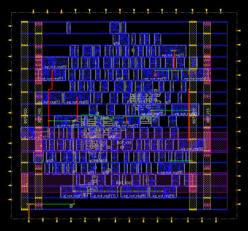
(a) Bottom-tier PDN grid
|
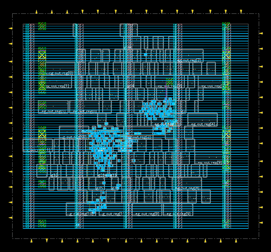
(b) Top-tier PDN grid
|
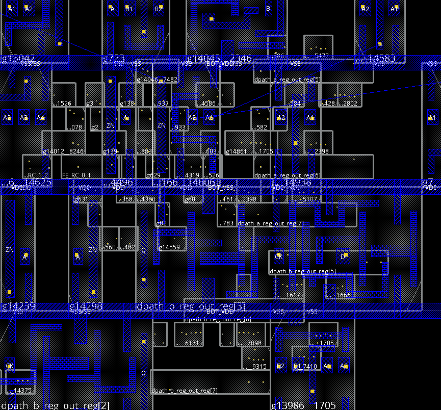
(c) Bottom-tier standard-cell placement
|
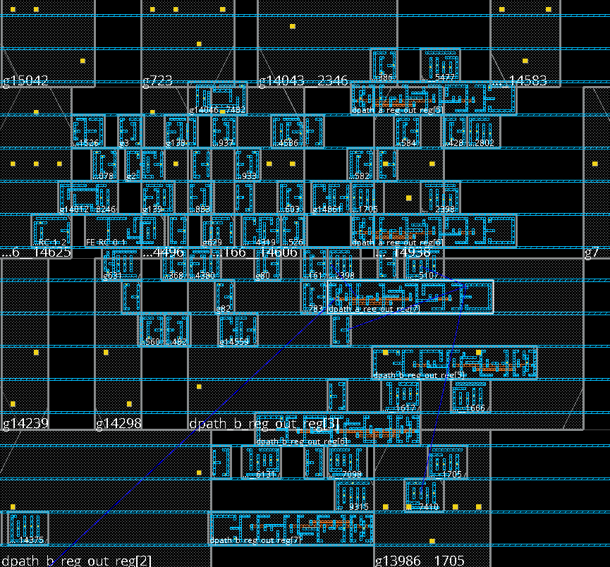
(d) Top-tier standard-cell placement
|
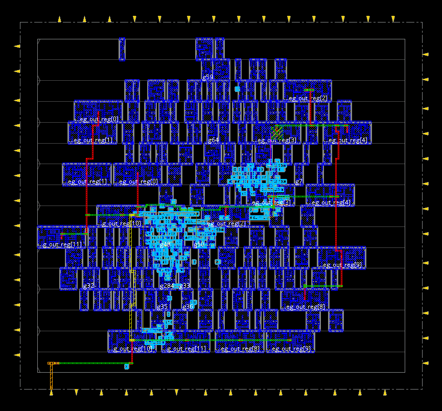
(e) Clock tree synthesis (CTS)
|
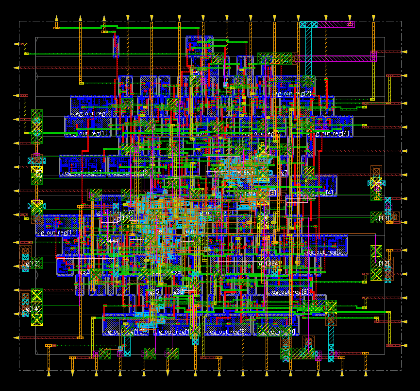
(f) Signal net routing
|
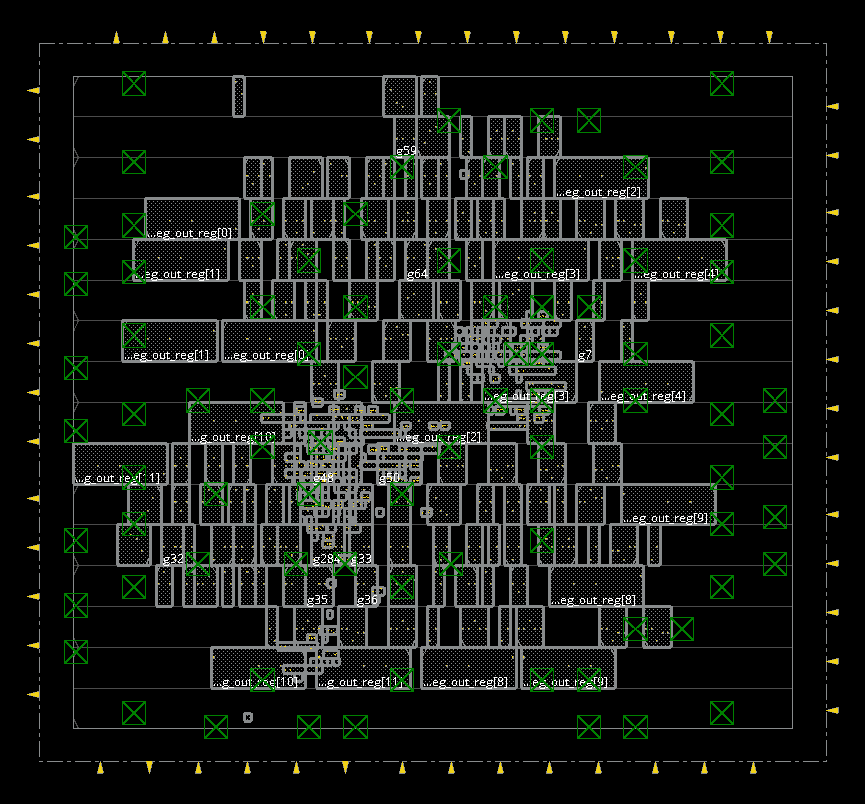
(g) HBTs assigned by the router
|
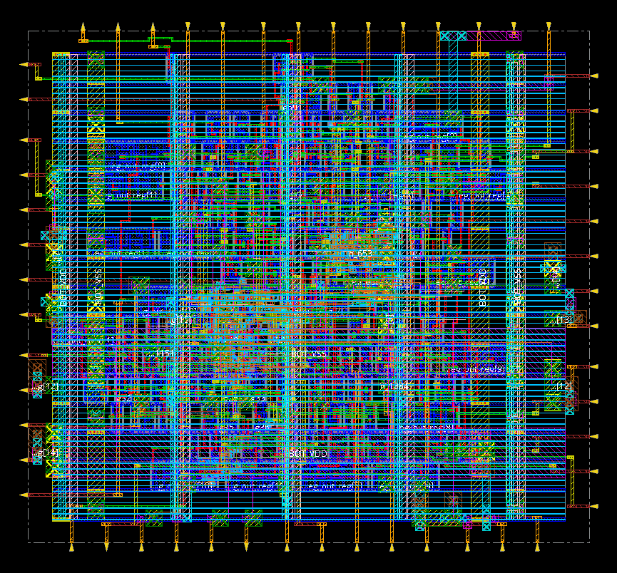
(h) Final 3D layout
|
## What Is Unique In This 3D Flow
This repository does not treat 3D IC implementation as a completely new backend flow. Instead, it reuses mature 2D engines and adds a small set of explicit 3D abstractions and stage controls that make the flow 3D-aware while keeping the toolchain practical and reproducible.
The key strategies are:
- **Unified 2D abstraction for F2F 3D**: hybrid bonding terminals (HBTs) are modeled as special vias in an extended metal stack, so existing 2D routers can realize cross-tier connections without a custom 3D router.
- **Tier-specific library views**: every physical cell has tier-local masters such as `*_bottom` and `*_upper`, and both OpenROAD and Cadence use COVER views to hide the inactive tier from local optimization while preserving logical connectivity.
- **Mixed-fanout split before detailed optimization**: the flow explicitly identifies nets whose real sinks span both tiers, inserts a tier-local split buffer to isolate one sink cluster, and converts one mixed-fanout net into two tier-pure fanout nets whenever possible. The buffer tier is selected with a lightweight cost model that penalizes high-util tiers and choices with higher estimated split-side HBT burden.
- **Tier-by-tier optimization instead of flat 3D optimization**: placement and legalization alternate between the upper and bottom tiers, with explicit tier policy, row/site rebuilding, and stage-specific active-tier control.
- **Split PDN and staged CTS**: PDN is built separately for bottom and upper tiers. CTS is structured as owner-tier tree construction followed by receive-tier clock repair/optimization, rather than a single flat 3D clock stage.
- **3D-specific observability**: the flow reports both structural `cross-tier` nets and functional `mixed_fanout` nets, because these are different quantities and they must be tracked separately during 3D optimization.
## [Enablements](#enablements)
PDK (Process Design Kit) preparation is a foundational component of a robust 3D physical design flow.
In this repository, we open-source three representative 3D stacking configurations derived from the NanGate45 and ASAP7 platforms in OpenROAD-flow-scripts:
- NanGate45-NanGate45
- ASAP7-ASAP7
- NanGate45-ASAP7
These configurations cover both **homogeneous** and **heterogeneous** technology stacks and are suitable for benchmarking, algorithm development, and flow validation.
### Example: Build your own 3D PDK
To illustrate the enablement methodology, we use the **ASAP7–ASAP7** configuration as a representative example. Starting from the standard 2D ASAP7 PDK, we derive a 3D-capable PDK by systematically extending the technology and library views.
- **Face-to-Face (F2F) Stack Modeling**: we model a **face-to-face (F2F)** stack by (i) replicating the original 2D metal stack on each tier, and (ii) introducing a **dedicated cut layer** to represent **hybrid bonding terminals (HBTs)** as vertical vias between tiers. Since the two dies in an F2F configuration are fabricated independently prior to bonding, we implement **symmetric yet electrically isolated power delivery networks (PDNs)** on the top and bottom tiers. This enables independent power supplies and voltage domains, which is essential for modeling heterogeneous 3D integration scenarios.
- **3D Standard-Cell Library Enablement**: we derive **tier-specific standard-cell libraries** from the base 2D library: (i) for each logical cell, we generate two physical LEF masters, where `*_bottom*` is used for the bottom tier and `*_upper*` for the top tier, and (ii) metal layers in each LEF are reassigned to the corresponding tier-local metal stack.
- **Die by Die Optimization**: we provide **COVER LEF** views for both tiers to enable die by die optimization. These views act as physical abstractions that: (i) exclude the inactive tier from overlap, density and congestion calculations, and (ii) preserve cross-tier connectivity and logical correctness.
This enablement strategy allows existing 2D physical design engines to operate on 3D designs with minimal modification, while retaining sufficient fidelity for meaningful tool and algorithm evaluation.
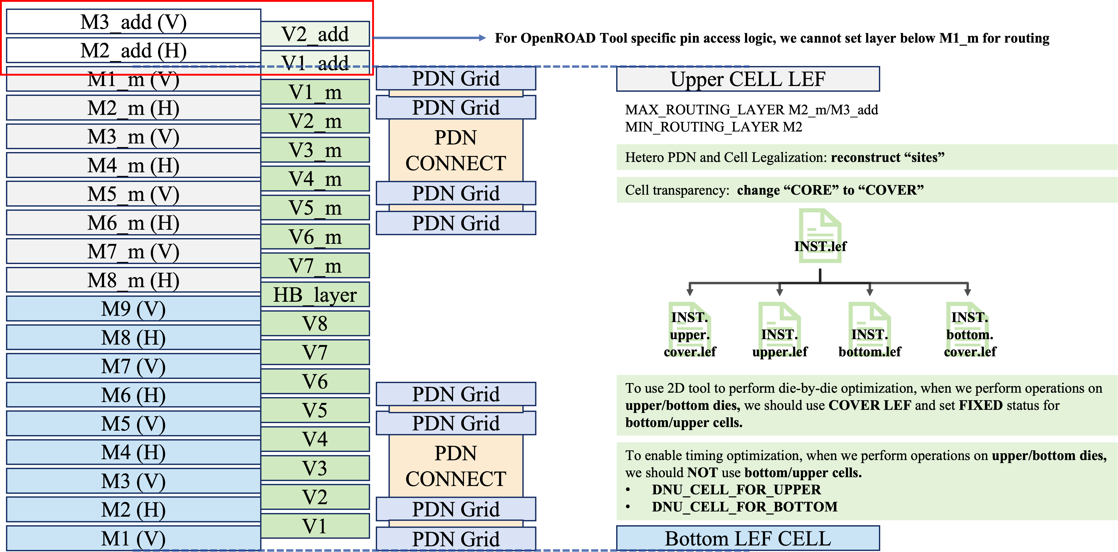
Figure: Metal stack, PDN strategy, and tier abstraction in the 3D ASAP7 PDK.
## [Implementaion Flows](#implementation-flow)
Our current 3D IC implementation flow is organized around a few explicit 3D stages rather than hidden tool-specific hacks:
- *Front-end 3D construction*: after 2D synthesis and partitioning, the flow builds tier-aware 3D floorplan, IO, split-net, macro-placement and PDN views.
- *Iterative tier-by-tier physical optimization*: upper and bottom tiers are optimized separately with inactive-tier COVER views and explicit tier policy.
- *Staged clocking and routing*: CTS is split into owner-tier tree construction and receive-tier clock repair/optimization, then routing uses the full merged 3D metal stack.
- *Stage-managed reproducibility*: every major stage writes canonical handoff files and metrics so the flow can be resumed, compared, and analyzed stage by stage.
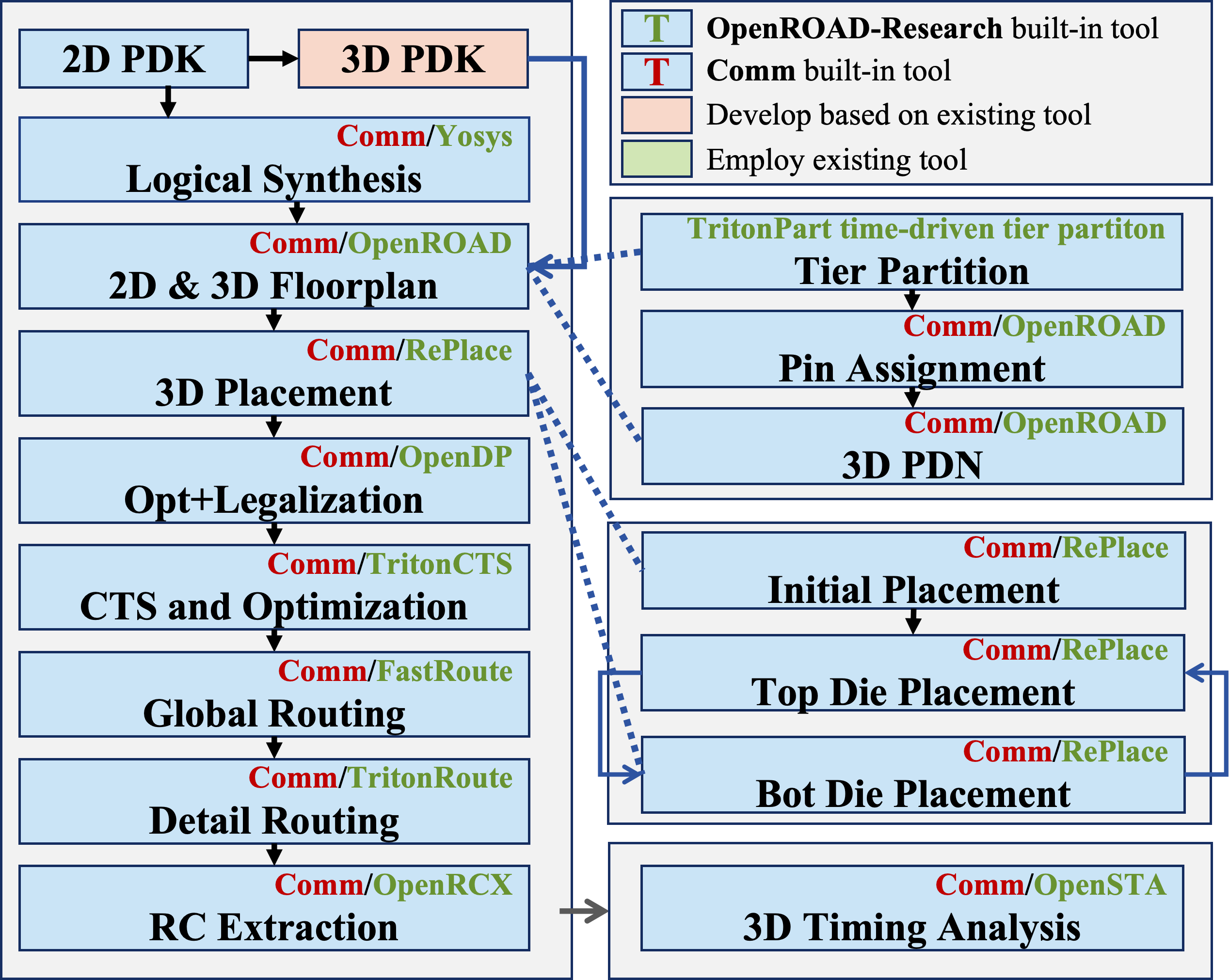
The following figure presents an overview of our homogeneous and heterogeneous Pin-3D physical design flow. The practical flow used in this repository has the following structure:
- **2D bootstrap**: RTL is synthesized, floorplanned and partitioned in 2D to generate the initial tier assignment.
- **3D floorplan and IO construction**: the partitioned design is converted into a tier-aware 3D view with tier-local libraries, tier-local PDN intent and HBT-capable routing resources.
- **Mixed-fanout split stage**: before the main physical optimization loop, the flow isolates one tier's sink cluster so later optimization works on cleaner tier-local fanout structure. The current split policy evaluates upper and bottom buffer placement using three lightweight terms: global tier utilization, an `estimated_extra_hbt` proxy, and the inserted buffer area normalized by the current core area. The HBT proxy is not the final routed HBT count.
- **Iterative 3D placement and legalization**: the flow alternates active optimization between upper and bottom tiers instead of optimizing both tiers blindly in one flat pass.
- **Staged 3D CTS**: `CTS_LAYER` selects the owner tier. The clock tree is first built from that owner-tier view and then refined from the receive side. The current `single_trunk_handoff` name describes this staged owner/receive flow; it does not enforce exactly one physical handoff point per clock domain.
- **3D route and final extraction**: routing uses the merged 3D stack, then timing, power, DRC and cross-tier reports are collected from final outputs.
### Key 3D Semantics
Two metrics are central to this flow and are intentionally treated as different objects:
- **Structural `cross-tier` net**: a net that still spans both tiers in the merged physical view. This is the physical HBT pressure metric.
- **Functional `mixed_fanout` net**: a net whose real sinks span both tiers. This is the optimization target of the split-net stage.
This distinction is important because a split operation may keep one controlled cross-tier bridge in the physical graph while still converting the original fanout into tier-pure branches for later optimization.
### [Stage-by-Stage](#Stage-by-Stage)
> The rows below summarize the current public stage graph used by the maintained OpenROAD and Cadence launchers.
| Stage | OpenROAD target | Cadence target | Notes |
| :---------------------- | :------------------------- | :------------------------- | :----------------------------------------------------------- |
| **Clean** | `clean_all` | `clean_all` | Remove `results/ reports/ logs/ objects/`. |
| **2D Bootstrap** | `ord-3d-flow-2dpart` | `cds-3d-flow-2dpart` | Runs synth, preplace and partition with `config2d.mk`. |
| **3D Prep (views)** | `ord-pre` | `cds-pre` | Import partition artifacts and build 3D logical views. |
| **3D Floorplan** | `ord-3d-floorplan` | `cds-3d-floorplan` | Build tier-aware floorplan from the partitioned design. |
| **3D IO** | `ord-3d-io` | `cds-3d-io` | Tier-aware IO/pin placement. |
| **Split Mixed Fanout** | `ord-3d-split-net` | `cds-3d-split-net` | Split mixed-fanout nets with cost-based buffer tier selection before main optimization. |
| **Macro Place — Upper** | `ord-place-macro-upper` | `cds-place-macro-upper` | Place upper-tier macros with inactive-tier abstraction. |
| **Macro Place — Bottom**| `ord-place-macro-bottom` | `cds-place-macro-bottom` | Place bottom-tier macros and merge handoff. |
| **3D PDN** | `ord-3d-pdn-only` | `cds-3d-pdn-only` | Runs bottom PDN then upper PDN explicitly. |
| **Place Init** | `ord-place-init` | `cds-place-init` | Initialize 3D placement state. |
| **Init — Upper** | `ord-place-init-upper` | `cds-place-init-upper` | Optional upper-owner init refinement. |
| **Init — Bottom** | `ord-place-init-bottom` | `cds-place-init-bottom` | Optional bottom-owner init refinement. |
| **Place — Upper Tier** | `ord-place-upper` | `cds-place-upper` | Upper-owner timing/congestion refinement. |
| **Place — Bottom Tier** | `ord-place-bottom` | `cds-place-bottom` | Bottom-owner timing/congestion refinement. |
| **GP to LG Handoff** | `ord-gp2lg` | `cds-gp2lg` | Convert iterative global-placement handoff to legalize view. |
| **Legalize — Upper** | `ord-legalize-upper` | `cds-legalize-upper` | Upper-owner legalization and preCTS cleanup. |
| **Legalize — Bottom** | `ord-legalize-bottom` | `cds-legalize-bottom` | Bottom-owner legalization and merged place handoff. |
| **CTS Owner Stage** | `ord-cts` | `cds-cts` | Owner-tree CTS stage. |
| **CTS Receive Stage** | `ord-cts-post` | `cds-cts` | Receive-side clock optimization and cleanup. |
| **Route (3D)** | `ord-route` | `cds-route` | Full 3D routing on the merged stack with HBT generation. |
| **Final / Reports** | `ord-final` | `cds-restore/final` | Final reports, summaries, and restored final database. |
| **Thermal / Hotspot** | `ord-hotspot` | | Reuses OpenROAD HotSpot harness. |
For quick stage-level debugging or restart, a single make target can be launched directly with:
```bash
bash test/common/run_stage.sh
```
Example:
```bash
bash test/common/run_stage.sh asap7_3D debug_openroad openroad ibex ord-cts
bash test/common/run_stage.sh asap7_nangate45_3D debug_cadence cadence gcd cds-pre
```
### [Outputs](#Outputs)
After runs, you will typically see:
```
results/ # DEF/ODB/LEF/SPEF/GDS, etc.
reports/ # timing/power/HPWL/congestion/clock, etc.
logs/ # tool logs (OpenROAD/Cadence), final summary, plots
objects/ # intermediate DBs and caches
```
## Contacts
We welcome feedback, suggestions and contributions that help improve this repository, including enhanced materials, bug fixes and extensions. Please feel free to reach out via email, GitHub Issues or Pull Requests. Contact information for the maintainers is listed below.
* **Zhiang Wang** — [zhiangwang@fudan.edu.cn](mailto:zhiangwang@fudan.edu.cn)
* **Zhiyu Zheng** — [zyzheng24@m.fudan.edu.cn](mailto:zyzheng24@m.fudan.edu.cn)
Before using this repository, please carefully review the header notices in all TCL scripts that invoke commercial EDA tools.
We gratefully acknowledge Cadence and Synopsys for permitting, in an academic research context, the inclusion of limited excerpts of their copyrighted intellectual property for researchers’ use.
If your research, products or publications benefit from this repository, we kindly ask that you cite the relevant papers listed below.
## References
[1] L. Jiang, A. B. Kahng, Z. Wang*, Z. Zheng, "Invited: Toward Sustainable and Transparent Benchmarking for Academic Physical Design Research", Proc. ISPD, 2026.