# WiFiDeviceDetector
### **A simple Raspberry Pi based device detector that uses a Ralink RT5370-based WiPi dongle to detect if there are any wifi enabled devices nearby.**
 # How does it work?
The WiPi dongle contains a Wi-Fi chip manufactured by Ralink. That chip has the ability to go into something called Monitor Mode. In this mode, the chip can pick up wifi signals and decode them. It turns out that, whenever a device wants to look for wifi networks, it has two options:
1. Wait for the router(s) to send a periodic signal containing their information (very slow).
2. Send a request for all routers to send their info on their respective channel.
Usually, a device chooses the second option. Now, in Monitor Mode, the Ralink chip can pick up those requests and, using their signal strength, determine how far the device is. The signal strength is then used to determine the severity:
* < -70 dBm - extremely far away (severity score 0)
* -70 to -50 dBm - far away to nearby (severity score 1)
* -50 to ∞ dBm - close to extremely close (severity score 2)
Each severity score has a color on the traffic light module:
* 0 - Green
* 1 - Yellow
* 2 - Red
The severity also decays over time. The time in which severity decays can be set by adjusting the severity_timeout variable in main.py.
### Notes:
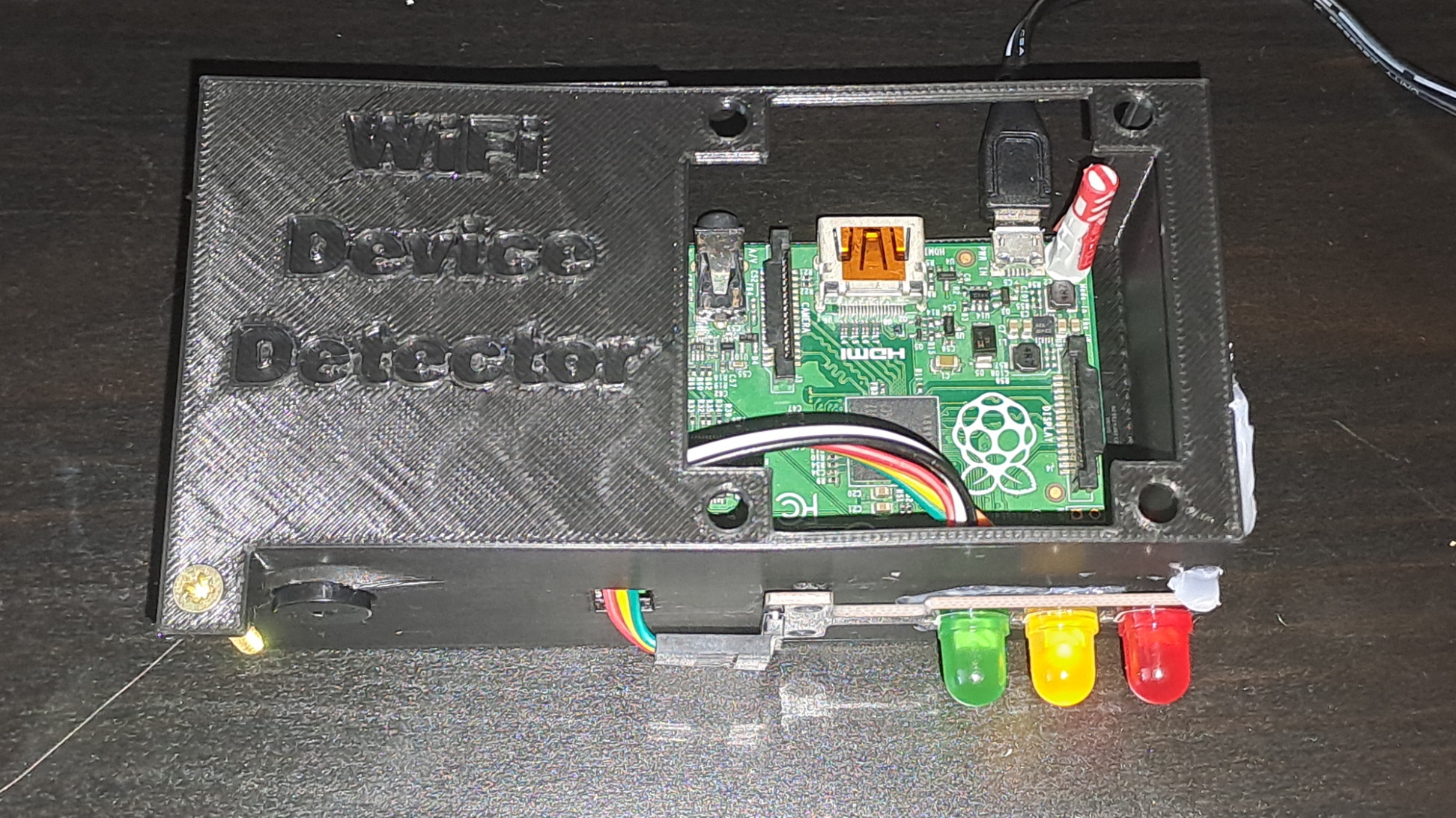
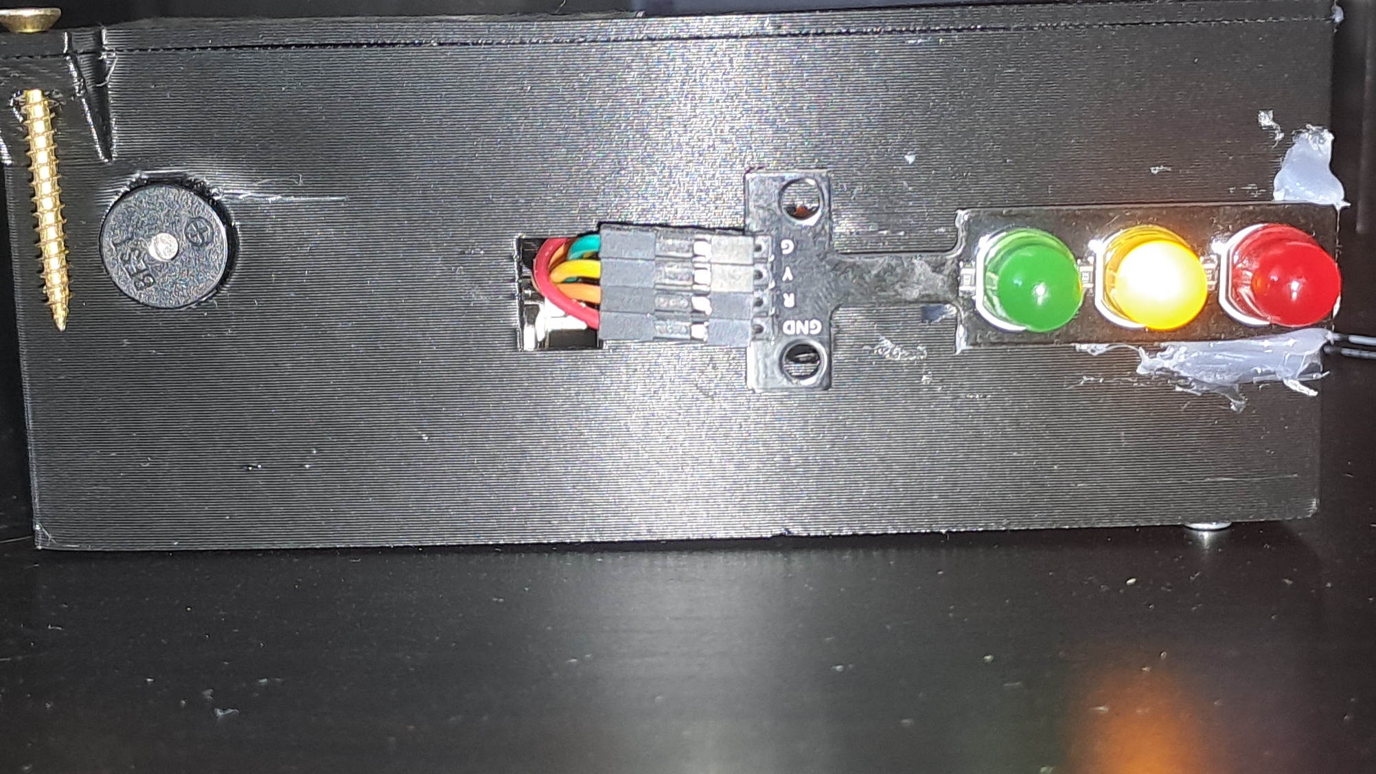
In my build, I have resorted to hot-gluing because the dimensions weren't quite right for the traffic light module (in the 3D files it's fine). There is supposed to be a 60mm fan on the top, but mine wouldn't power on with the 5V from the RPi rev 1.2.
# How to replicate it?
It is quite simple to replicate what I've done. First, let's start with the physical part of the project:
1. Get yourself a Raspberry Pi 1, 2, or 3 (it might work with a 4 or 5, but I have not tested it) model B+, a WiFi adapter with a chip that has the ability to be put into Monitor Mode, an active buzzer, an LED traffic light module or three LEDs , a 60mm 5v fan a 12v one might work and a handful of wires (female-to-male and female-to-female).
2. Connect the traffic light module using some female-to-female wires to the pins:
* GND - GND
* RED - GP14
* YELLOW - GP15
* GREEN - GP18
3. Connect the buzzer:
* GND - GND
* VCC - GP32
4. Plug in the WiFi dongle and the power cable.
**If you have 3D printed the case:**
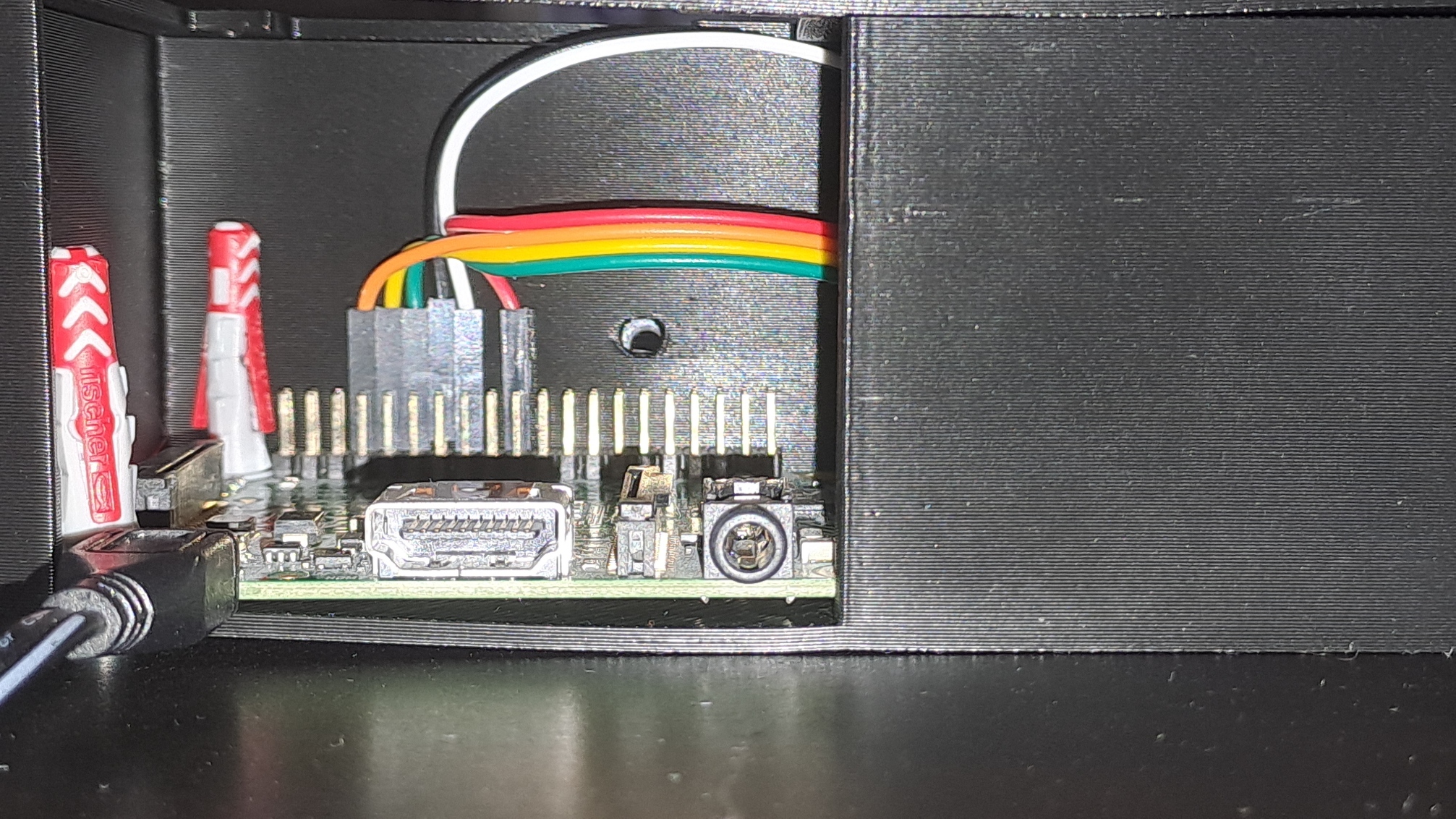
5. Disconnect the wires from the LED traffic light module's pins for a moment.
6. Route the wires through the rectangular hole.
7. Reconnect the wires to the module's pins.
8. Screw in the traffic light module.
9. Push part of the buzzer through the hole next to the traffic light module.
10. Screw in the fan.
11. Using your favorite method, connect the fan:
* VCC - DC 5V
* GND - GND
*I used Wago connectors with some male-to-male cables.
11. Screw in a screw in the screw hole on the top.
**Physical part done!**
12. Connect to the RPi using ssh or keyboard + monitor.
13. Download the main.py file.
14. Install scapy (you can use `sudo apt install python3-scapy`).
**All done!**
To run the script, just type in `sudo python3 main.py` (preferably over keyboard).
### Optional stuff:
You can create a rc.local file in /etc so that the script runs at startup! The syntax is just like a sh file. All you need to do is `sudo chmod 755 /etc/rc.local`.
# How does it work?
The WiPi dongle contains a Wi-Fi chip manufactured by Ralink. That chip has the ability to go into something called Monitor Mode. In this mode, the chip can pick up wifi signals and decode them. It turns out that, whenever a device wants to look for wifi networks, it has two options:
1. Wait for the router(s) to send a periodic signal containing their information (very slow).
2. Send a request for all routers to send their info on their respective channel.
Usually, a device chooses the second option. Now, in Monitor Mode, the Ralink chip can pick up those requests and, using their signal strength, determine how far the device is. The signal strength is then used to determine the severity:
* < -70 dBm - extremely far away (severity score 0)
* -70 to -50 dBm - far away to nearby (severity score 1)
* -50 to ∞ dBm - close to extremely close (severity score 2)
Each severity score has a color on the traffic light module:
* 0 - Green
* 1 - Yellow
* 2 - Red
The severity also decays over time. The time in which severity decays can be set by adjusting the severity_timeout variable in main.py.
### Notes:
In my build, I have resorted to hot-gluing because the dimensions weren't quite right for the traffic light module (in the 3D files it's fine). There is supposed to be a 60mm fan on the top, but mine wouldn't power on with the 5V from the RPi rev 1.2.
# How to replicate it?
It is quite simple to replicate what I've done. First, let's start with the physical part of the project:
1. Get yourself a Raspberry Pi 1, 2, or 3 (it might work with a 4 or 5, but I have not tested it) model B+, a WiFi adapter with a chip that has the ability to be put into Monitor Mode, an active buzzer, an LED traffic light module or three LEDs , a 60mm 5v fan a 12v one might work and a handful of wires (female-to-male and female-to-female).
2. Connect the traffic light module using some female-to-female wires to the pins:
* GND - GND
* RED - GP14
* YELLOW - GP15
* GREEN - GP18
3. Connect the buzzer:
* GND - GND
* VCC - GP32
4. Plug in the WiFi dongle and the power cable.
**If you have 3D printed the case:**
5. Disconnect the wires from the LED traffic light module's pins for a moment.
6. Route the wires through the rectangular hole.
7. Reconnect the wires to the module's pins.
8. Screw in the traffic light module.
9. Push part of the buzzer through the hole next to the traffic light module.
10. Screw in the fan.
11. Using your favorite method, connect the fan:
* VCC - DC 5V
* GND - GND
*I used Wago connectors with some male-to-male cables.
11. Screw in a screw in the screw hole on the top.
**Physical part done!**
12. Connect to the RPi using ssh or keyboard + monitor.
13. Download the main.py file.
14. Install scapy (you can use `sudo apt install python3-scapy`).
**All done!**
To run the script, just type in `sudo python3 main.py` (preferably over keyboard).
### Optional stuff:
You can create a rc.local file in /etc so that the script runs at startup! The syntax is just like a sh file. All you need to do is `sudo chmod 755 /etc/rc.local`.