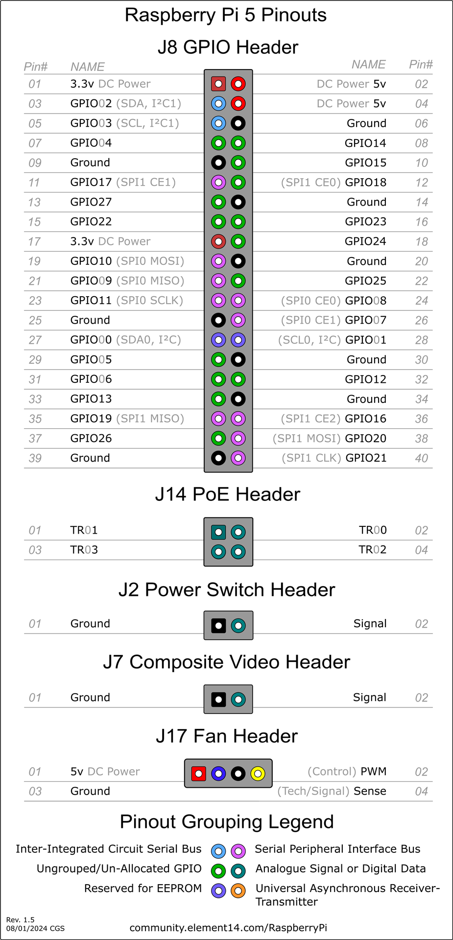
# Raspberry Pi 5 Pinout
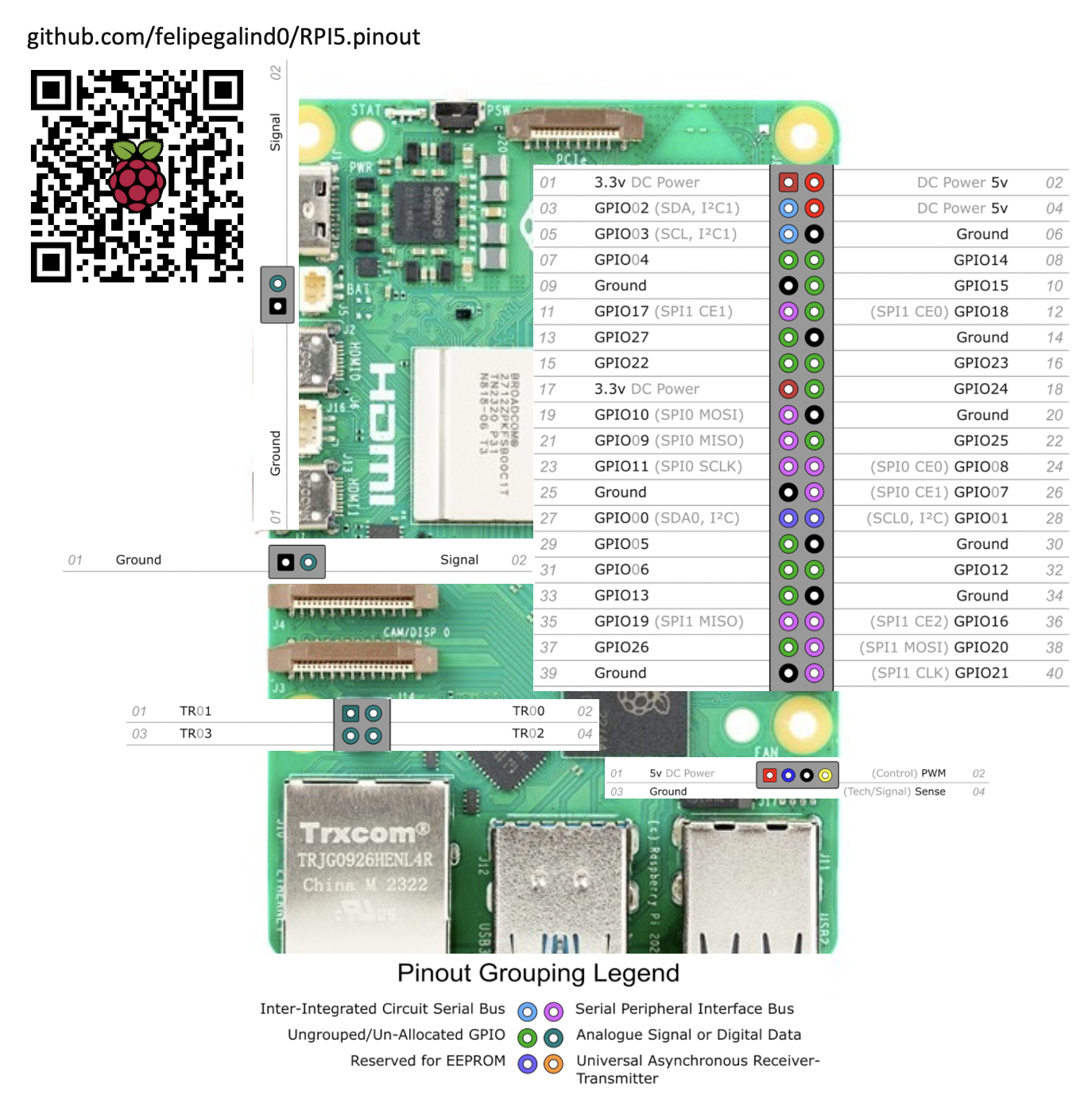
The RP1 on the RPI5 has 28 multi-functional General-Purpose Input/Output pins available on the Raspberry Pi 40-pin
GPIO connector.
GPIO pins can withstand upto 5V when RP1 is powered, and 3.63V when RP1 is unpowered.
The pins are in a single electrical bank (VDDIO0). The GPIO bank (IO_BANK0) can be powered from 1.8V or 3.3V, but
interface timings have been specified at 3.3V.
Each pin can be controlled directly by software, or by a number of other functional blocks.
The bank supports the following functions:
```
• 5 × UART
• 6 × SPI
• 4 × I2C
• 2 × I2S - 1× Clock Producer instance, 1× Clock Consumer instance.
• RIO - Registered IO interface
• 24-bit DPI output
• 4-channel PWM output
• AUDIO_OUT - Stereo PWM audio output
• GPCLK - General-purpose clock input and output
• eMMC/SDIO bus with a 4-bit interface
• Interrupt generation from pin level or edge transitions
```
| GPIO Number | Function | | | | | | | | |
|----------|--------------|-----------|--------------|---------------|-------------|--------------|--------------|-------------|-------------|
| GPIO# | F1 | F2 | F3 | F4 | F5 | F6 | F7 | F8 | F9 |
| GPIO0 | SPI0_SIO[3] | DPI_PCLK | UART1_TX | I2C0_SDA | SYS_RIO[0] | PROC_RIO[0] | PIO[0] | SPI2_CSn[0] | |
| GPIO1 | SPI0_SIO[2] | DPI_DE | UART1_RX | I2C0_SCL | SYS_RIO[1] | PROC_RIO[1] | PIO[1] | SPI2_SIO[1] | |
| GPIO2 | SPI0_CSn[3] | DPI_VSYNC | UART1_CTS | I2C1_SDA | UART0_IR_RX | SYS_RIO[2] | PROC_RIO[2] | PIO[2] | SPI2_SIO[0] |
| GPIO3 | SPI0_CSn[2] | DPI_HSYNC | UART1_RTS | I2C1_SCL | UART0_IR_TX | SYS_RIO[3] | PROC_RIO[3] | PIO[3] | SPI2_SCLK |
| GPIO4 | GPCLK[0] | DPI_D[0] | UART2_TX | I2C2_SDA | UART0_RI | SYS_RIO[4] | PROC_RIO[4] | PIO[4] | SPI3_CSn[0] |
| GPIO5 | GPCLK[1] | DPI_D[1] | UART2_RX | I2C2_SCL | UART0_DTR | SYS_RIO[5] | PROC_RIO[5] | PIO[5] | SPI3_SIO[1] |
| GPIO6 | GPCLK[2] | DPI_D[2] | UART2_CTS | I2C3_SDA | UART0_DCD | SYS_RIO[6] | PROC_RIO[6] | PIO[6] | SPI3_SIO[0] |
| GPIO7 | SPI0_CSn[1] | DPI_D[3] | UART2_RTS | I2C3_SCL | UART0_DSR | SYS_RIO[7] | PROC_RIO[7] | PIO[7] | SPI3_SCLK |
| GPIO8 | SPI0_CSn[0] | DPI_D[4] | UART3_TX | I2C0_SDA | SYS_RIO[8] | PROC_RIO[8] | PIO[8] | SPI4_CSn[0] | |
| GPIO9 | SPI0_SIO[1] | DPI_D[5] | UART3_RX | I2C0_SCL | SYS_RIO[9] | PROC_RIO[9] | PIO[9] | SPI4_SIO[0] | |
| GPIO10 | SPI0_SIO[0] | DPI_D[6] | UART3_CTS | I2C1_SDA | SYS_RIO[10] | PROC_RIO[10] | PIO[10] | SPI4_SIO[1] | |
| GPIO11 | SPI0_SCLK | DPI_D[7] | UART3_RTS | I2C1_SCL | SYS_RIO[11] | PROC_RIO[11] | PIO[11] | SPI4_SCLK | |
| GPIO12 | PWM0[0] | DPI_D[8] | UART4_TX | I2C2_SDA | AUDIO_OUT_L | SYS_RIO[12] | PROC_RIO[12] | PIO[12] | SPI5_CSn[0] |
| GPIO13 | PWM0[1] | DPI_D[9] | UART4_RX | I2C2_SCL | AUDIO_OUT_R | SYS_RIO[13] | PROC_RIO[13] | PIO[13] | SPI5_SIO[1] |
| GPIO14 | PWM0[2] | DPI_D[10] | UART4_CTS | I2C3_SDA | UART0_TX | SYS_RIO[14] | PROC_RIO[14] | PIO[14] | SPI5_SIO[0] |
| GPIO15 | PWM0[3] | DPI_D[11] | UART4_RTS | I2C3_SCL | UART0_RX | SYS_RIO[15] | PROC_RIO[15] | PIO[15] | SPI5_SCLK |
| GPIO16 | SPI1_CSn[2] | DPI_D[12] | MIPI0_DSI_TE | UART0_CTS | SYS_RIO[16] | PROC_RIO[16] | PIO[16] | | |
| GPIO17 | SPI1_CSn[1] | DPI_D[13] | MIPI1_DSI_TE | UART0_RTS | SYS_RIO[17] | PROC_RIO[17] | PIO[17] | | |
| GPIO18 | SPI1_CSn[0] | DPI_D[14] | I2S0_SCLK | PWM0[2] | I2S1_SCLK | SYS_RIO[18] | PROC_RIO[18] | PIO[18] | GPCLK[1] |
| GPIO19 | SPI1_SIO[1] | DPI_D[15] | I2S0_WS | PWM0[3] | I2S1_WS | SYS_RIO[19] | PROC_RIO[19] | PIO[19] | |
| GPIO20 | SPI1_SIO[0] | DPI_D[16] | I2S0_SDI[0] | GPCLK[0] | I2S1_SDI[0] | SYS_RIO[20] | PROC_RIO[20] | PIO[20] | |
| GPIO21 | SPI1_SCLK | DPI_D[17] | I2S0_SDO[0] | GPCLK[1] | I2S1_SDO[0] | SYS_RIO[21] | PROC_RIO[21] | PIO[21] | |
| GPIO22 | SDIO0_CLK | DPI_D[18] | I2S0_SDI[1] | I2C3_SDA | I2S1_SDI[1] | SYS_RIO[22] | PROC_RIO[22] | PIO[22] | |
| GPIO23 | SDIO0_CMD | DPI_D[19] | I2S0_SDO[1] | I2C3_SCL | I2S1_SDO[1] | SYS_RIO[23] | PROC_RIO[23] | PIO[23] | |
| GPIO24 | SDIO0_DAT[0] | DPI_D[20] | I2S0_SDI[2] | I2S1_SDI[2] | SYS_RIO[24] | PROC_RIO[24] | PIO[24] | SPI2_CSn[1] | |
| GPIO25 | SDIO0_DAT[1] | DPI_D[21] | I2S0_SDO[2] | AUDIO_IN_CLK | I2S1_SDO[2] | SYS_RIO[25] | PROC_RIO[25] | PIO[25] | SPI3_CSn[1] |
| GPIO26 | SDIO0_DAT[2] | DPI_D[22] | I2S0_SDI[3] | AUDIO_IN_DAT0 | I2S1_SDI[3] | SYS_RIO[26] | PROC_RIO[26] | PIO[26] | SPI5_CSn[1] |
| GPIO27 | SDIO0_DAT[3] | DPI_D[23] | I2S0_SDO[3] | AUDIO_IN_DAT1 | I2S1_SDO[3] | SYS_RIO[27] | PROC_RIO[27] | PIO[27] | SPI1_CSn[1] |
Each GPIO can have one function selected at a time. Likewise, each peripheral input (e.g. I2C3_SCL) should only be selected on one GPIO at a time. If the same peripheral input is connected to multiple GPIOs, the peripheral sees the logical OR of these GPIO inputs. Function selections without a named function in this list are reserved.
To enable a specific UART, add the corresponding overlay to /boot/config.txt. For example, to enable UART 1 on GPIOs 0 and 1, add the following line to /boot/config.txt:
```
dtoverlay=uart1-pi5
```
# PCIe & NVMe
See ['github.com/m1geo/Pi5_PCIe'](https://github.com/m1geo/Pi5_PCIe)
& [datasheets.raspberrypi.com/pcie/pcie-connector-standard.pdf](https://datasheets.raspberrypi.com/pcie/pcie-connector-standard.pdf)
# UARTs
## ⚠️ Warning: UART does *NOT* work on the RPI5 from the factory.
A firmware update is required fix a [known issue](https://forums.raspberrypi.com/viewtopic.php?t=361397#p2171244) that prevents the dtoverlays for UARTs from working.
### Fix:
Install [rpi-update](https://github.com/Hexxeh/rpi-update) on Ubuntu 23.10 with the following commands:
```
sudo curl -L --output /usr/bin/rpi-update https://raw.githubusercontent.com/Hexxeh/rpi-update/master/rpi-update && sudo chmod +x /usr/bin/rpi-update
```
Then update the firmware on your RPI5 with:
```
sudo rpi-update
```
### [dtoverlays](https://raw.githubusercontent.com/raspberrypi/firmware/master/boot/overlays/README) for I2C:
```
dtoverlay=i2c0-pi5,pins_8_9
dtoverlay=i2c1-pi5,pins_10_11
dtoverlay=i2c2-pi5,pins_12_13
#dtoverlay=i2c3-pi5,pins_22_23 #default 14-15: ! same as UART0
```
```
i2c An alias for i2c_arm
i2c_arm Set to "on" to enable the ARM's i2c interface
(default "off")
i2c_arm_baudrate Set the baudrate of the ARM's i2c interface
(default "100000")
i2c_baudrate An alias for i2c_arm_baudrate
i2c_csi_dsi Set to "on" to enable the i2c_csi_dsi interface
i2c_csi_dsi0 Set to "on" to enable the i2c_csi_dsi0 interface
i2c_csi_dsi1 Set to "on" to enable the i2c_csi_dsi1 interface
i2c_vc Set to "on" to enable the i2c interface
usually reserved for the VideoCore processor
(default "off")
i2c_vc_baudrate Set the baudrate of the VideoCore i2c interface
(default "100000")
```
```
Name: i2c0
Info: Change i2c0 pin usage. Not all pin combinations are usable on all
platforms - platforms other then Compute Modules can only use this
to disable transaction combining.
Do NOT use in conjunction with dtparam=i2c_vc=on. From the 5.4 kernel
onwards the base DT includes the use of i2c_mux_pinctrl to expose two
muxings of BSC0 - GPIOs 0&1, and whichever combination is used for the
camera and display connectors. This overlay disables that mux and
configures /dev/i2c0 to point at whichever set of pins is requested.
dtparam=i2c_vc=on will try and enable the mux, so combining the two
will cause conflicts.
Load: dtoverlay=i2c0,=
Params: pins_0_1 Use pins 0 and 1 (default)
pins_28_29 Use pins 28 and 29
pins_44_45 Use pins 44 and 45
pins_46_47 Use pins 46 and 47
combine Allow transactions to be combined (default
"yes")
Name: i2c0-bcm2708
Info: Deprecated, legacy version of i2c0.
Load:
Name: i2c0-pi5
Info: Enable i2c0 (Pi 5 only)
Load: dtoverlay=i2c0-pi5,=
Params: pins_0_1 Use GPIOs 0 and 1 (default)
pins_8_9 Use GPIOs 8 and 9
baudrate Set the baudrate for the interface (default
"100000")
Name: i2c1
Info: Change i2c1 pin usage. Not all pin combinations are usable on all
platforms - platforms other then Compute Modules can only use this
to disable transaction combining.
Load: dtoverlay=i2c1,=
Params: pins_2_3 Use pins 2 and 3 (default)
pins_44_45 Use pins 44 and 45
combine Allow transactions to be combined (default
"yes")
Name: i2c1-bcm2708
Info: Deprecated, legacy version of i2c1.
Load:
Name: i2c1-pi5
Info: Enable i2c1 (Pi 5 only)
Load: dtoverlay=i2c1-pi5,=
Params: pins_2_3 Use GPIOs 2 and 3 (default)
pins_10_11 Use GPIOs 10 and 11
baudrate Set the baudrate for the interface (default
"100000")
Name: i2c2-pi5
Info: Enable i2c2 (Pi 5 only)
Load: dtoverlay=i2c2-pi5,=
Params: pins_4_5 Use GPIOs 4 and 5 (default)
pins_12_13 Use GPIOs 12 and 13
baudrate Set the baudrate for the interface (default
"100000")
Name: i2c3
Info: Enable the i2c3 bus. BCM2711 only.
Load: dtoverlay=i2c3,
Params: pins_2_3 Use GPIOs 2 and 3
pins_4_5 Use GPIOs 4 and 5 (default)
baudrate Set the baudrate for the interface (default
"100000")
Name: i2c3-pi5
Info: Enable i2c3 (Pi 5 only)
Load: dtoverlay=i2c3-pi5,=
Params: pins_6_7 Use GPIOs 6 and 7 (default)
pins_14_15 Use GPIOs 14 and 15
pins_22_23 Use GPIOs 22 and 23
baudrate Set the baudrate for the interface (default
"100000")
Name: i2c4
Info: Enable the i2c4 bus. BCM2711 only.
Load: dtoverlay=i2c4,
Params: pins_6_7 Use GPIOs 6 and 7
pins_8_9 Use GPIOs 8 and 9 (default)
baudrate Set the baudrate for the interface (default
"100000")
Name: i2c5
Info: Enable the i2c5 bus. BCM2711 only.
Load: dtoverlay=i2c5,
Params: pins_10_11 Use GPIOs 10 and 11
pins_12_13 Use GPIOs 12 and 13 (default)
baudrate Set the baudrate for the interface (default
"100000")
Name: i2c6
Info: Enable the i2c6 bus. BCM2711 only.
Load: dtoverlay=i2c6,
Params: pins_0_1 Use GPIOs 0 and 1
pins_22_23 Use GPIOs 22 and 23 (default)
baudrate Set the baudrate for the interface (default
"100000")
```
### [dtoverlays](https://raw.githubusercontent.com/raspberrypi/firmware/master/boot/overlays/README) for UARTs:
```
Name: uart0
Info: Change the pin usage of uart0
Load: dtoverlay=uart0,=
Params: txd0_pin GPIO pin for TXD0 (14, 32 or 36 - default 14)
rxd0_pin GPIO pin for RXD0 (15, 33 or 37 - default 15)
pin_func Alternative pin function - 4(Alt0) for 14&15,
7(Alt3) for 32&33, 6(Alt2) for 36&37
Name: uart0-pi5
Info: Enable uart 0 on GPIOs 14-15. Pi 5 only.
Load: dtoverlay=uart0-pi5,
Params: ctsrts Enable CTS/RTS on GPIOs 16-17 (default off)
Name: uart1
Info: Change the pin usage of uart1
Load: dtoverlay=uart1,=
Params: txd1_pin GPIO pin for TXD1 (14, 32 or 40 - default 14)
rxd1_pin GPIO pin for RXD1 (15, 33 or 41 - default 15)
Name: uart1-pi5
Info: Enable uart 1 on GPIOs 0-1. Pi 5 only.
Load: dtoverlay=uart1-pi5,
Params: ctsrts Enable CTS/RTS on GPIOs 2-3 (default off)
Name: uart2
Info: Enable uart 2 on GPIOs 0-3. BCM2711 only.
Load: dtoverlay=uart2,
Params: ctsrts Enable CTS/RTS on GPIOs 2-3 (default off)
Name: uart2-pi5
Info: Enable uart 2 on GPIOs 4-5. Pi 5 only.
Load: dtoverlay=uart2-pi5,
Params: ctsrts Enable CTS/RTS on GPIOs 6-7 (default off)
Name: uart3
Info: Enable uart 3 on GPIOs 4-7. BCM2711 only.
Load: dtoverlay=uart3,
Params: ctsrts Enable CTS/RTS on GPIOs 6-7 (default off)
Name: uart3-pi5
Info: Enable uart 3 on GPIOs 8-9. Pi 5 only.
Load: dtoverlay=uart3-pi5,
Params: ctsrts Enable CTS/RTS on GPIOs 10-11 (default off)
Name: uart4
Info: Enable uart 4 on GPIOs 8-11. BCM2711 only.
Load: dtoverlay=uart4,
Params: ctsrts Enable CTS/RTS on GPIOs 10-11 (default off)
Name: uart4-pi5
Info: Enable uart 4 on GPIOs 12-13. Pi 5 only.
Load: dtoverlay=uart4-pi5,
Params: ctsrts Enable CTS/RTS on GPIOs 14-15 (default off)
Name: uart5
Info: Enable uart 5 on GPIOs 12-15. BCM2711 only.
Load: dtoverlay=uart5,
Params: ctsrts Enable CTS/RTS on GPIOs 14-15 (default off)
```
Default device tree overlay pinout:
Sources:
[RPI5.jgp](https://www.pishop.us/product/raspberry-pi-5-4gb/)
[Raspberry Pi 5 Pinouts](https://community.element14.com/products/raspberry-pi/m/files/148385)
RP1 is a peripheral controller, designed by Raspberry Pi for use on Raspberry Pi 5. It connects to an application processor (AP),the 16nm Broadcom BCM2712, via a PCIe 2.0 x4 bus, and aggregates many digital controllers and analog PHYs for Raspberry Pi 5’s external interfaces.
---
## Python GPIO Libraries on Raspberry Pi 5
The widely-used `RPi.GPIO` library is **not compatible** with the Raspberry Pi 5 and will not work.
This is due to the new RP1 I/O controller chip, which changes how GPIO pins are accessed at a low level. Attempting to use `RPi.GPIO` will result in an error.
The officially recommended Python libraries for controlling GPIO on the Raspberry Pi 5 are **GPIO Zero** (for beginners and most use cases) and **gpiod** (for intermediate/advanced use).
### 1. GPIO Zero (Recommended for Most Users)
**GPIO Zero** is a high-level, beginner-friendly library that represents components as objects (like `LED`, `Button`, `Motor`). It is pre-installed on Raspberry Pi OS and has been updated to work seamlessly with the Pi 5 by using a compatible backend (`lgpio`) automatically.
**Example: Blink an LED on GPIO 17**
```python
from gpiozero import LED
from time import sleep
# Use GPIO pin 17 (physical pin 11)
led = LED(17)
print("Press Ctrl+C to exit")
try:
while True:
led.on() # Turn the LED on
sleep(1)
led.off() # Turn the LED off
sleep(1)
except KeyboardInterrupt:
print("\nExiting...")
led.close()
```
### 2. gpiod (Lower-Level Control)
For users who need more direct, lower-level control similar to what `RPi.GPIO` provided, the modern library to use is **gpiod**. It is the standard, kernel-supported way to interact with GPIO pins on Linux.
**Installation:**
```bash
sudo apt update
sudo apt install python3-gpiod
```
**Example: Blink an LED on GPIO 17**
Note that the code is more verbose, as it provides more direct control. On the Raspberry Pi 5, the GPIO pins are on `gpiochip4`.
```python
import gpiod
import time
# On Raspberry Pi 5, the GPIO pins are on chip 4
CHIP = 'gpiochip4'
LED_LINE = 17 # Use GPIO pin 17
# Request the chip and the specific GPIO line
chip = gpiod.Chip(CHIP)
led_line = chip.get_line(LED_LINE)
# Configure the line as an output
led_line.request(consumer="my-led", type=gpiod.LINE_REQ_DIR_OUT)
print("Press Ctrl+C to exit")
try:
while True:
led_line.set_value(1) # Turn the LED on
time.sleep(1)
led_line.set_value(0) # Turn the LED off
time.sleep(1)
except KeyboardInterrupt:
print("\nExiting...")
finally:
# Release the line so other programs can use it
led_line.release()
```
# Amazon Links:
8gb board:
https://amzn.to/4o7dBUU
16gb board:
https://amzn.to/4qbC9Oh
Official heatsink:
https://amzn.to/3KRpu2R
Upgraded geekworm heatsink:
https://amzn.to/499peGl