# Pati
A voice companion robot for children, built on an ESP32-S3.
Pati runs no local model. Audio streams from the device to the Gemini
Live API over a raw WebSocket and returns to the speaker the same way.
No companion app, no intermediate server, no pairing step. Settings are
managed from a web panel served by the robot itself.
The hardware is one part — an M5Stack StickS3 — with the microphone,
speaker, display and battery already inside it. Nothing is soldered.
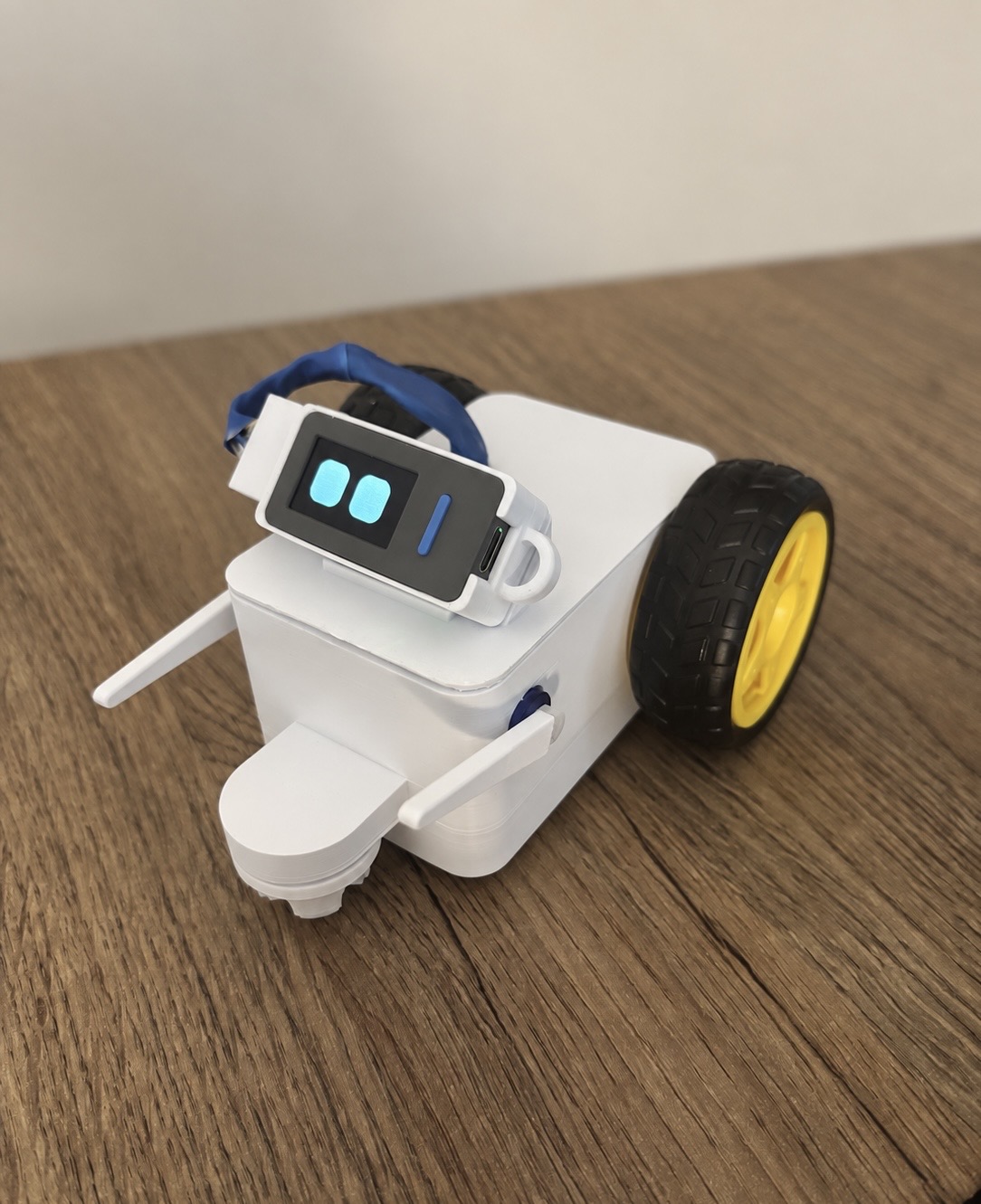
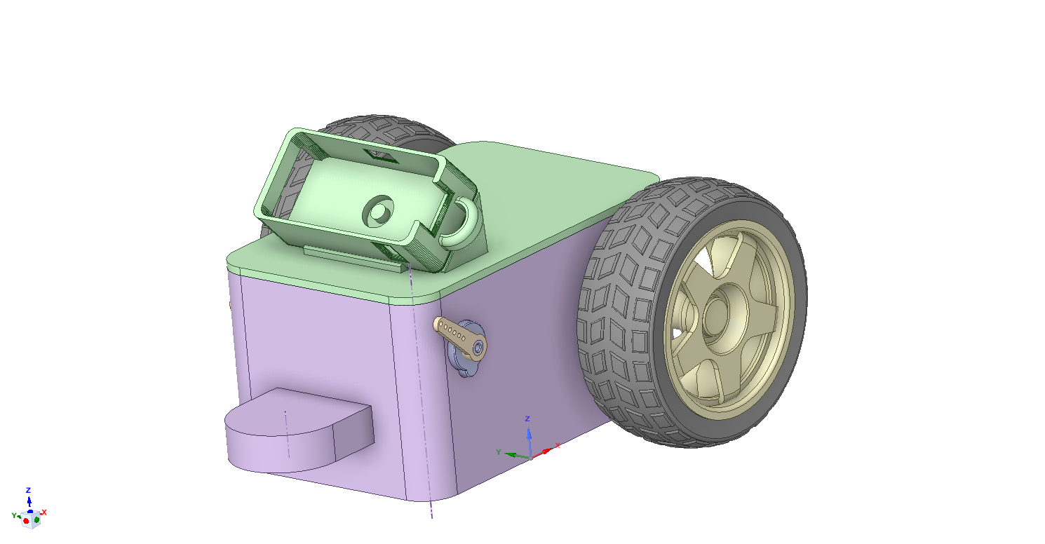
The printed body, assembled · the same assembly in CAD
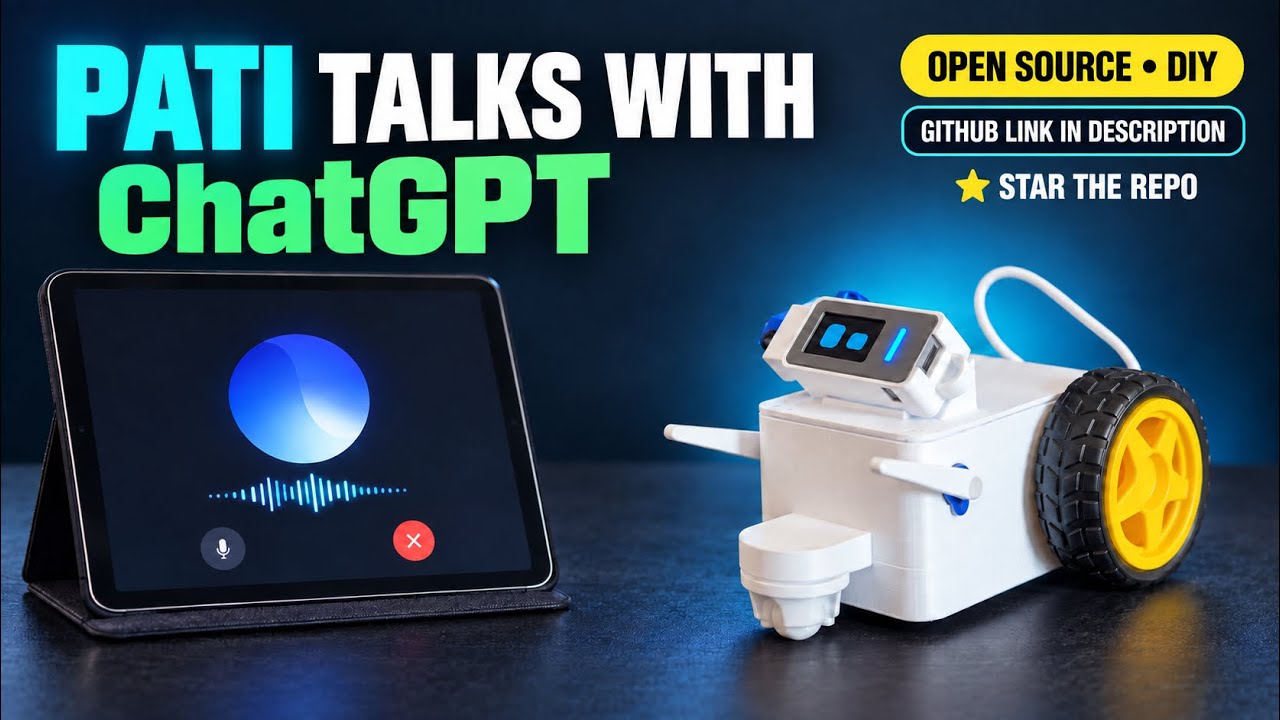
▶ Watch Pati in action
The body is optional and printable — STLs and editable CAD source are in
[`enclosure/`](enclosure/). Without it Pati still talks, listens and
shows its eyes; the body adds two wheels and two arms.
**Status.** Microphone, speaker, display, eyes, Wi-Fi, panel and Gemini
conversation were verified on a real StickS3 on September 1, 2026.
Battery operation is still unstable: speaking can trigger a reset.
The September 5 code review fixed a playback-related eye power-mode bug;
its effect on real battery resets still needs device testing. See
[`firmware/PIL.md`](firmware/PIL.md) for measurements and remaining work.
---
## Layout
```
firmware/ ESP-IDF v5.5 application
panel/ Parent panel — one web page, served from disk during
development and compiled into the firmware for the device
prototype/ Python reference implementation; the host tests compare
firmware behaviour against it
enclosure/ The printable body: STLs ready to slice, editable CAD
source, and the assembly notes
```
The devkit's assembly guide, wiring diagram and printed parts are not
here. They describe hardware that no longer exists, so they live with
it on the `devkit` branch rather than misleading anyone on `main`.
`panel/` is a single source. The page is not duplicated for the device
build, so a firmware update carries the panel with it.
---
## Hardware
One part. **M5Stack StickS3** (SKU K150) — nothing is wired, nothing is
soldered.
| Inside it | |
|---|---|
| ESP32-S3-PICO-1-N8R8 | 8 MB flash, 8 MB octal PSRAM |
| ES8311 | mono audio codec, configured over I2C, one shared I2S bus |
| MEMS microphone | 65 dB SNR |
| AW8737A + 8 Ω 1 W speaker | amplifier enabled through the M5PM1, not from a GPIO |
| ST7789P3 | 135×240 display, used in landscape as 240×135 |
| M5PM1 | power management, battery charging, the power button |
| 250 mAh battery, 2 buttons, BMI270 IMU, IR | 48 × 24 × 15 mm |
Pin assignments have a single source:
[`firmware/main/pati_pinler.h`](firmware/main/pati_pinler.h).
Three things about this board are not obvious and each one fails
silently:
**The microphone, the speaker and the display backlight are not powered
at boot.** They sit on the M5PM1's `L3B` rail, which the Arduino library
turns on during its own init. On bare ESP-IDF nothing turns it on for
you. Miss it and all three are dead while every call still returns
`ESP_OK`. [`pati_guc.cpp`](firmware/main/pati_guc.cpp) does it.
**The microphone and the speaker share one I2S bus, so they share one
sample rate.** Gemini wants 16 kHz in and gives 24 kHz out; neither is
possible directly. The bus runs at 48 kHz and both directions are
resampled — see [Voice](#voice).
**Use the verified ESP32 signal directions:** GPIO14 is output to the
codec (speaker), GPIO16 is input from the codec (microphone). The
peripheral row label led to these being reversed during the first port.
First boot, step by step, with the symptom-to-line mapping for
everything that cannot be checked without the board:
[`firmware/ILK-ACILIS.md`](firmware/ILK-ACILIS.md) (Turkish).
### The previous Pati
Until August 2026 this was a hand-wired ESP32-S3 devkit with an INMP441,
a MAX98357A and a 240×240 display — thirteen soldered wires. It works
and is kept, not deleted:
```
git switch --detach v2.2.8-devkit # source
```
Its built `pati.bin` is in the `v2.2.8` release. The branch also carries
what `main` no longer does: `assembly/REHBER.html` (the soldering guide,
Turkish), the wiring diagram, and **that board's** printed parts — which
are not the ones in [`enclosure/`](enclosure/). Those describe a device
that no longer exists.
⚠️ **Do not run this firmware on that board.** Same chip family, so it
flashes and boots, and the update manifest carries no hardware field. It
refuses to run instead: at boot it probes for the ES8311 and, if absent,
declines to mark itself valid so the bootloader rolls back. That
recovery only exists for an image that arrived over the air — one
flashed by cable has nothing to roll back to.
---
## Body
Pati works on its own. The body is optional: it adds two driven wheels
and two servo arms, and it prints on a home 3D printer. Files, parts
list and assembly notes are in [`enclosure/`](enclosure/).
🔴 **The two front wheels must be ball casters, and they print too**
(`enclosure/print/ball-caster.stl`, print-in-place — the ball comes out
of the printer already turning inside its socket). This is not a styling
choice. With fixed-axle front wheels the chassis sits on a rail: it
rolls freely fore and aft but resists sliding sideways, so the torque
that cannot become rotation escapes along the only unresisted axis and
**Pati creeps forward while turning in place**. Three firmware releases
tried to fix that in software and none of them could — the gesture table
already sums to zero rotation by construction. Swapping the front wheels
ended it.
🔴 **Pati turns in place. It never drives itself anywhere.** There is no
cliff sensor, so a robot that could travel on its own would eventually
walk off a table. The whole gesture system is built around one
guarantee: the two wheels always turn in opposite directions, so net
displacement is zero. Driving across a table is possible only from the
panel, under a child's finger, behind a 600 ms dead-man timer.
🔴 **Motor and servo power never reaches the StickS3.** Every one of the
eight wires from the body to the Stick is either ground or the Stick's
own output; the 6 V rail stays inside the body. This is not a caution
note — it is the reason the pins were chosen that way. With the rule set
up like this, the worst outcome of a wire slipping onto the wrong pin is
"a motor runs continuously", not a dead board.
### Wiring
Wire colors in both diagrams match the real assembly. Same diagram, two
languages — the parts and pin numbers are identical.
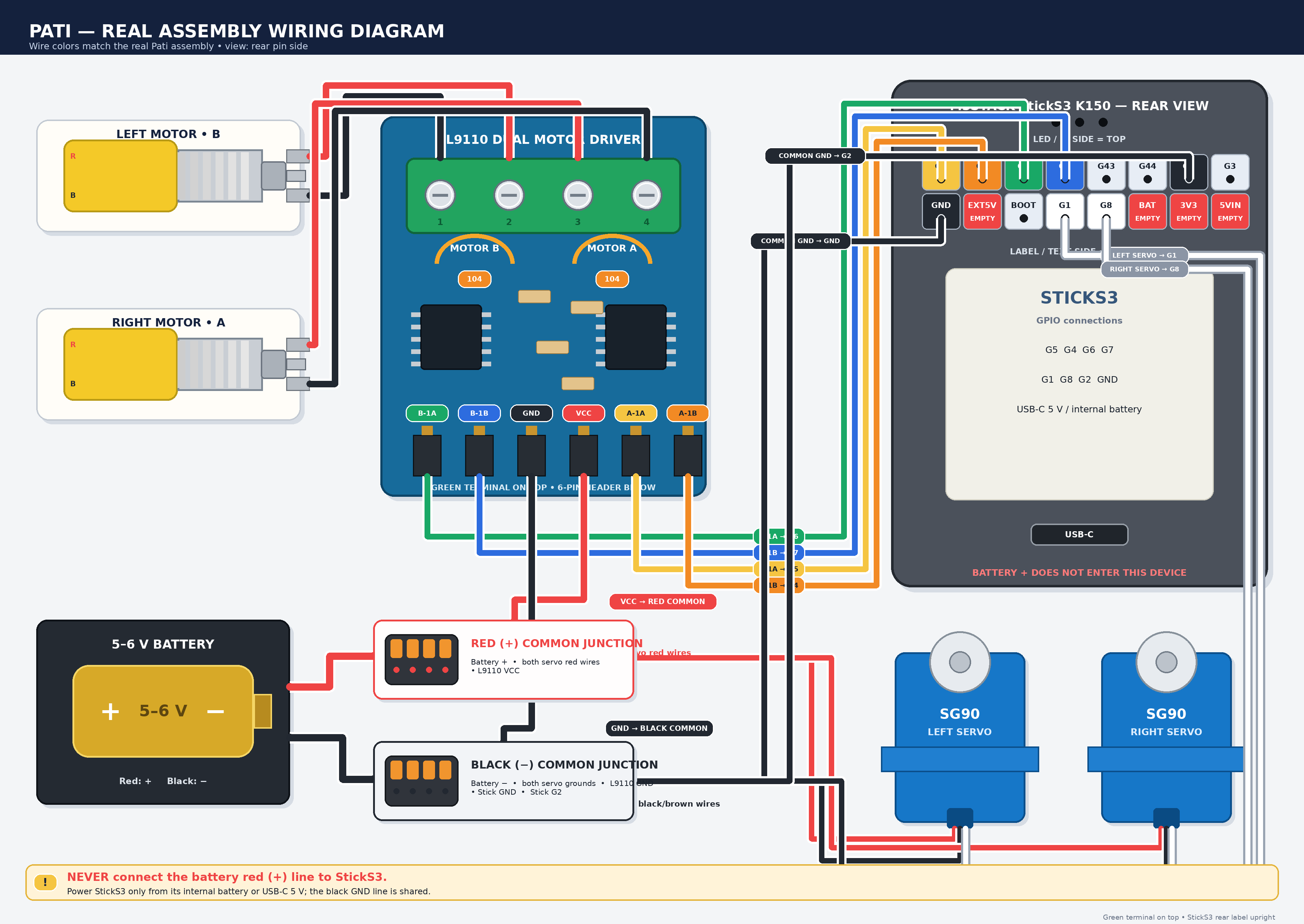
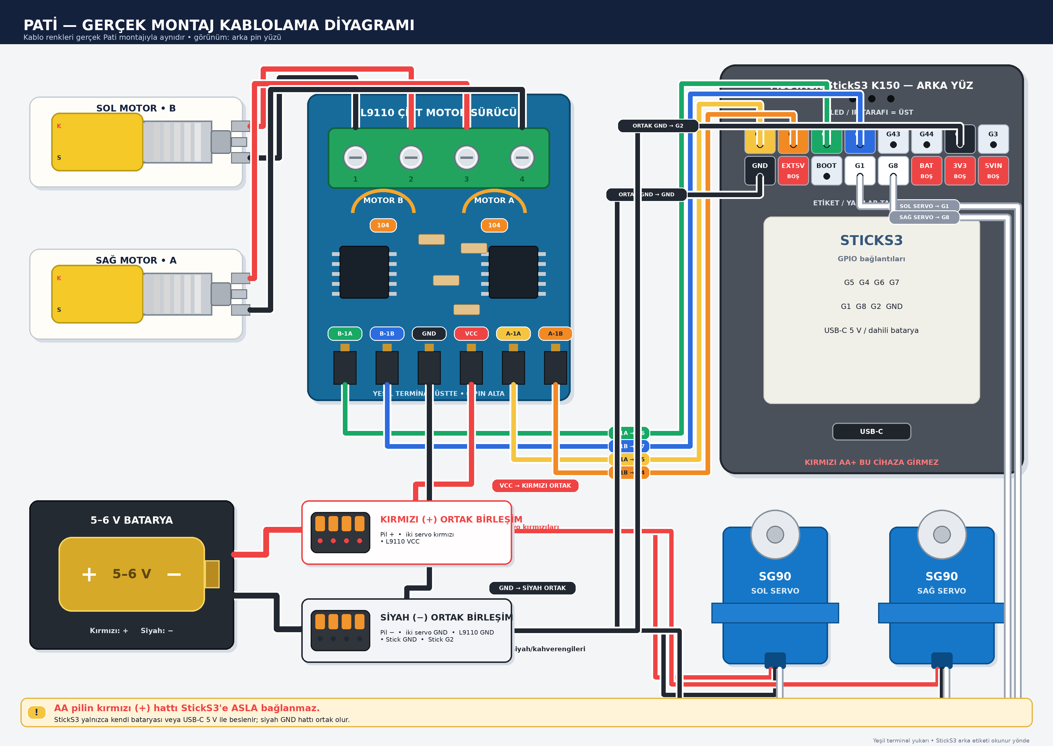
There is a third, different document:
[`firmware/Pati_Tek_Bakis_Kablolama_Diyagrami.png`](firmware/Pati_Tek_Bakis_Kablolama_Diyagrami.png)
(Turkish) is not another copy of these — it is the step-by-step pin
table: which way to hold the connector, the L9110 pin map, the power
junctions, and the first-power-up checklist. Use the diagrams above to
see *where the wires go*, and that one to check *each pin before
switching on*.
Pin assignments, commissioning measurements and the numbers still
waiting to be measured: [`firmware/BEDEN.md`](firmware/BEDEN.md)
(Turkish).
---
## Build
Requires ESP-IDF v5.5. On Windows use PowerShell — `idf_tools.py`
refuses to run under MSYS.
```
. "$IDF_PATH/export.ps1"
cd firmware
idf.py -p flash monitor
```
Nothing to fill in first. The Wi-Fi credentials and the Gemini key are
both entered on the device — the first through the captive portal, the
second through the panel.
`firmware/KARTA-YUKLE.bat` does the same on Windows and finds the
serial port itself.
No API key is built in. The Gemini key is entered from the parent panel
and stored on the device, so the image contains no secret and can be
published. The partition table is custom
([`firmware/partitions.csv`](firmware/partitions.csv)) and must be
written over USB — `idf.py flash`, not `app-flash`.
## Updates
Push. GitHub builds the firmware and publishes a release holding
`pati.bin` and a generated `surum.json`; the device polls the latter and
downloads the former. No update server, no companion app, nothing to
upload by hand. Details in
[`firmware/SURUM-NASIL-CIKARILIR.md`](firmware/SURUM-NASIL-CIKARILIR.md).
CI picks the version rather than asking for it: the patch of the last
release, plus one. A larger number written into
[`firmware/surum.txt`](firmware/surum.txt) by hand is honoured, a
smaller one ignored. The line under it is the single sentence the parent
sees, and a release with no note is refused.
Publishing on every push is deliberate here. Forgetting to raise a
version produced no error and no release — the robot simply stayed
behind and nothing said so. A push to this repository means the change
was tested and is meant to reach the child's room, so that is what it
does. Only `firmware/` and `panel/` trigger it, since only those end up
in the image.
The manifest is a release asset rather than a committed file because a
push publishes a committed file immediately but does not build the
binary. For the minutes in between, the panel would offer an update that
404s. Sharing a release makes the manifest unable to exist before the
image it describes.
The binary is not committed. The panel is compiled into it, so a panel
change ships as a firmware update — which is why the two cannot drift.
The build needs no secrets, which is what makes CI possible at all: the
key and the Wi-Fi credentials both live in the device's NVS, and no
source file reads them from the configuration.
Rollback is enabled: a new image boots on trial and is only marked good
once the network stack and panel are up. An image that cannot get that
far is reverted by the bootloader on the next power cycle.
---
## Voice
Pati sounds like a child. That is not a Gemini setting — the Live API
exposes no pitch or rate control, only a voice name. Puck's raw voice is
an adult man's. The character comes entirely from **playing the reply
1.30× fast**, which raises the pitch by about the same amount.
On the old board this was one line: run the speaker's I2S clock at
31 200 Hz instead of 24 000. The StickS3 cannot do that — the speaker
shares its clock with the microphone, and moving it would break capture.
So the multiplier moved into software. The bus runs at 48 kHz and every
output sample steps `çarpan / 2` through the 24 kHz source — 0.65 at
1.30× — interpolating between samples. The step is always below 1
across the whole adjustable range (0.80–1.60 → 0.40–0.80), which is the
point: below 1 you interpolate and nothing aliases. Above 1 you would be
decimating, and Pati would rasp.
Capture goes the other way: 48 kHz down to the 16 kHz Gemini wants, an
exact 3:1 ratio, averaging each group of three. The averaging is also a
crude low-pass, which plain decimation would not be.
[`pati_ornekleyici.hpp`](firmware/main/pati_ornekleyici.hpp) holds the
maths, and it is a header rather than part of `pati_ses.cpp` because the
host test includes the same file — the test measures the real code, not
a copy. It found two real defects: output drifting apart depending on
how the audio was sliced, and phase loss over a long stream. Both came
from accumulating position in a single `float`, whose precision decays
as the value grows. Position is now an integer index plus a fraction
kept in `[0, 1)`.
---
## Tests
```
firmware/test/derle.bat C++ eye renderer vs. the browser renderer,
pixel by pixel; C++ memory engine vs. Python;
the resampler that produces Pati's voice
python prototype/testler.py prototype behaviour
node panel/panel_test.mjs the panel loads against a stub DOM, in each
of the four sample data sets
```
`ses_karsilastir` also writes two WAVs from a raw 24 kHz Gemini capture,
for listening rather than asserting:
```
firmware/test/ses_karsilastir.exe --pcm kayit.pcm --cikti .
```
One is what the old board played, the other is what the new path
produces. They have to sound the same.
The panel check exists because a missing element makes `querySelector`
return null, and the resulting throw stops the module — so the failure
is not the card that was edited, it is every card below it. Nothing on
screen says why.
The host comparisons exist because a port that compiles is not a port
that behaves identically. Generated headers are produced by
`prompt_uret.py` and `goz_uret.mjs`, which read their output back and
compare it to the source; they are not edited by hand.
---
## Operation
With no reachable saved network the device opens its own access point
and serves a captive portal for Wi-Fi setup. Once connected it
advertises itself over mDNS and the panel is reachable at `pati.local`.
The panel covers voice and rate, response latency, sleep threshold,
usage and estimated cost, the robot's name, the facts it has retained,
the Gemini key, and firmware updates. The interface is Turkish only.
Setup is Wi-Fi, then the key. Until a key is entered the robot has a
face but no voice, and the panel says so rather than leaving the parent
to guess.
When Google rejects a request the panel distinguishes the cases, because
the parent's next action differs: a rejected key needs replacing, an
exhausted quota needs credit, and an unreachable network needs nothing
at all. Collapsing the three would invite paying for an outage.
---
## Privacy
No child data is committed here. API keys, Wi-Fi credentials, retained
memory, usage counters and transcripts are excluded by `.gitignore`.
On the device, memory is stored in NVS and written atomically, since
the expected shutdown is a power cut. It can be cleared from the panel.
---
## License
MIT — see [LICENSE](LICENSE), which also lists third-party components.