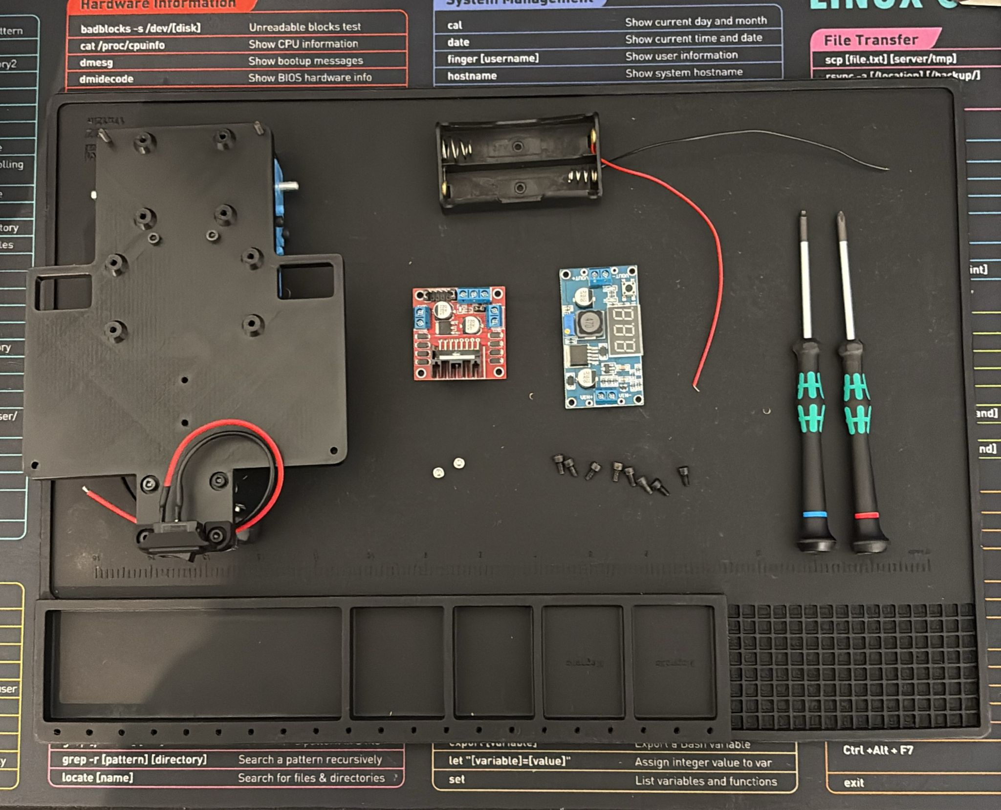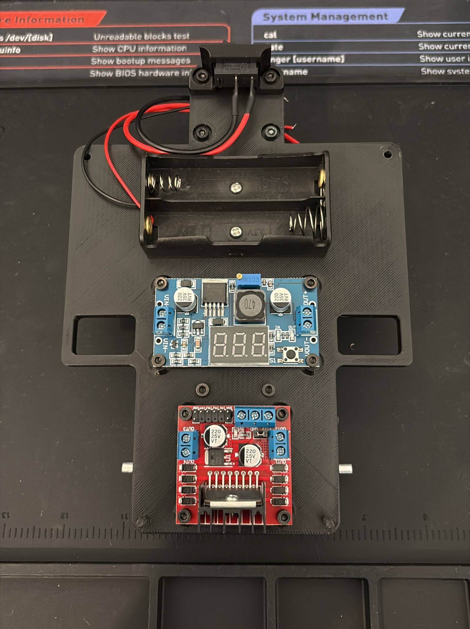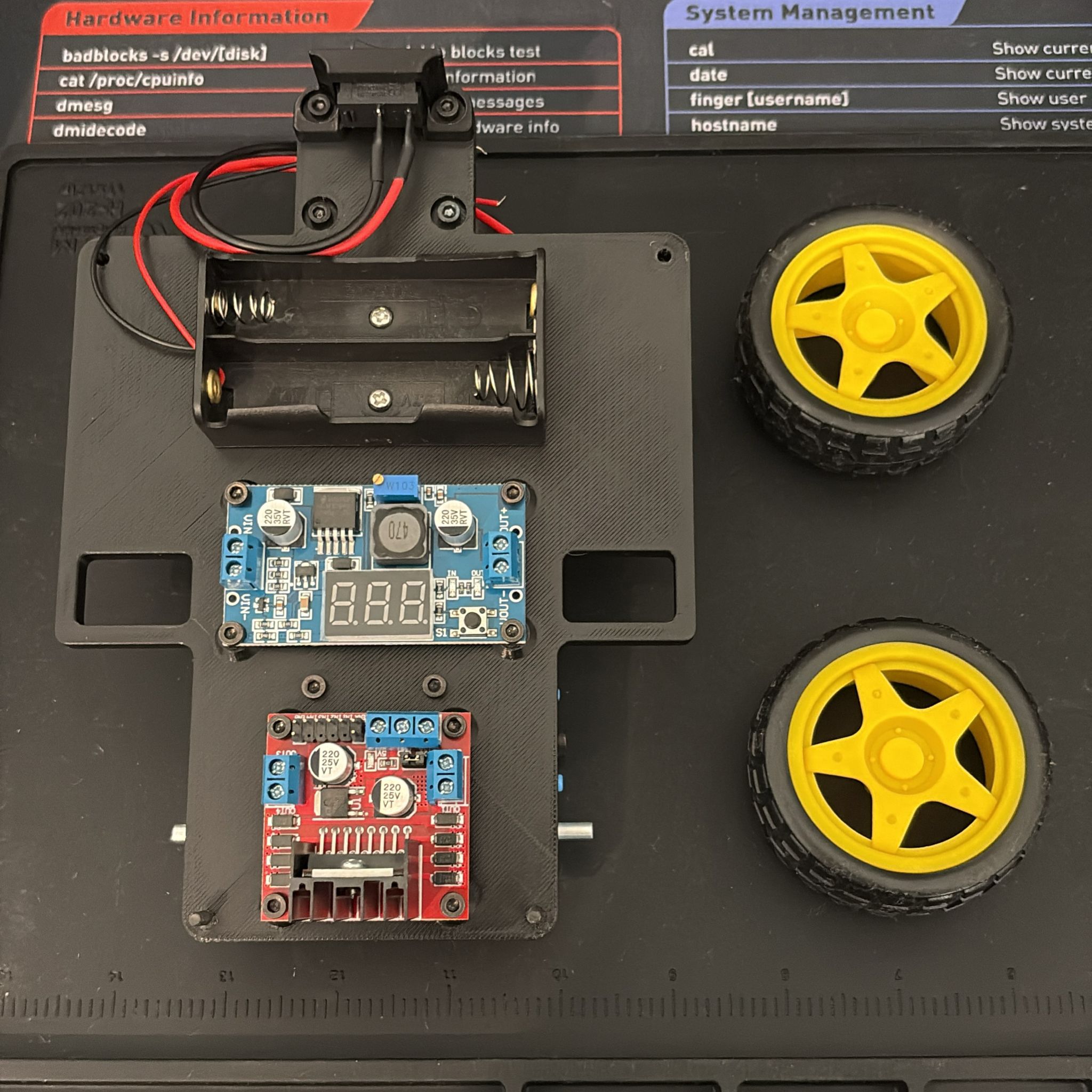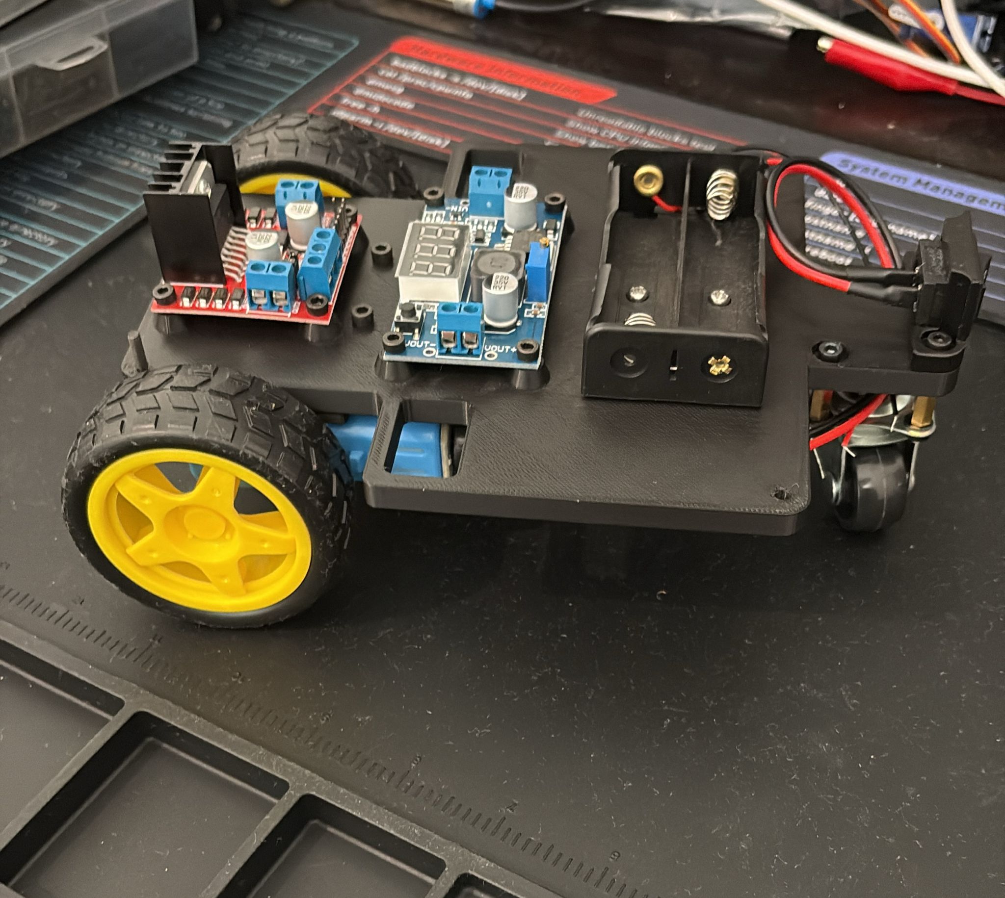
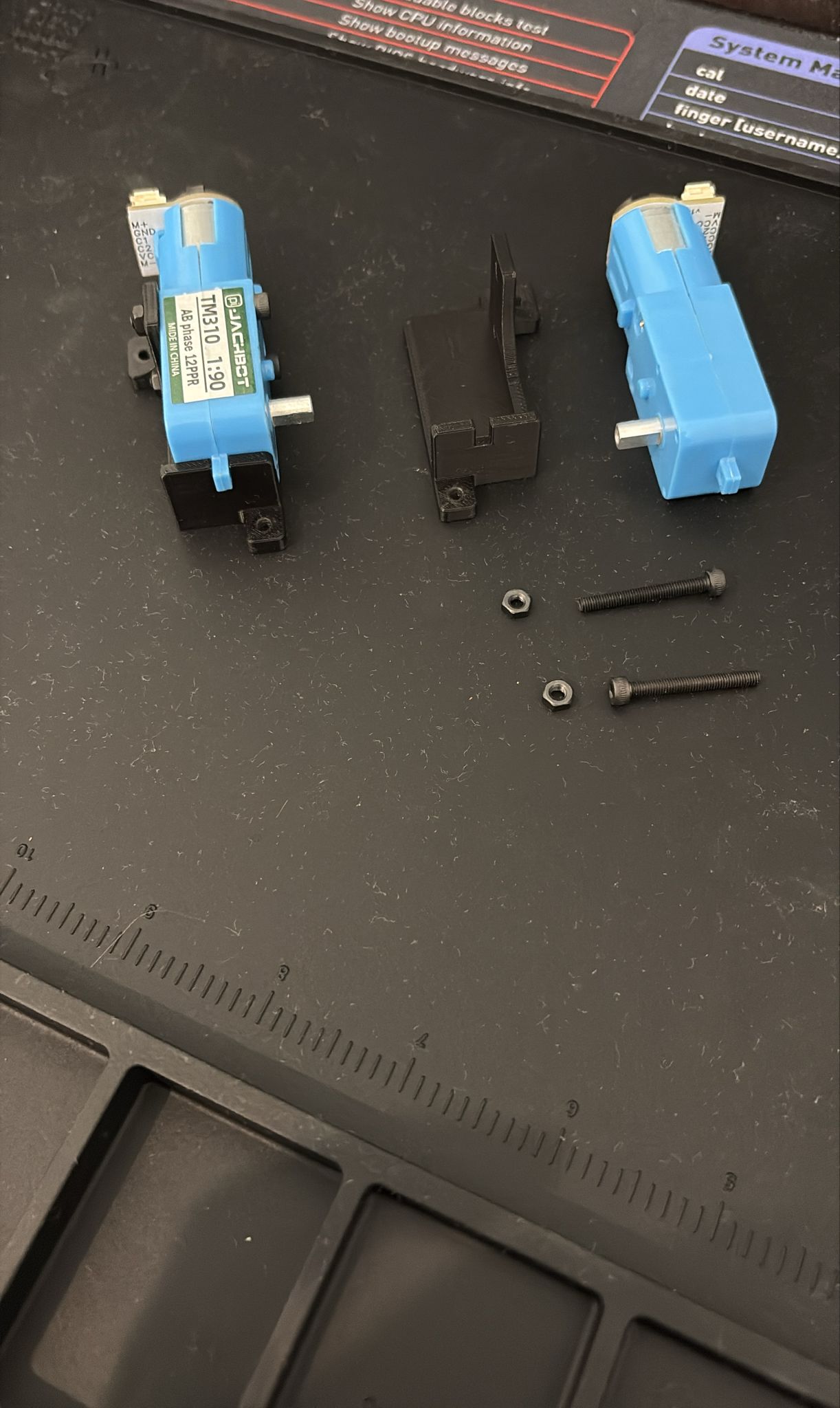
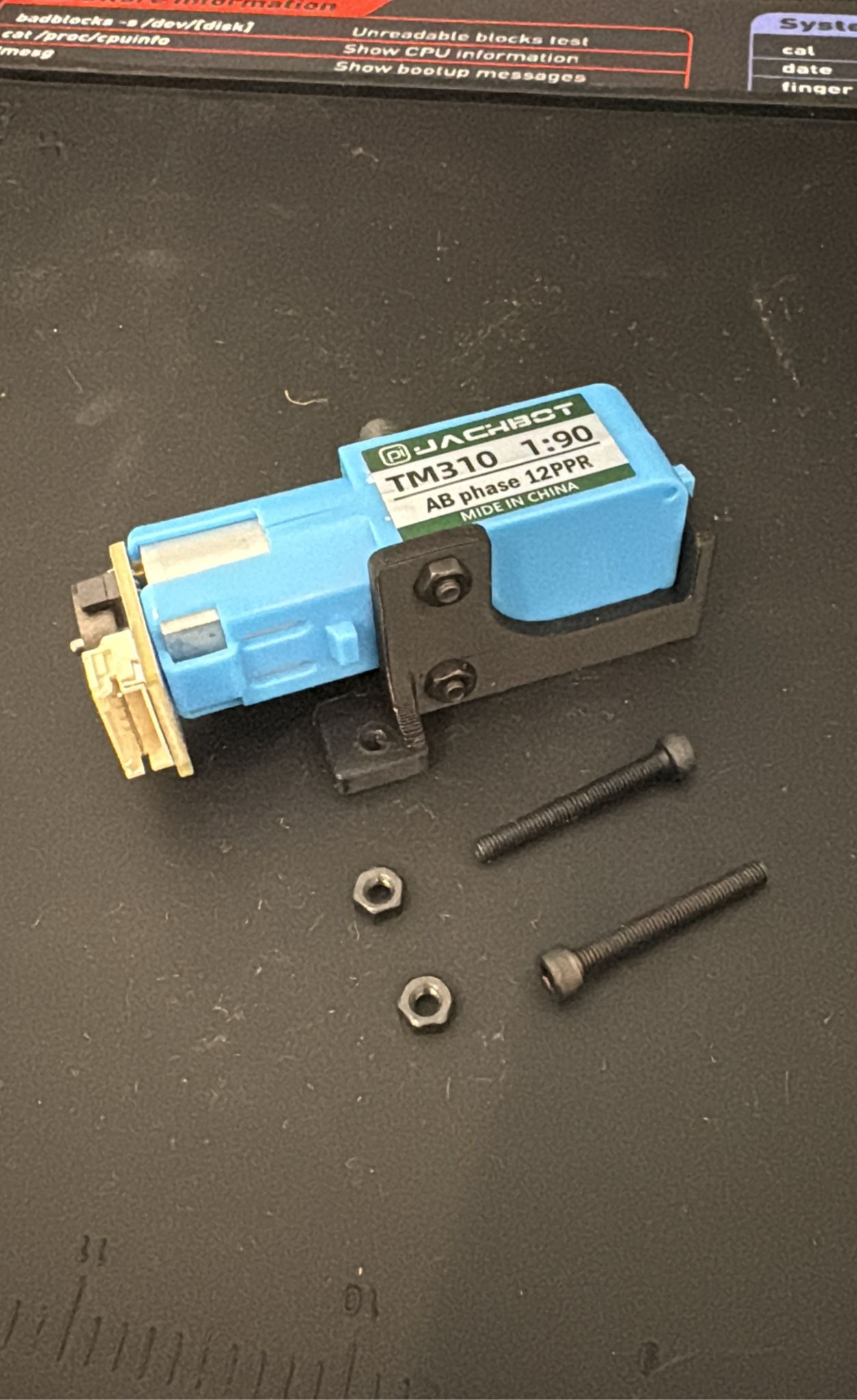
 ## Step 1: Attach Motors to Motor Mounts
| Hardware | Qty |
|----------|-----|
| Motor mounts (3D printed) | 2 |
| M3x24 screws | 4 |
| M3 nuts | 4 |
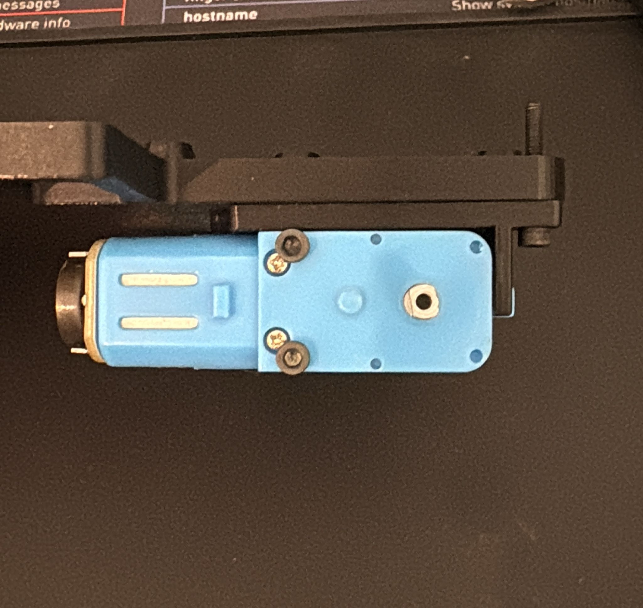
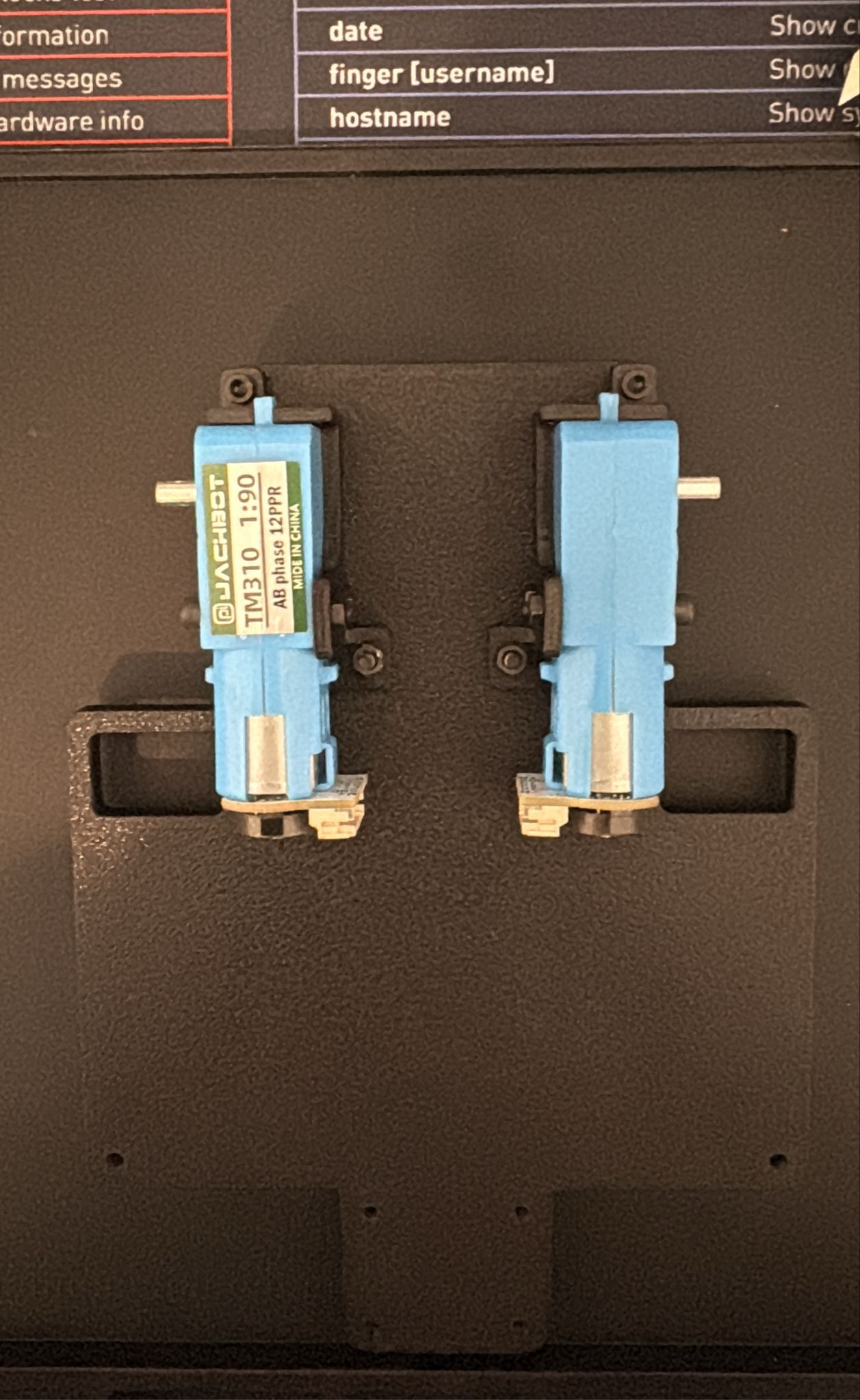
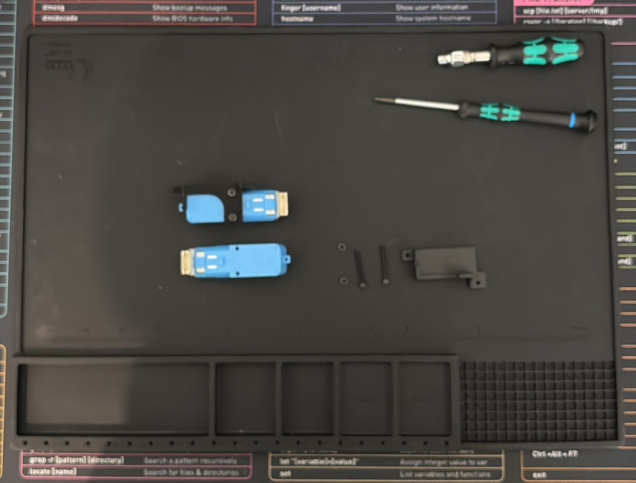
1. Slide each DC motor into its 3D-printed motor mount bracket.
2. Secure each motor with 2 screws and nuts.
## Step 1: Attach Motors to Motor Mounts
| Hardware | Qty |
|----------|-----|
| Motor mounts (3D printed) | 2 |
| M3x24 screws | 4 |
| M3 nuts | 4 |
1. Slide each DC motor into its 3D-printed motor mount bracket.
2. Secure each motor with 2 screws and nuts.
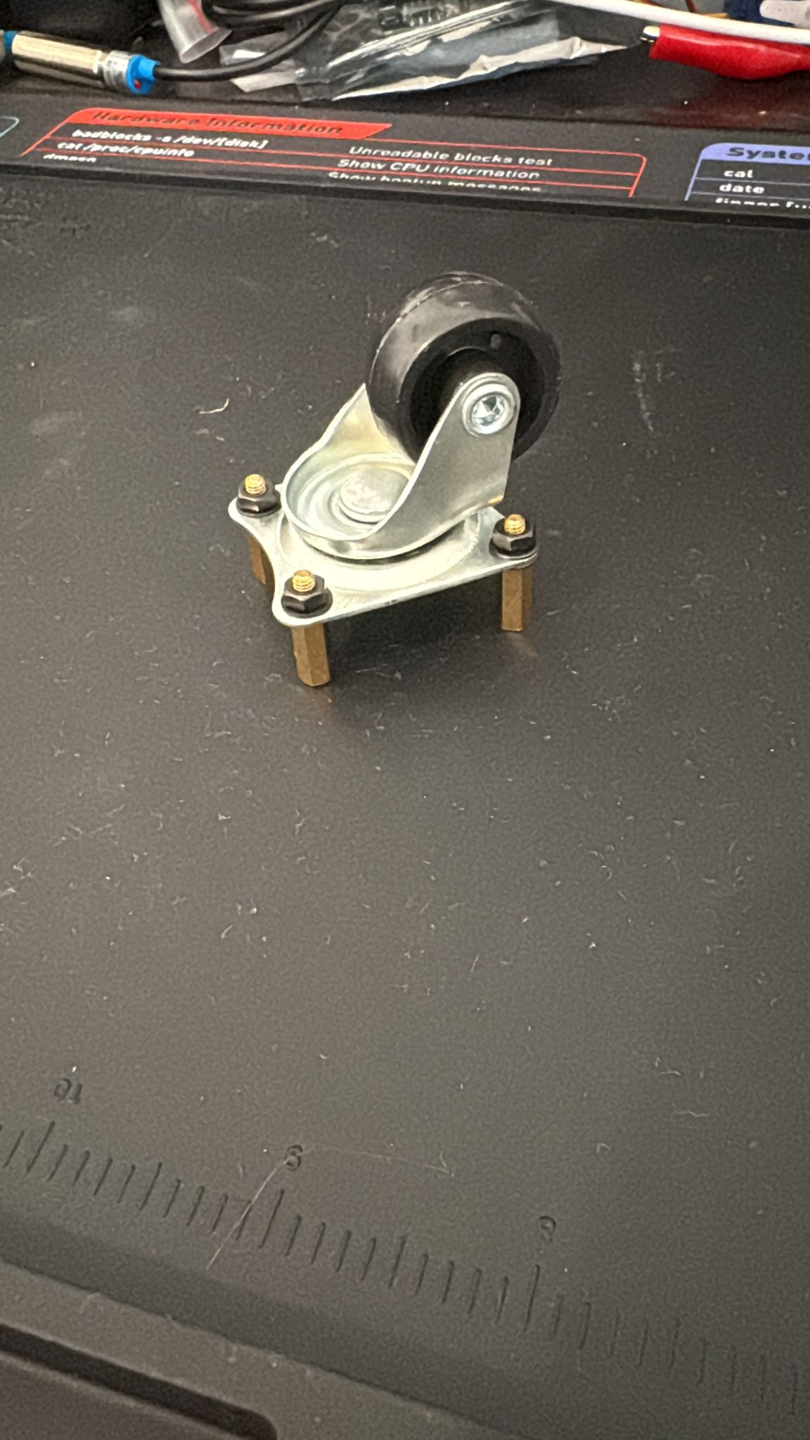
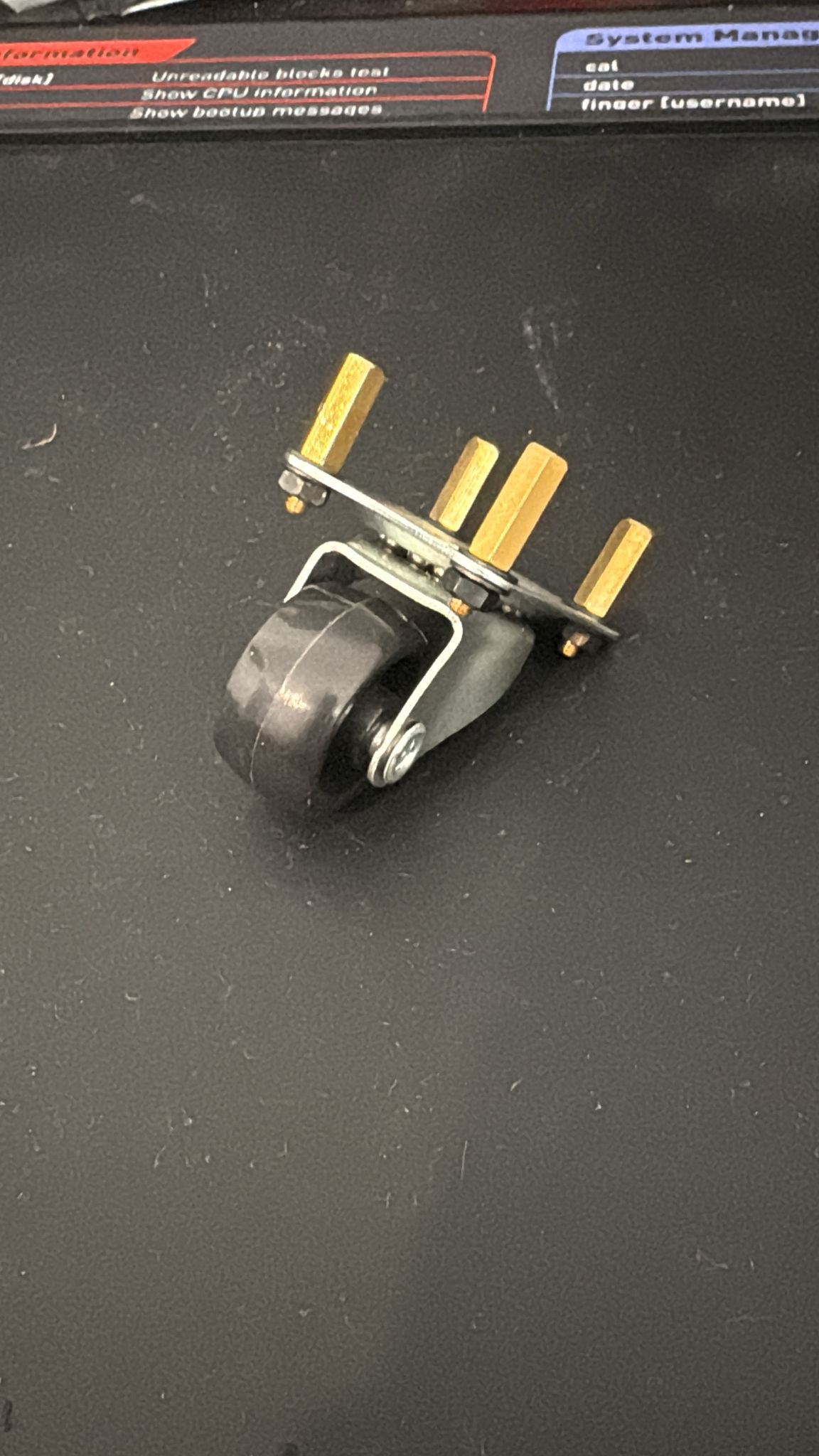
 ## Step 3: Assemble the Caster Wheel
| Hardware | Qty |
|----------|-----|
| Caster wheel | 1 |
| M3x12 standoffs (female-male) | 4 |
| M3 shims | 4 |
| M3 nuts | 4 |
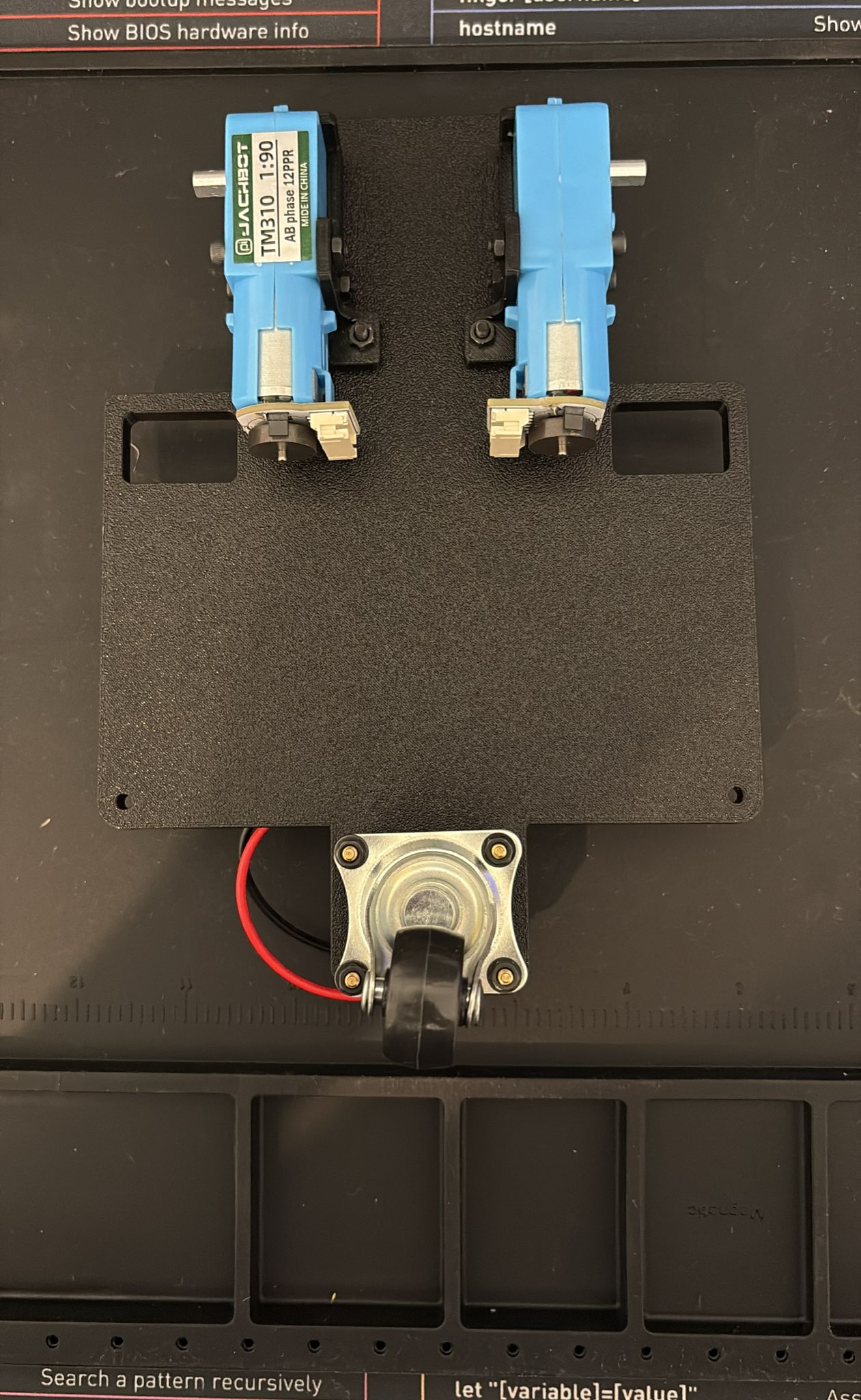
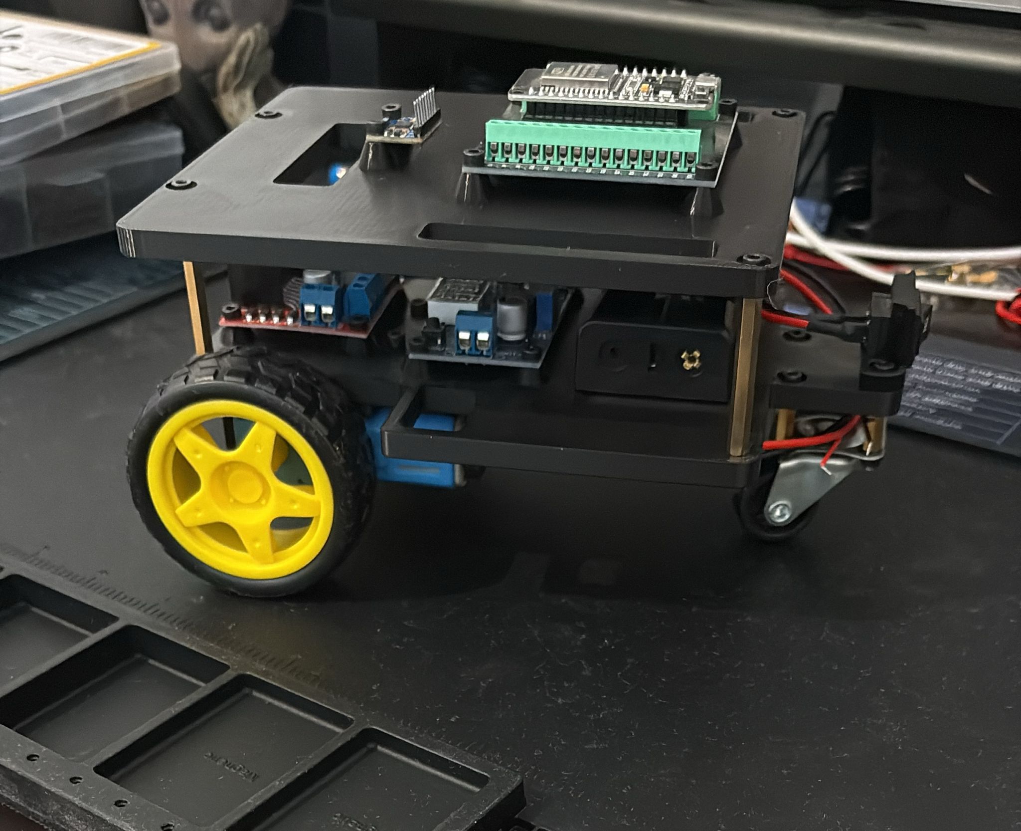
1. Attach the caster wheel to its mounting plate using screws and nuts.
2. Screw the standoffs into the caster plate, these will later connect to the base plate.
## Step 3: Assemble the Caster Wheel
| Hardware | Qty |
|----------|-----|
| Caster wheel | 1 |
| M3x12 standoffs (female-male) | 4 |
| M3 shims | 4 |
| M3 nuts | 4 |
1. Attach the caster wheel to its mounting plate using screws and nuts.
2. Screw the standoffs into the caster plate, these will later connect to the base plate.
 ### Step 4.1: Mount Motors to Base Plate
| Hardware | Qty |
|----------|-----|
| M3x20 screws | 2 |
| M3x16 screws | 2 |
| M3 nuts | 2 |
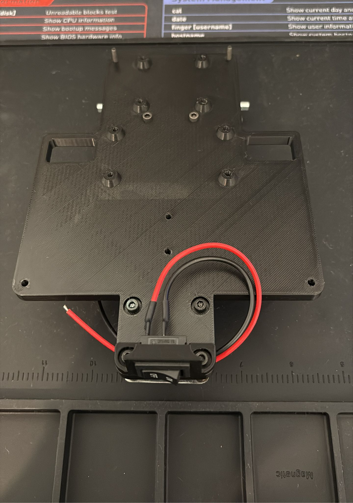
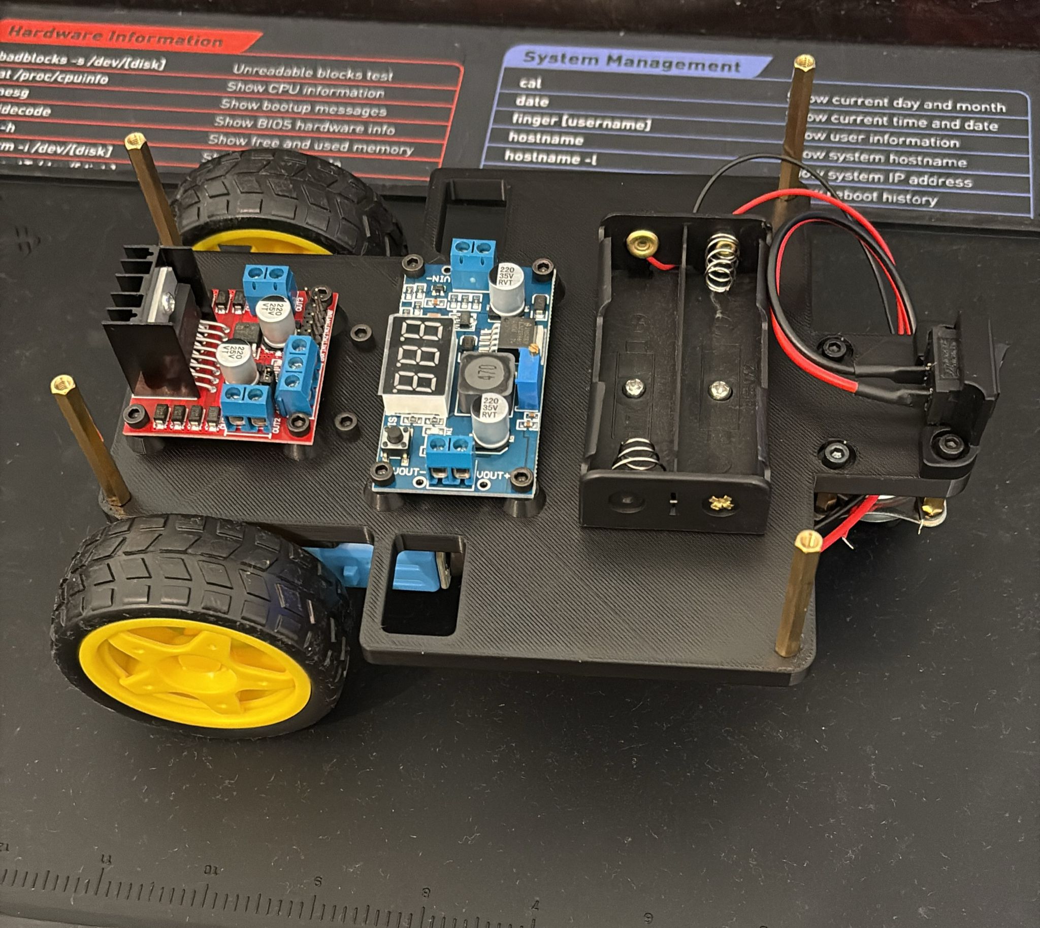
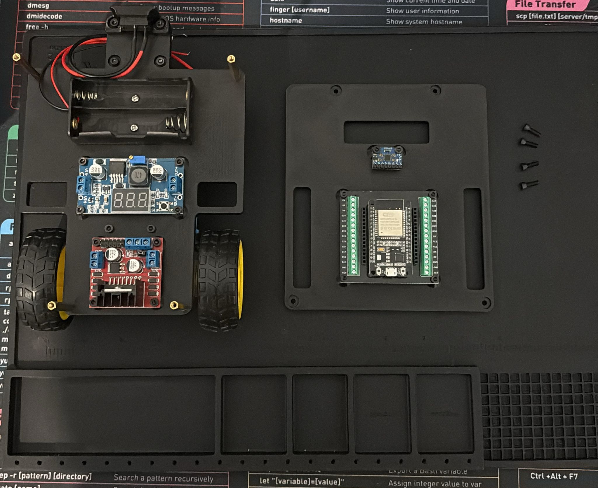
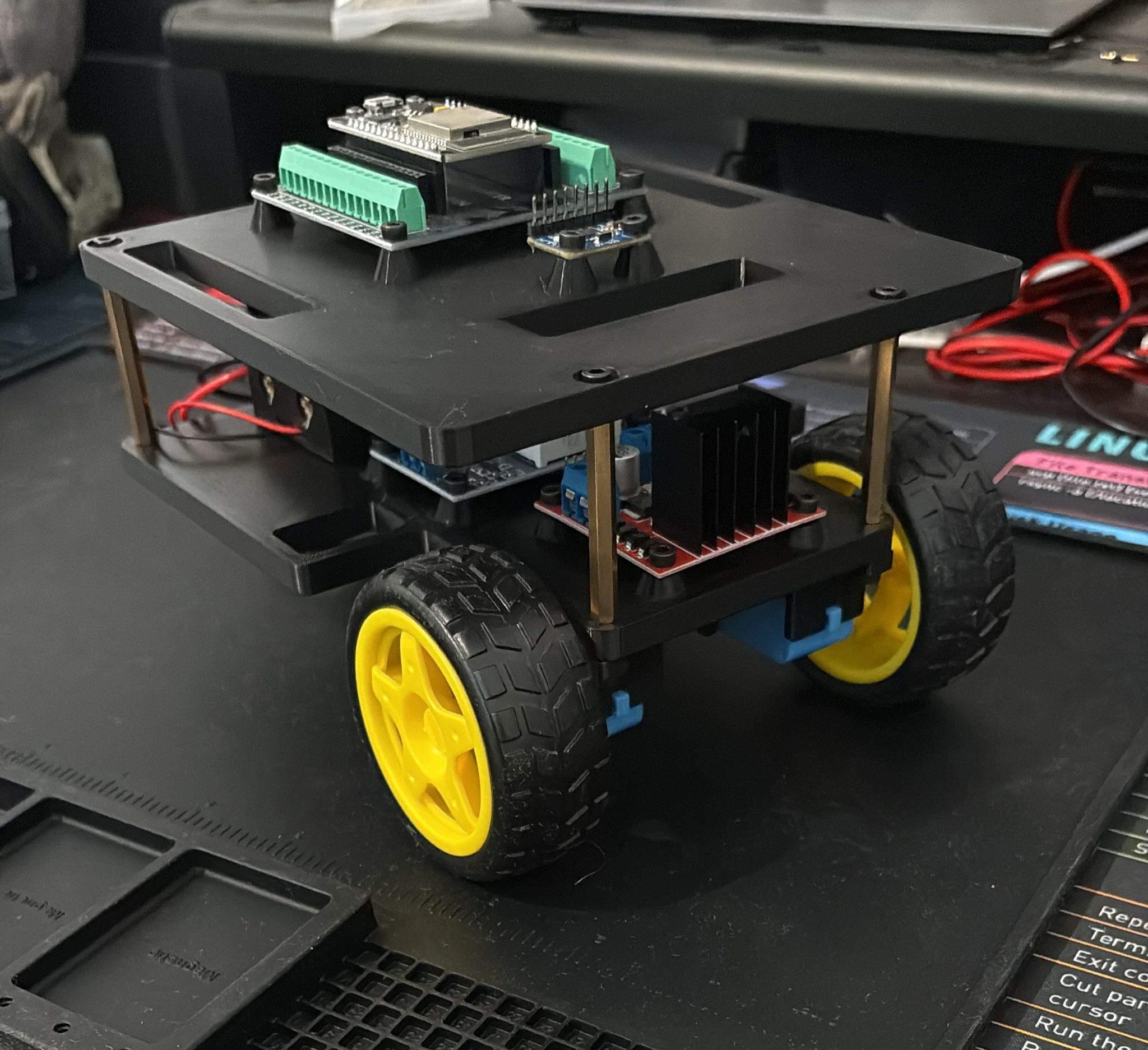
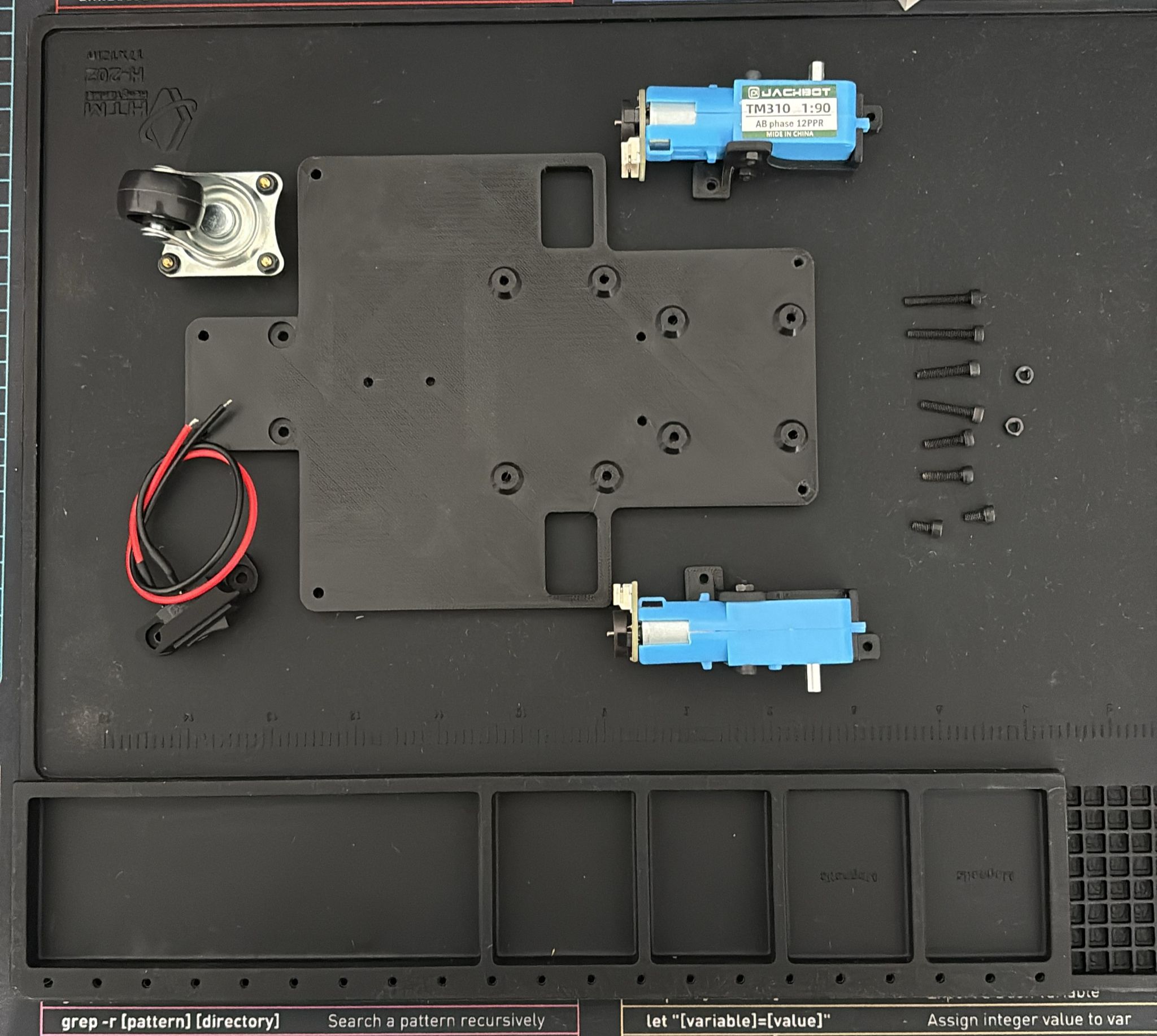
1. Slide the motor mount brackets into the base plate slots from the bottom.
2. Secure each motor mount with the M3x16 screws and nuts.
3. Insert the M3x20 screws facing **upwards** through the base plate - no nuts needed, these will thread into the standoffs later.
### Step 4.1: Mount Motors to Base Plate
| Hardware | Qty |
|----------|-----|
| M3x20 screws | 2 |
| M3x16 screws | 2 |
| M3 nuts | 2 |
1. Slide the motor mount brackets into the base plate slots from the bottom.
2. Secure each motor mount with the M3x16 screws and nuts.
3. Insert the M3x20 screws facing **upwards** through the base plate - no nuts needed, these will thread into the standoffs later.