
 *A clean somersault · CyberBionic Maker*
*A clean somersault · CyberBionic Maker*
*A clean somersault · CyberBionic Maker*
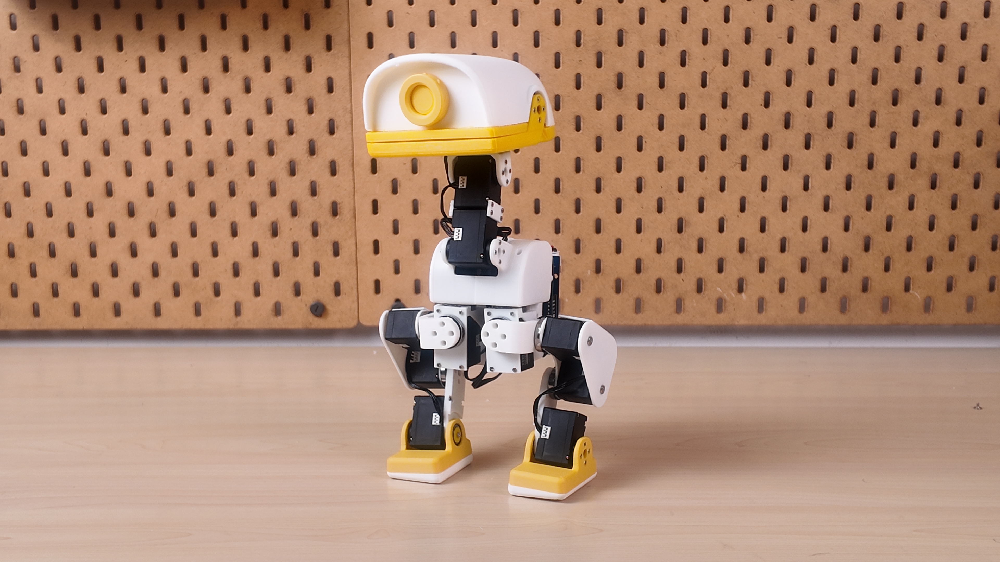 *XGO-Duck prototype — printed parts, articulated legs, and a movable head and beak.*
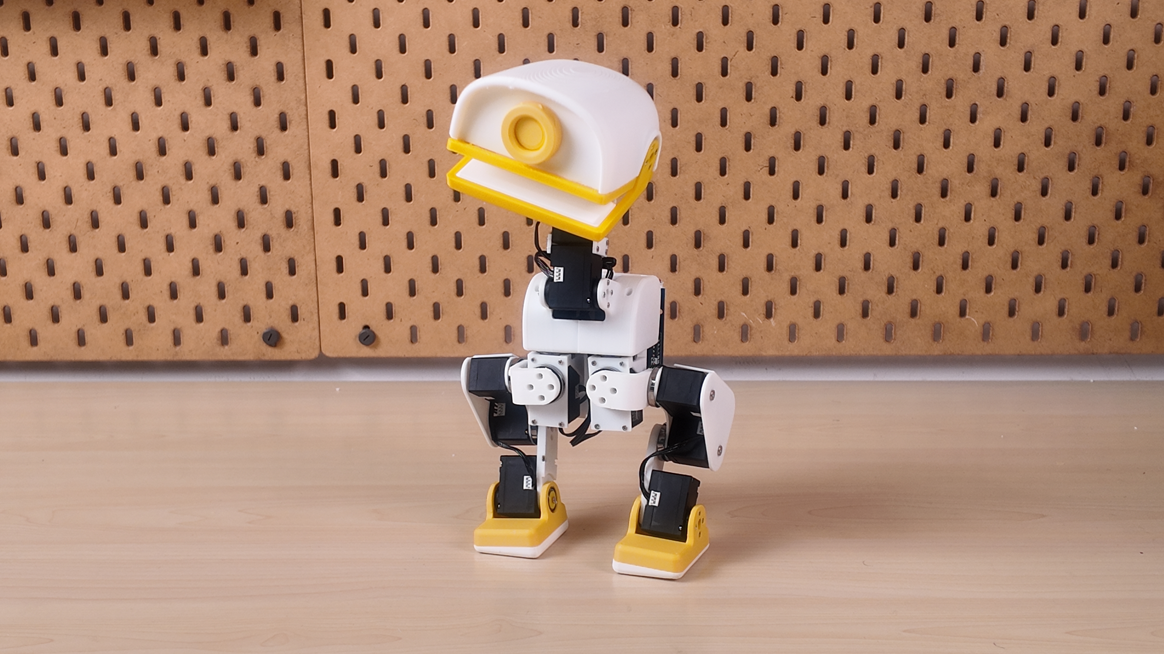 A movable head and beak Four neck/head joints and a separate mouth servo. |
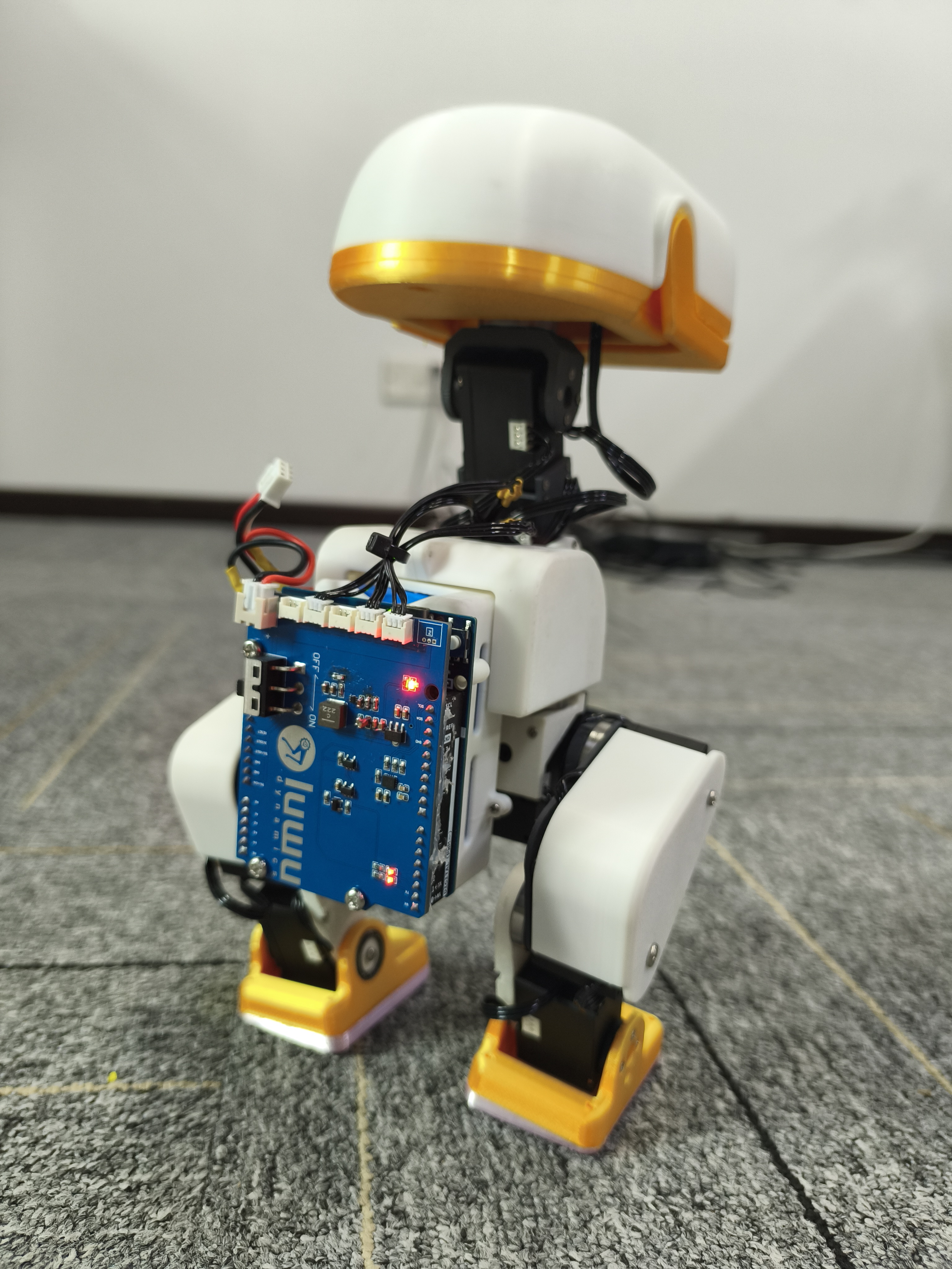 Electronics you can inspect Rear-mounted controller stack and accessible wiring. |
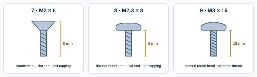
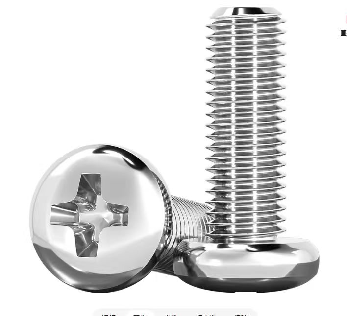 *Item 9 has the domed top shown here. Item 8 has the same rounded sides but a flat top. The photo is a head-style reference, not a size or thread specification.*
### 2. Print the structure
Download the models from [structure/](structure/). The filenames carry useful assembly information:
| Filename pattern | Meaning | Example |
| --- | --- | --- |
| `2x_` | Print two copies | `2x_shank.stl` |
| `left_` / `right_` | Separate left and right parts | `left_foot.stl`, `right_foot.stl` |
| `tpu` | Flexible part | `2x_foot_bottom_tpu.stl`, `mouth_up_tpu.stl` |
Use the [print inventory](docs/PRINTING.md) to track parts. Test a servo mount and bearing fit before printing the full set; a complete validated print profile is still to be documented.
### 3. Configure servos and assemble
Prepare each servo's ID and center position using the [runtime setup instructions](https://github.com/LuwuDynamics/xgoduck_runtime_arduino#first-time-servo-setup), then follow [Assembly_Guide.pdf](Assembly_Guide.pdf).
| Assembly reference | Focus |
| --- | --- |
| Page 1 | Servo ID placement |
| Pages 2–5 | Shaft preparation, initial structure and cable routing |
| Pages 6–15 | Legs, feet and soles |
| Pages 16–23 | Head and neck mechanisms |
| Pages 24–25 | Final assembly |
The [build guide](docs/BUILD_GUIDE.md) adds preparation and inspection checkpoints. Configure one servo at a time, label its ID, and leave cable clearance through each joint's movement.
### 4. Calibrate and bring it to life
Install the [onboard runtime](https://github.com/LuwuDynamics/xgoduck_runtime_arduino), verify servo and IMU feedback, and complete calibration with the robot supported. Start with the default pose before motion trials.
The runtime includes **walk, get-up and pick policies**, plus separate mouth control. Their behavior depends on the assembled hardware, calibration and test conditions. Using the bundled policies does not require training a new model.
## Hardware files
| Path | Contents |
| --- | --- |
| [Assembly_Guide.pdf](Assembly_Guide.pdf) | 25-page illustrated assembly reference |
| [BOM.md](BOM.md) | Whole-robot purchasing list, supplier links and battery reference image |
| [structure/](structure/) | Printable STL models |
| [PCBA/ArduinoUnoQ.SchDoc](PCBA/ArduinoUnoQ.SchDoc) | Altium schematic source |
| [PCBA/ArduinoUnoQ.PcbDoc](PCBA/ArduinoUnoQ.PcbDoc) | Altium PCB source |
| [PCBA/ArduinoUnoQ.pdf](PCBA/ArduinoUnoQ.pdf) | Board layout and dimension drawing |
| [PCBA/ArduinoUnoQ.DWG](PCBA/ArduinoUnoQ.DWG) · [STEP model](PCBA/ArduinoUnoQ.step) | Board outline and mechanical integration model |
| [PCBA/BOM.xlsx](PCBA/BOM.xlsx) · [Pick-and-place data](PCBA/Pick%20Place%20for%20ArduinoUnoQ.csv) | Expansion-board assembly materials and placement coordinates |
| [docs/](docs/) | Build, printing, BOM and troubleshooting notes |
## From hardware to your own behavior
| Repository | Purpose |
| --- | --- |
| **[xgoduck_hardware](https://github.com/LuwuDynamics/xgoduck_hardware)** | Mechanical parts, electronics, BOM and assembly |
| **[xgoduck_runtime_arduino](https://github.com/LuwuDynamics/xgoduck_runtime_arduino)** | UNO Q firmware, policy execution, browser setup and control |
| **[xgoduck_rl](https://github.com/LuwuDynamics/xgoduck_rl)** | Simulation, reinforcement-learning training and policy export |
Keep the hardware, runtime and policy revisions together in your build record. This makes it easier to reproduce a working configuration and diagnose changes.
## Origins and contributions
XGO-Duck builds on [Microduck](https://github.com/pollen-robotics/microduck) and [microduck_rl](https://github.com/pollen-robotics/microduck_rl) by **Pollen Robotics**. The duck form, 15-servo arrangement and policy joint order originate in that work. Luwu Dynamics' adaptation focuses on **Arduino UNO Q, Feetech 1910 servos, the custom expansion board, and the matching software/model integration**. See [origins and adaptations](UPSTREAM.md).
Build reports, tested print settings, clearer assembly photos and reproducible fixes are welcome. Read [CONTRIBUTING.md](CONTRIBUTING.md) or [open an issue](https://github.com/LuwuDynamics/xgoduck_hardware/issues).
For reuse terms, consult [LICENSING.md](LICENSING.md) and the applicable file-level notices. Contact: **hello@xgorobot.com**.
*Item 9 has the domed top shown here. Item 8 has the same rounded sides but a flat top. The photo is a head-style reference, not a size or thread specification.*
### 2. Print the structure
Download the models from [structure/](structure/). The filenames carry useful assembly information:
| Filename pattern | Meaning | Example |
| --- | --- | --- |
| `2x_` | Print two copies | `2x_shank.stl` |
| `left_` / `right_` | Separate left and right parts | `left_foot.stl`, `right_foot.stl` |
| `tpu` | Flexible part | `2x_foot_bottom_tpu.stl`, `mouth_up_tpu.stl` |
Use the [print inventory](docs/PRINTING.md) to track parts. Test a servo mount and bearing fit before printing the full set; a complete validated print profile is still to be documented.
### 3. Configure servos and assemble
Prepare each servo's ID and center position using the [runtime setup instructions](https://github.com/LuwuDynamics/xgoduck_runtime_arduino#first-time-servo-setup), then follow [Assembly_Guide.pdf](Assembly_Guide.pdf).
| Assembly reference | Focus |
| --- | --- |
| Page 1 | Servo ID placement |
| Pages 2–5 | Shaft preparation, initial structure and cable routing |
| Pages 6–15 | Legs, feet and soles |
| Pages 16–23 | Head and neck mechanisms |
| Pages 24–25 | Final assembly |
The [build guide](docs/BUILD_GUIDE.md) adds preparation and inspection checkpoints. Configure one servo at a time, label its ID, and leave cable clearance through each joint's movement.
### 4. Calibrate and bring it to life
Install the [onboard runtime](https://github.com/LuwuDynamics/xgoduck_runtime_arduino), verify servo and IMU feedback, and complete calibration with the robot supported. Start with the default pose before motion trials.
The runtime includes **walk, get-up and pick policies**, plus separate mouth control. Their behavior depends on the assembled hardware, calibration and test conditions. Using the bundled policies does not require training a new model.
## Hardware files
| Path | Contents |
| --- | --- |
| [Assembly_Guide.pdf](Assembly_Guide.pdf) | 25-page illustrated assembly reference |
| [BOM.md](BOM.md) | Whole-robot purchasing list, supplier links and battery reference image |
| [structure/](structure/) | Printable STL models |
| [PCBA/ArduinoUnoQ.SchDoc](PCBA/ArduinoUnoQ.SchDoc) | Altium schematic source |
| [PCBA/ArduinoUnoQ.PcbDoc](PCBA/ArduinoUnoQ.PcbDoc) | Altium PCB source |
| [PCBA/ArduinoUnoQ.pdf](PCBA/ArduinoUnoQ.pdf) | Board layout and dimension drawing |
| [PCBA/ArduinoUnoQ.DWG](PCBA/ArduinoUnoQ.DWG) · [STEP model](PCBA/ArduinoUnoQ.step) | Board outline and mechanical integration model |
| [PCBA/BOM.xlsx](PCBA/BOM.xlsx) · [Pick-and-place data](PCBA/Pick%20Place%20for%20ArduinoUnoQ.csv) | Expansion-board assembly materials and placement coordinates |
| [docs/](docs/) | Build, printing, BOM and troubleshooting notes |
## From hardware to your own behavior
| Repository | Purpose |
| --- | --- |
| **[xgoduck_hardware](https://github.com/LuwuDynamics/xgoduck_hardware)** | Mechanical parts, electronics, BOM and assembly |
| **[xgoduck_runtime_arduino](https://github.com/LuwuDynamics/xgoduck_runtime_arduino)** | UNO Q firmware, policy execution, browser setup and control |
| **[xgoduck_rl](https://github.com/LuwuDynamics/xgoduck_rl)** | Simulation, reinforcement-learning training and policy export |
Keep the hardware, runtime and policy revisions together in your build record. This makes it easier to reproduce a working configuration and diagnose changes.
## Origins and contributions
XGO-Duck builds on [Microduck](https://github.com/pollen-robotics/microduck) and [microduck_rl](https://github.com/pollen-robotics/microduck_rl) by **Pollen Robotics**. The duck form, 15-servo arrangement and policy joint order originate in that work. Luwu Dynamics' adaptation focuses on **Arduino UNO Q, Feetech 1910 servos, the custom expansion board, and the matching software/model integration**. See [origins and adaptations](UPSTREAM.md).
Build reports, tested print settings, clearer assembly photos and reproducible fixes are welcome. Read [CONTRIBUTING.md](CONTRIBUTING.md) or [open an issue](https://github.com/LuwuDynamics/xgoduck_hardware/issues).
For reuse terms, consult [LICENSING.md](LICENSING.md) and the applicable file-level notices. Contact: **hello@xgorobot.com**.