1.2. Applications
Balance equations presented in Section 1.1: are applied here to the constituting elements of engineering machines: nozzles, heat exchangers, compressors and turbines, etc. These elements are made for continuous processes (steady flow) and generally present one fluid entry and one fluid exit.
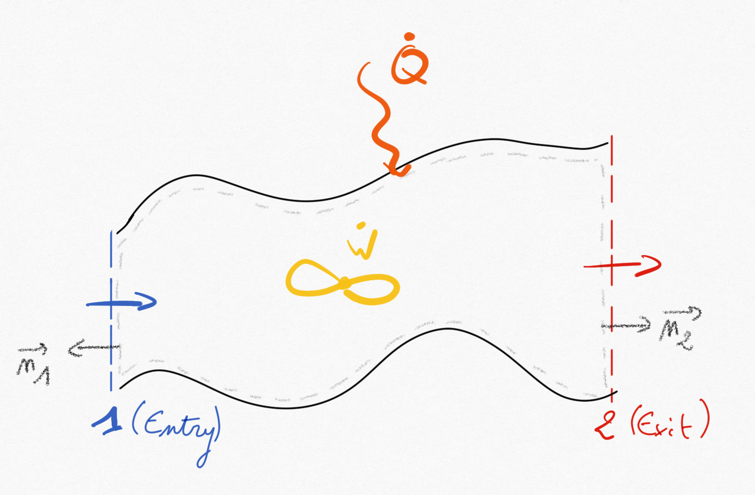
Figure 1.3: A fluid system with one entry and one exit
In that specific case, balance equations Eq.1.9 and Eq.1.10 simplify in:
(1.16)
and
(1.17)
1.2.1. Acceleration in a nozzle
Nozzles can be found in gas turbine or on aircrafts/rocket engines. They are basic components used to accelerate/decelerate a flow.
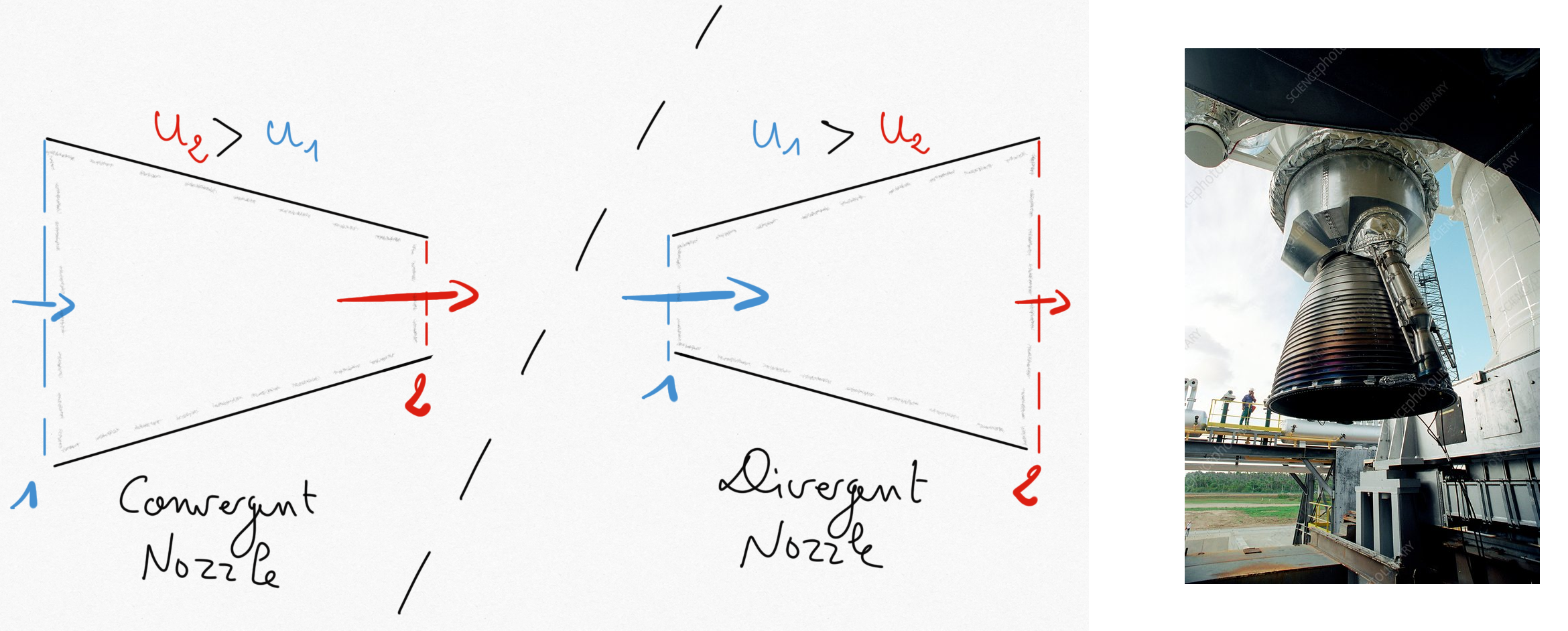
Figure 1.4: Left: subsonic convergent nozzle, Middle: subsonic divergent nozzle, Right: Ariane’5 Vulcain engine nozzle.
In nozzle systems:
It is commonly accepted that no thermal energy is exchanged (
) due to important fluid velocities.
Moreover, no working machine is present (
)
Potential energy is negligible.
such that relation Eq.1.17 becomes:
(1.18)
1.2.2. Heat exchanger
Heat exchangers allow to exchange a thermal energy between two fluids without mixing. The simpler heat exchanger is the double-tube presented in Figure 1.5: .
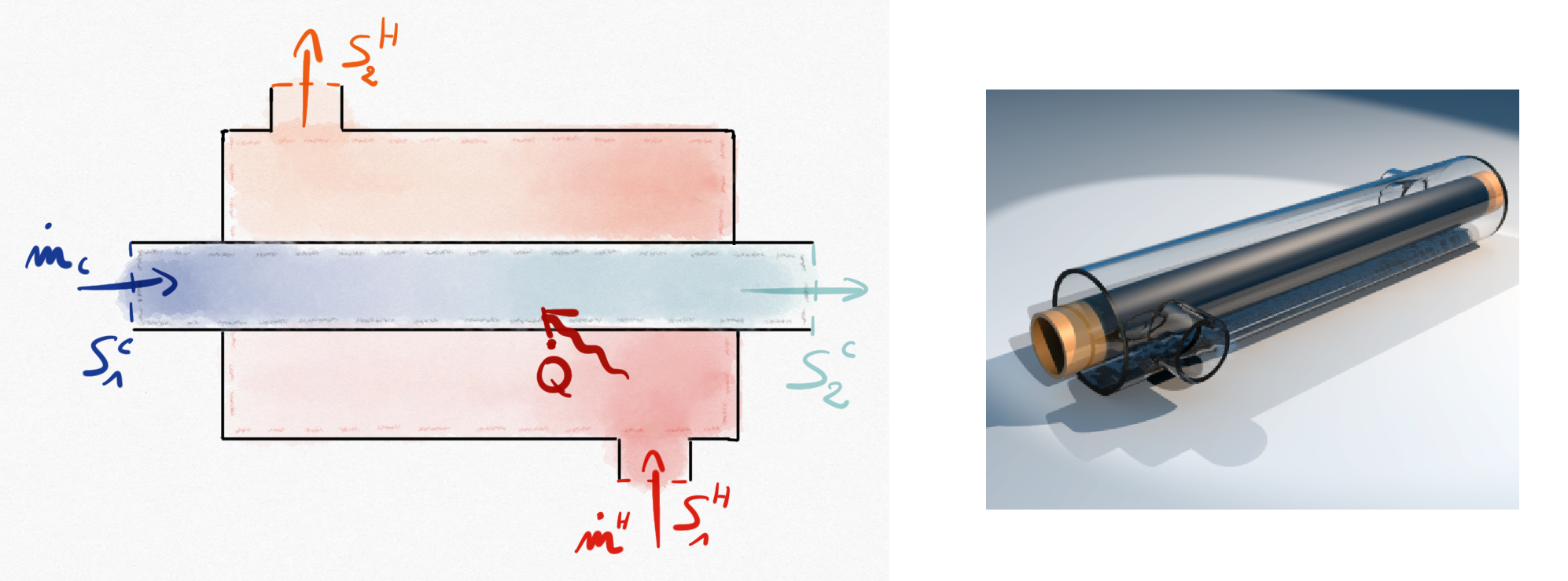
Figure 1.5: Double-tube heat exchanger. The cold fluid is absorbing thermal energy provided by the hot fluid.
In heat exchanger systems:
Kinetic energy variation is commonly negligible.
Potential energy is negligible.
No working machine is present (
)
Such that for example if considering the cold fluid system, the balance energy equation Eq.1.17 becomes:
(1.19)
If the heat exchanger is insulated, the hot fluid system balance energy will read:
1.2.3. Compressor/Turbine
These elements contains a rotary mechanical device to convert flow energy into mechanical work (turbine) and reversely (compressor). The mechanical work is transmitted thanks to a shaft.
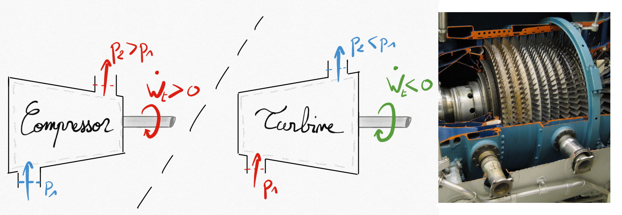
Figure 1.6: Left: schematic representation of a compressor and a turbine. Right: multi-stage compressor.
In these elements, this is commonly accepted that:
Kinetic energy variation is negligible.
Potential energy negligible.
No heat exchanges unless they are cooled (or heated)
.
Balance energy equation becomes:
(1.20)
In a turbine, a work is produced on the shaft ( because lost by the turbine), and the flow enthalpy is decreasing because of fluid expansion resulting in a lower pressure at the turbine exit than at the entry.
In a compressor, as for a pump or a ventilator, the fluid’s enthalpy is increasing because of fluid compression resulting in an increase of flow pressure as a work is provided on the shaft ( because earned by the compressor).
1.2.4. Throttling Valves
Throttling valves produce a pressure drop in a flow. It can be obtained thanks to adjustable valve or thanks to a porous.
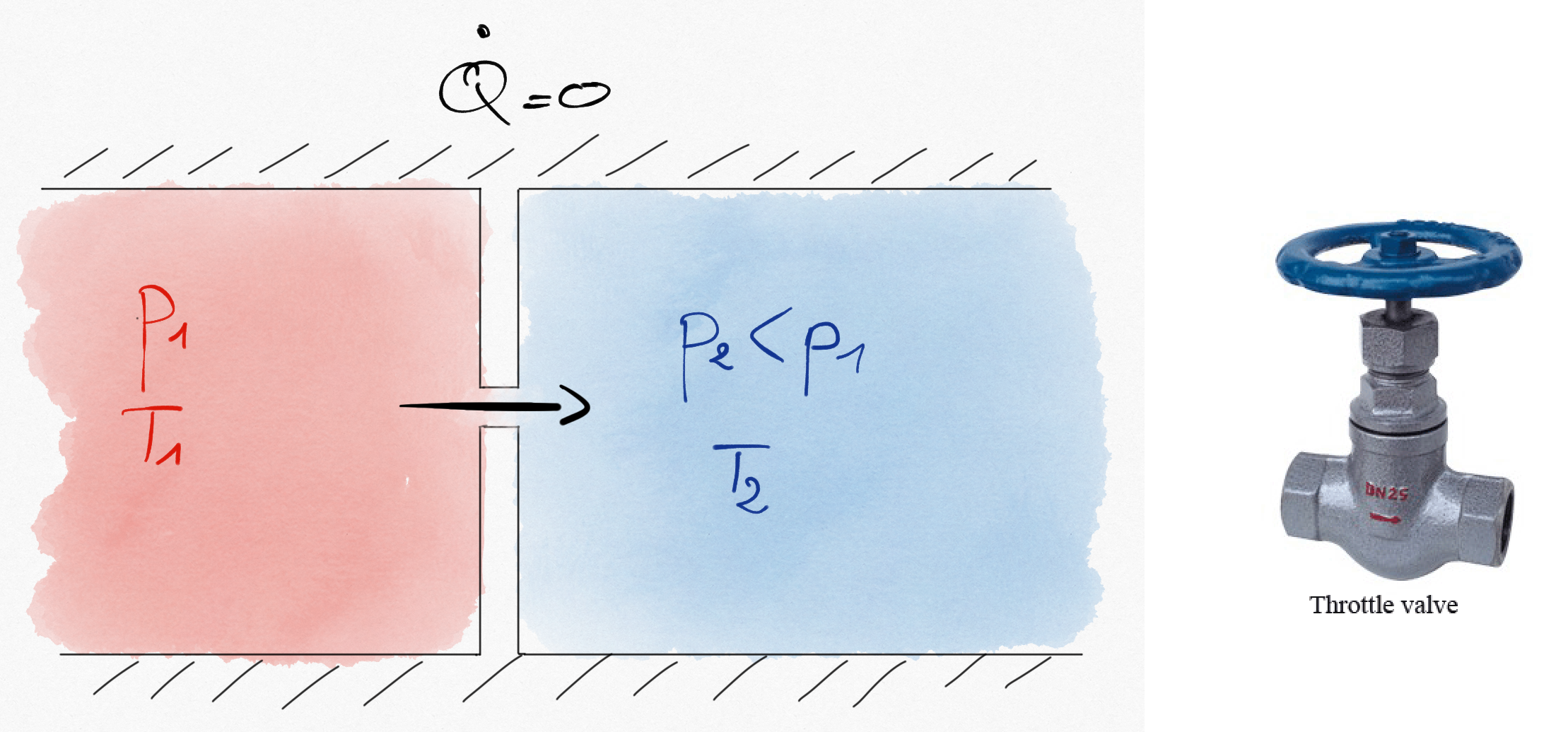
Figure 1.7: A high pressure gas is expanded through a hole. This kind of expansion is isenthalpic.
Common hypothesis are:
No heat echanges (insulated walls),
No working machine,
Kinetic energy variation is negligible.
Such that the first principle reduces to:
(1.21)
If the fluid can be considered as ideal gas, the isenthalpic expansion is also isothermal: