4.1. Reciprocating internal combustion engine
A reciprocating internal combustion engine (RICE) converts chemical energy of a fuel into mechanical work and thermal energy. We find two class of RICE:
Spark-ignition engines (SI) that use a spark to ignitate combustion of gasoline fuel.
Compression ignition engines (CI) that compress the mixture diesel fuel + air until the auto-ignition point.
4.1.1. Spark-ignition engines (SI RICE)
4.1.1.1. Overview
a SI RICE is composed with:
a combustion chamber where chemical reaction occurs,
a cylinder prolongating the combustion chamber,
a piston moving in the cylinder to vary the combustion chamber volume,
a connecting rod connecting the piston to the crankshaft. This system transforms the reciprocating movement of piston into a rotating one.
an intake valve and an exhaust valve to ensure fuel-air mixture intake and combustion gases exhaust.
a spark plug that generate a spark to ignitiate combustion.
The Figure 4.1: represents a schematic view of a SI RICE.
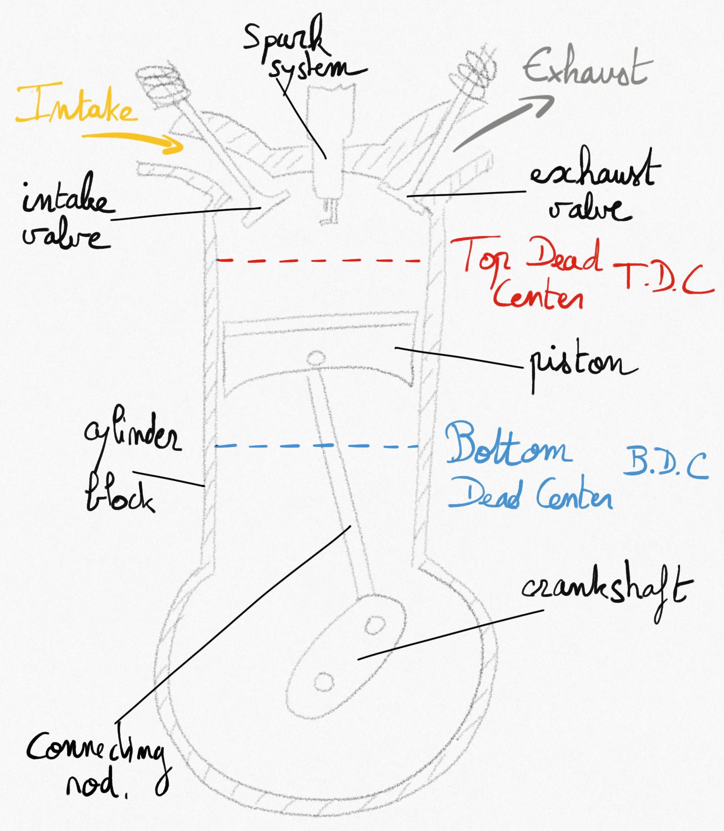
Figure 4.1: Schematic representation of a Spark-ignition engine.
The 4-stroke thermodynamic cycle occurs inside the combustion chamber as the piston is moving from top dead center (TDC) to bottom dead center (BDC) and reversely:
Intake stroke: the intake valve is open and the piston is moving from TDC to BDC allowing entry of fuel-air mixture (the charge) in the combustion chamber.
Compression stroke: both valves are closed as the piston is moving from BDC to TDC, ensuring compression of the mixture drawing work from the crankshaft. Just before the piston reach the TDC, the spark plug ignites the combustion.
Working stroke: Combustion is increasing temperature and pressure inside the combution chamber and the piston is pushed to BDC providing work on the crankshaft (more than in the compression stroke).
Exhaust stroke: the exhaust valve is open and the piston is moving from BDC to TDC pushing combustion gases outside of the combustion chamber.
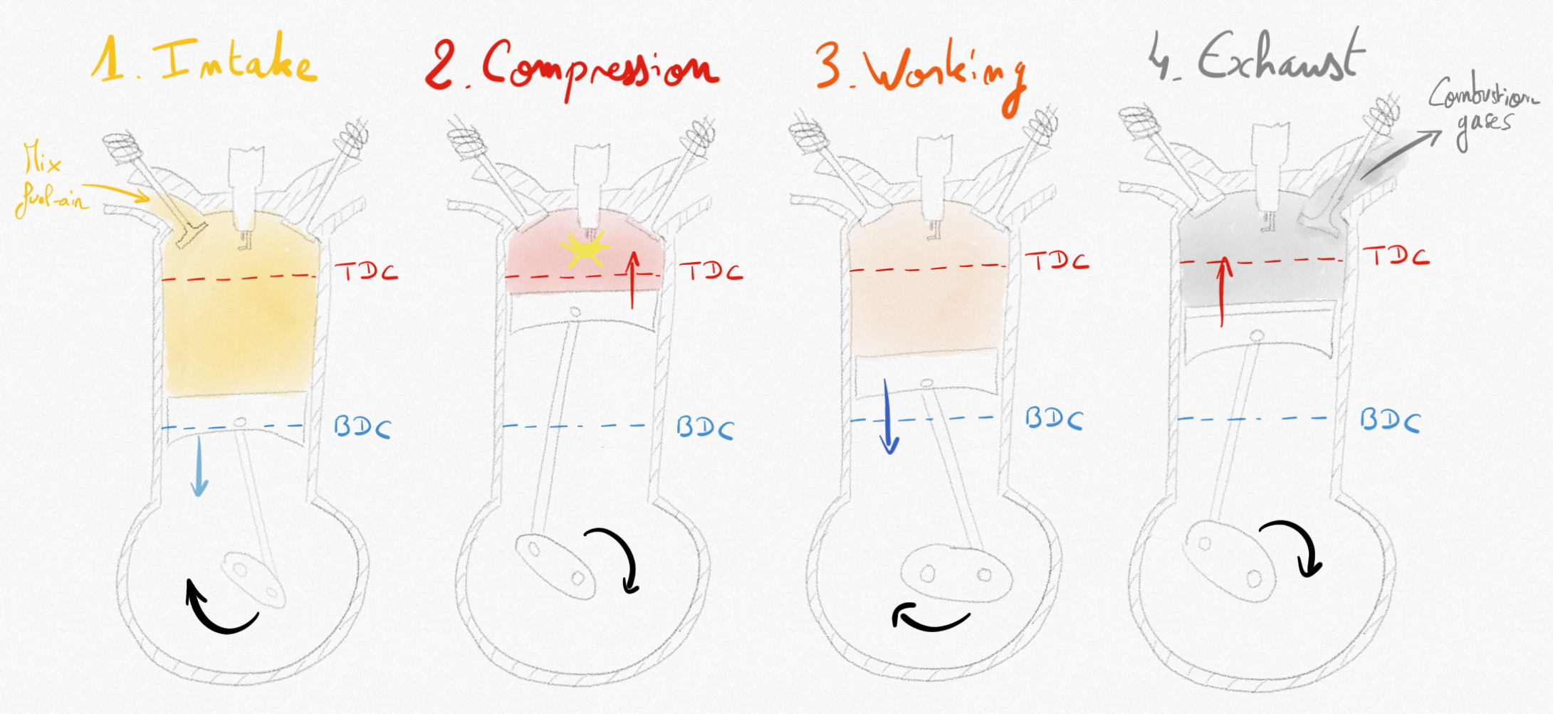
Figure 4.2: Schematic evolution in the SI RICE engine during the 4 strokes of the piston.
The 4 strokes of the piston constitute a complete thermodynamic cycle. It also corresponds to two complete rotations of the crankshaft.
4.1.1.2. Definitions
The compression ratio is defined as the ratio between the maximum cylinder volume and the minimum cylinder volume:
(4.1)
The displacement volume is the volume inside the cylinder displaced by the piston between BDC and TDC:
(4.2)
The mean effective pressure (PME) is the equivalent mean pressure acting along the piston stroke to obtain the real work.
(4.3)
remark
The PME is a practical value that permits to compare easily engines with the same displacement volume.
4.1.1.3. Beau de Rochas (Otto) cycle
French ingeneer Beau de Rochas proposed the SI RICE in 1862, and the German engineer Otto build it in 1876.
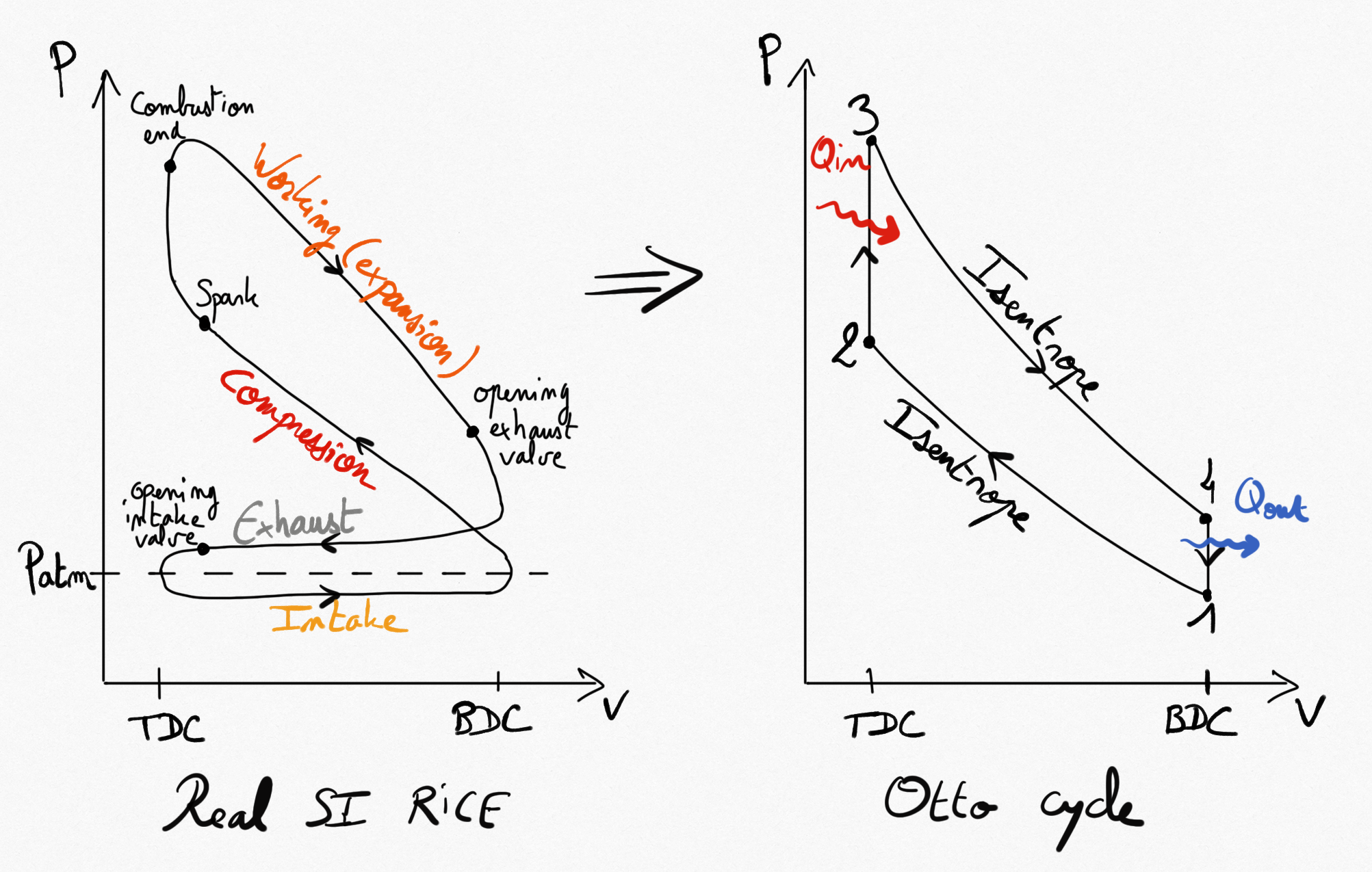
Figure 4.3: Real SI RICE compared to idealised Beau de Rochas cycle
Simplifications consist on considering 4 reversible transformations:
Compressions is isentropic.
Combustion is replaced by a constant volume heating.
Expansion is isentropic.
Heat exhausting is performed at constant volume.
As for any heat engine (Eq.2.9), the thermal efficiency of Beau de Rochas cycle is:
Considering the working fluid as an ideal gas, transformations 4-1 and 2-3 being at volume constant we obtain:
Because transformations 1-2 and 3-4 are isentropic and transformations 2-3 and 4-1 are isochore we can easily write:
and the thermal efficiency becomes:
(4.4)
Thermal efficiency for the Beau de Rochas cycle only depends on the compression ratio (Eq.4.1) and heat capacities ratio .
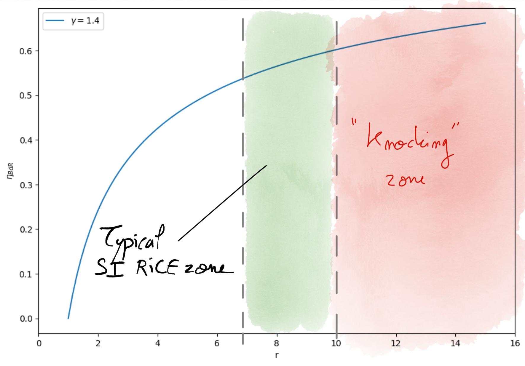
Figure 4.4: Beau de Rochas efficiency as a function of compression ratio in Gasoline engines.
The thermal efficiency rises with the compression ratio. Passed a value of , the combustion chamber size and the pressure and temperature increase may cause auto-ignition of the mixture in an uncontrolled maneer (before the Spark declenchement). This uncontrolled combustion generates shock waves in the combustion chamber leading to engine deterioration. This is known as engine knocking.
Typical zone of compression ratio for Gasoline engines are between 7 and 10 corresponding to maximum theoretical thermal efficiency of
. Real SI RICE engines thermal efficiencies do not exceed
.
4.1.2. Compression-ignition engine (CI RICE)
The fundamental difference with SI RICE is that only air penetrates during the intake stroke of the piston. Then during the compression stroke, air is compressed over the auto-ignition temperature. Diesel fuel is atomised from an injector directly in the combustion chamber and ignites spontaneously. This process reduces considerably engine knocking, allowing higher compression ratio, and consequentely better thermal efficiency.
4.1.2.1. Diesel cycle
In 1890, the German engineer Rudolf Diesel developped the first CI RICE. The theoretical idealised cycle corresponding to a CI RICE is the Diesel cycle.
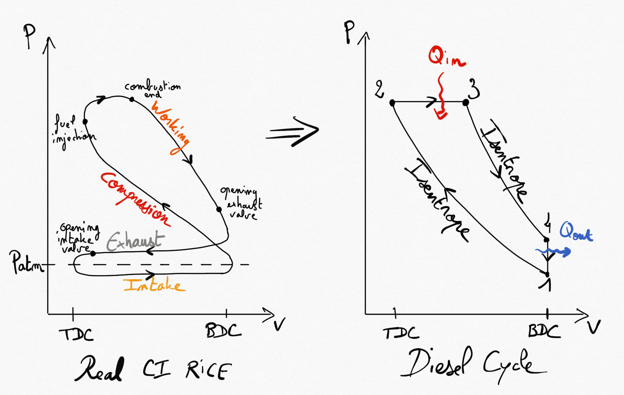
Figure 4.5: Real CI RICE compared to idealised Diesel cycle
Simplifications consist on considering 4 reversible transformations:
Compressions is isentropic.
Combustion is replaced by a constant pressure heating.
Expansion is isentropic.
Heat exhausting is performed at constant volume.
As for any heat engine (Eq.2.9), the thermal efficiency of Diesel cycle is:
Considering the working fluid as an ideal gas, transformation 4-1 being at constant volume and 2-3 being at constant pressure:
Because transformations 1-2 and 3-4 are isentropic we can write:
Then:
Because transformation 2-3 is isobare, we have
Finally, the thermal efficiency becomes:
(4.5)
The term in [] is greater than 1, such that we determine easily that for the same compression ratio, we have:
The equality occurs for
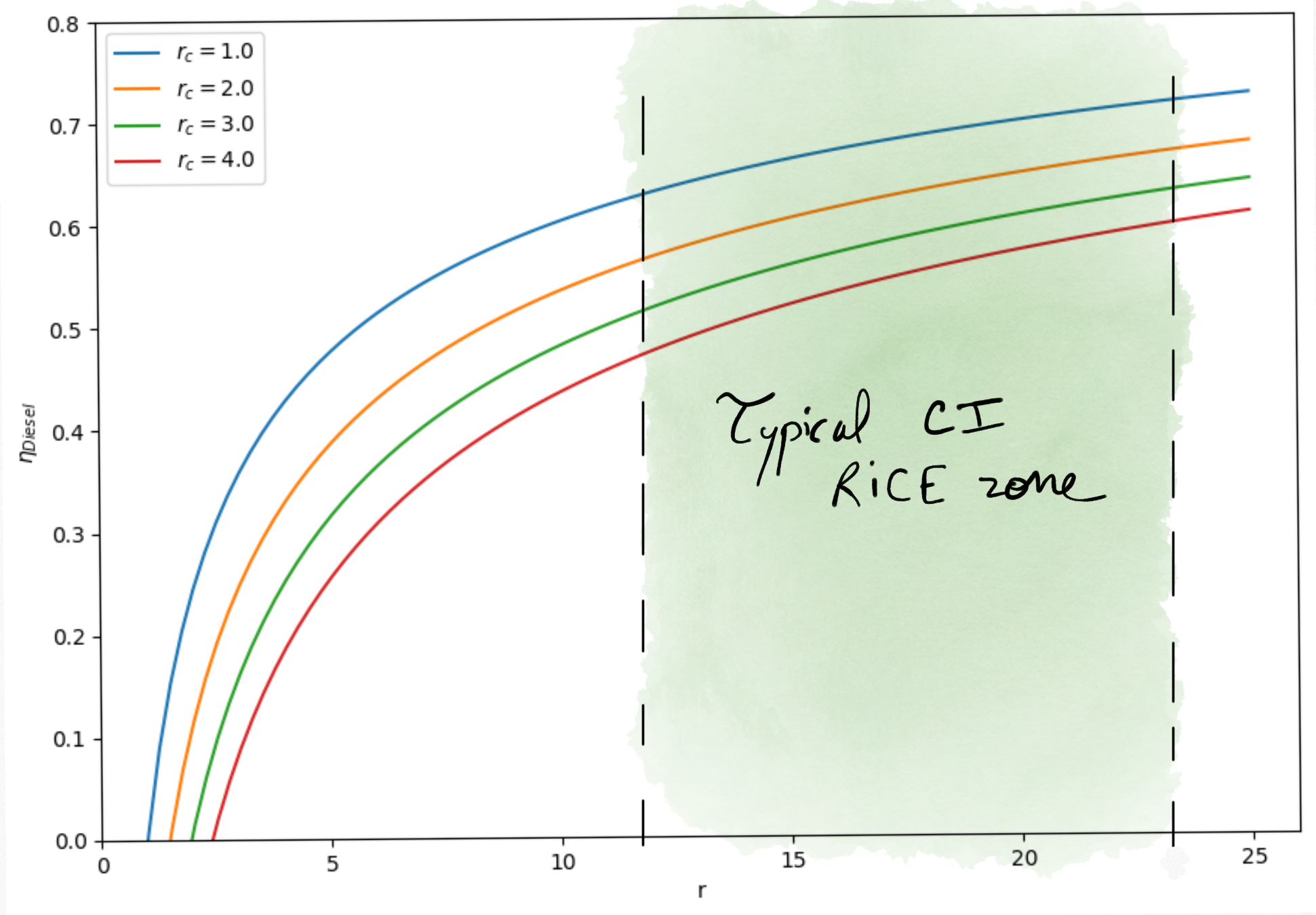
Figure 4.6: Diesel cycle thermal efficiency as a function of compression rate in Diesel engines (for different ).
Remark
For a same compression ratio, the thermal efficiency of Diesel engines is lower than for Gasoline engines. But, Gasoline engines accept a higher compression ratio.
As a result, Diesel engines real thermal efficiency may reach .
4.1.3. Turbocharger
A way to improve the power delivered by a RICE consists in increasing the quantity of air entering the combustion chamber during the intake stroke of the piston. This can be done by adding a compressor between atmosphere and the RICE. This compressor can be powered by the engine crankshaft directly. In that case we talk about supercharger. When the compressor is coupled to a turbine driven by exhaust gases, we talk about turbocharger.
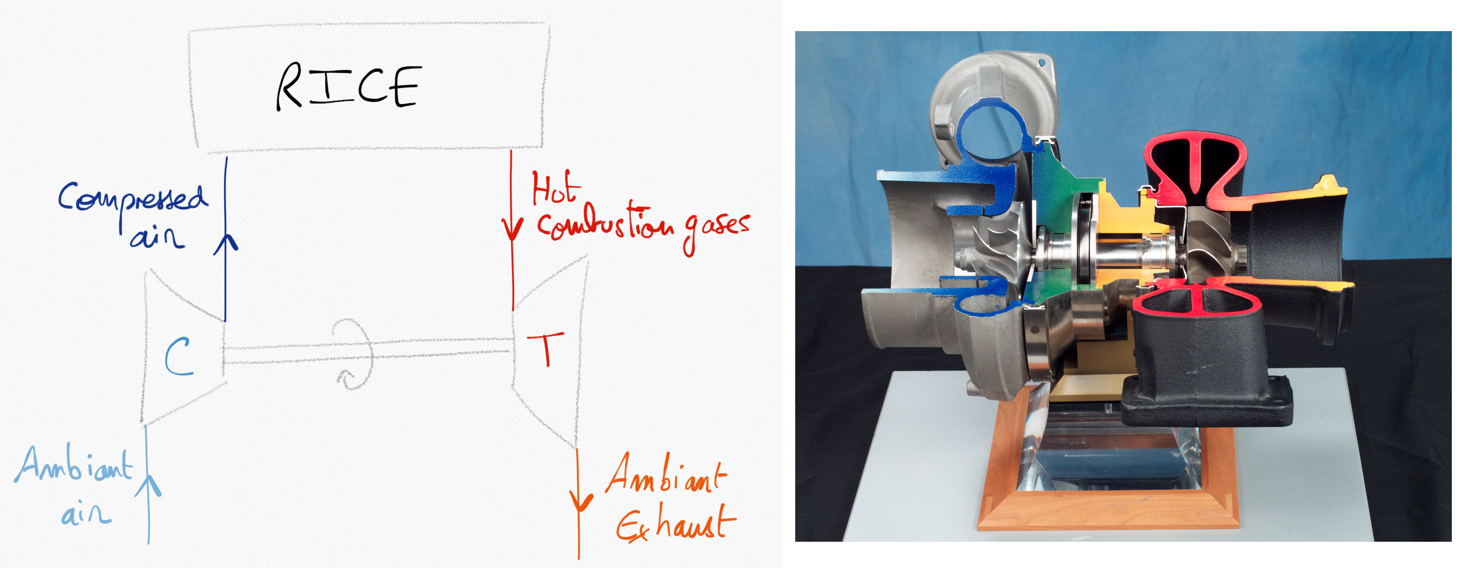
Figure 4.7: Turbocharger combining a compressor powered by a turbine. The turbine is driven by exhaust combustion gases.
The cycle of the heat engine is modified. For example, we present the turbocharged Diesel cycle.
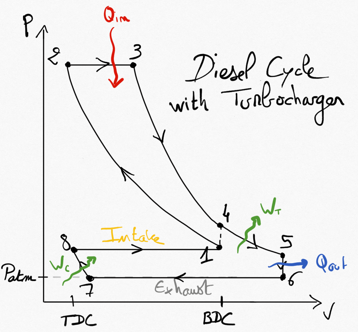
Figure 4.8: Idealized Diesel cycle using a turbocharger.