4.2. Gas Turbines
4.2.1. Overview
A Gas turbine is generally a continuous internal combustion engine (CICE) that transforms chemical energy of a combustion into mechanical energy, electrical energy or generate thust for propulsion. They are essentially used for transport (maritime or aeronautical) and electricity production. The simpler version of gas turbine is composed with:
A compressor bringing the atmospheric air to higher pressure and temperature.
A combustion chamber (or a heat exchanger) producing a high pressure and temperature gases.
A turbine sharing the same shaft as the compressor.
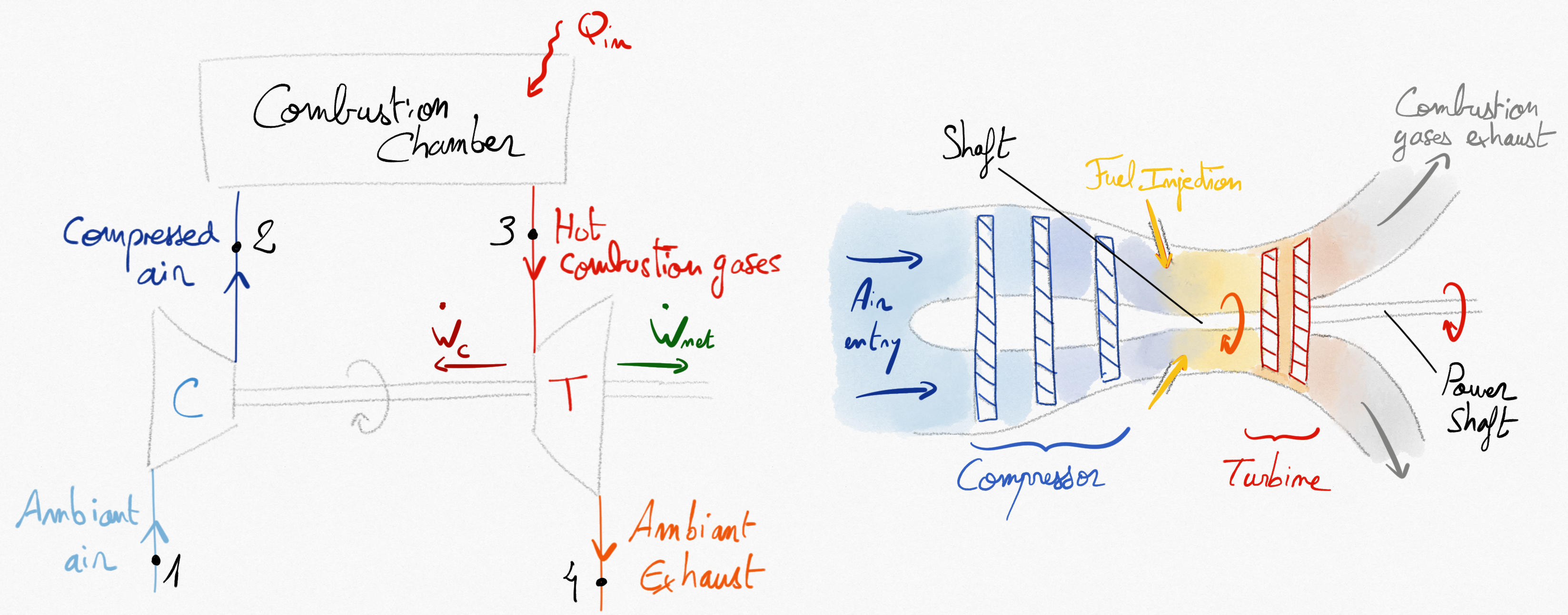
Figure 4.9: Simplified open cycle for a gas turbine
The turbine work is used to drive the compressor (). The remaining energy (not used for working fluid compresion) is then used in different maneer depending on the application:
It can be mechanically transmitted to a propeller for motion or to an electical generator. In that case, the net power available on the shaft is:
.
It can be used directelly as thrust in a turbojet engine. In that case, the net power on shaft is null.
4.2.1.1. Applications of gas turbine
Naval propulsion: The net power available on shaft is used to drive a ship’s propellers. This is the case for the MT30 gas turbine from Rolls Royce that equip the Queen Elisabeth and produces 40 MW or for turboprop of aircraft’s propellers.
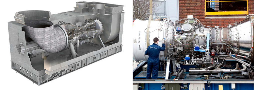
Figure 4.10: Gas turbine for naval propulsion.
Aeronautical propulsion: The net power of the turbojet engines is zero so that the turbine output only compensates for the power supplied to the compressor. In this case, the propulsion work is generated by the ejection of the burnt gases in the nozzle at the engine outlet which generates the thrust. The Rolls Royce Trent 900 engine powering the Airbus A380 is an example of this (300kN thrust).

Figure 4.11: Gas turbine for aeronautics.
Electicity production: These are the largest gas turbines and their colossal net power (over 400MW) is used to rotate the shaft of an alternator to produce electricity. The Siemens SGT5-8000H turbine generates 450MW of power.
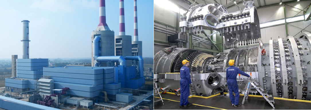
Figure 4.12: A thermal powerplant and the Siemens SGT-8000H turbine.
4.2.2. Brayton cycle
In 1870, the american engineer Georges Brayton build the first gas turbine. The ideal corresponding cycle is named Brayton cycle (or Joule cycle). This is a closed cycle.
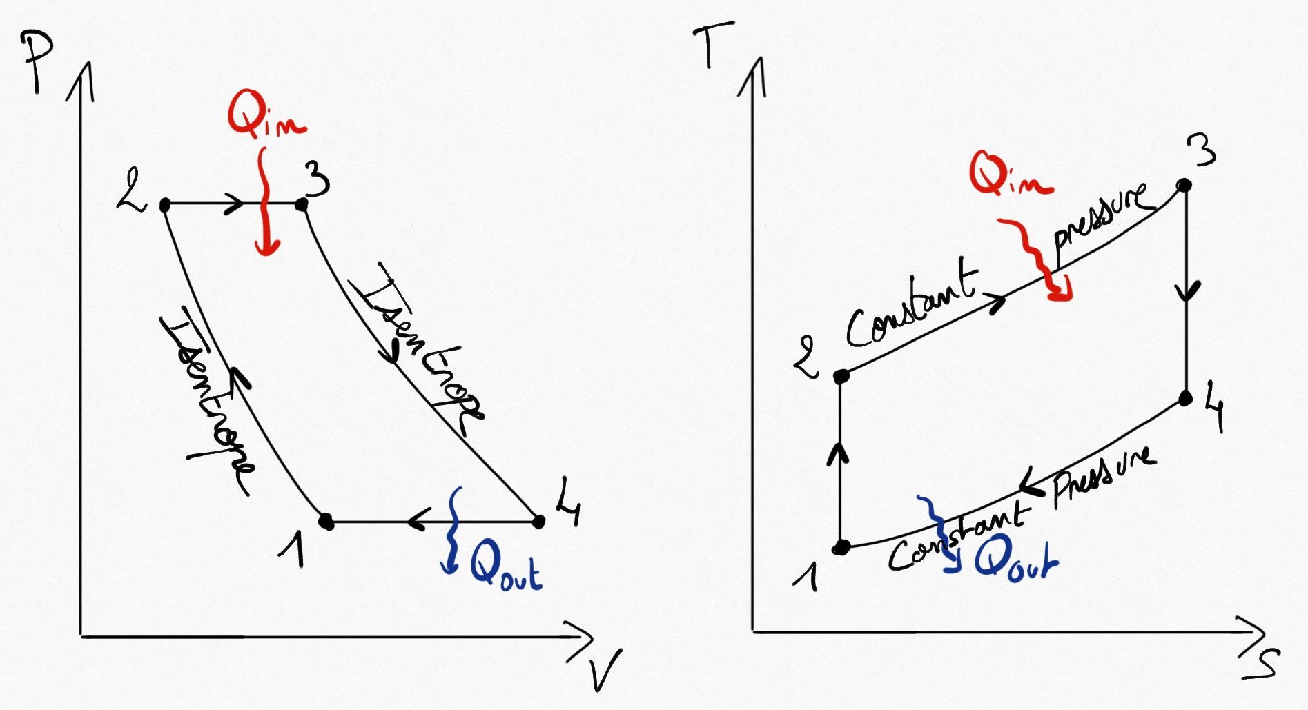
Figure 4.13: The Brayton cycle for ideal gas turbine.
Simplifications consist on considering 4 reversible transformations:
Compressions is isentropic.
Combustion is replaced by a constant pressure heating.
Expansion is isentropic.
The cycle is closed by a heat exhausting at constant pressure.
As for any heat engine (Eq.2.9), the thermal efficiency of Brayton cycle is:
Considering the working fluid as an ideal gas, and because no machine is working in transformations 2-3 and 4-1, application of the balance energy equation reads:
such that the thermal efficiency of Brayton cycle becomes:
It is possible to determine gas temperatures after the compressor and the turbine thanks to isentropic relations for ideal gases:
(4.6)
we finally obtain:
(4.7)
where is the pressure ratio of the gas turbine.
Remark
It is easy to show that the Brayton thermal efficiency is the same as the Beau de Rochas thermal efficiency (Eq.4.4).
Real gas turbine thermal efficienc rarely exceed 0.3.
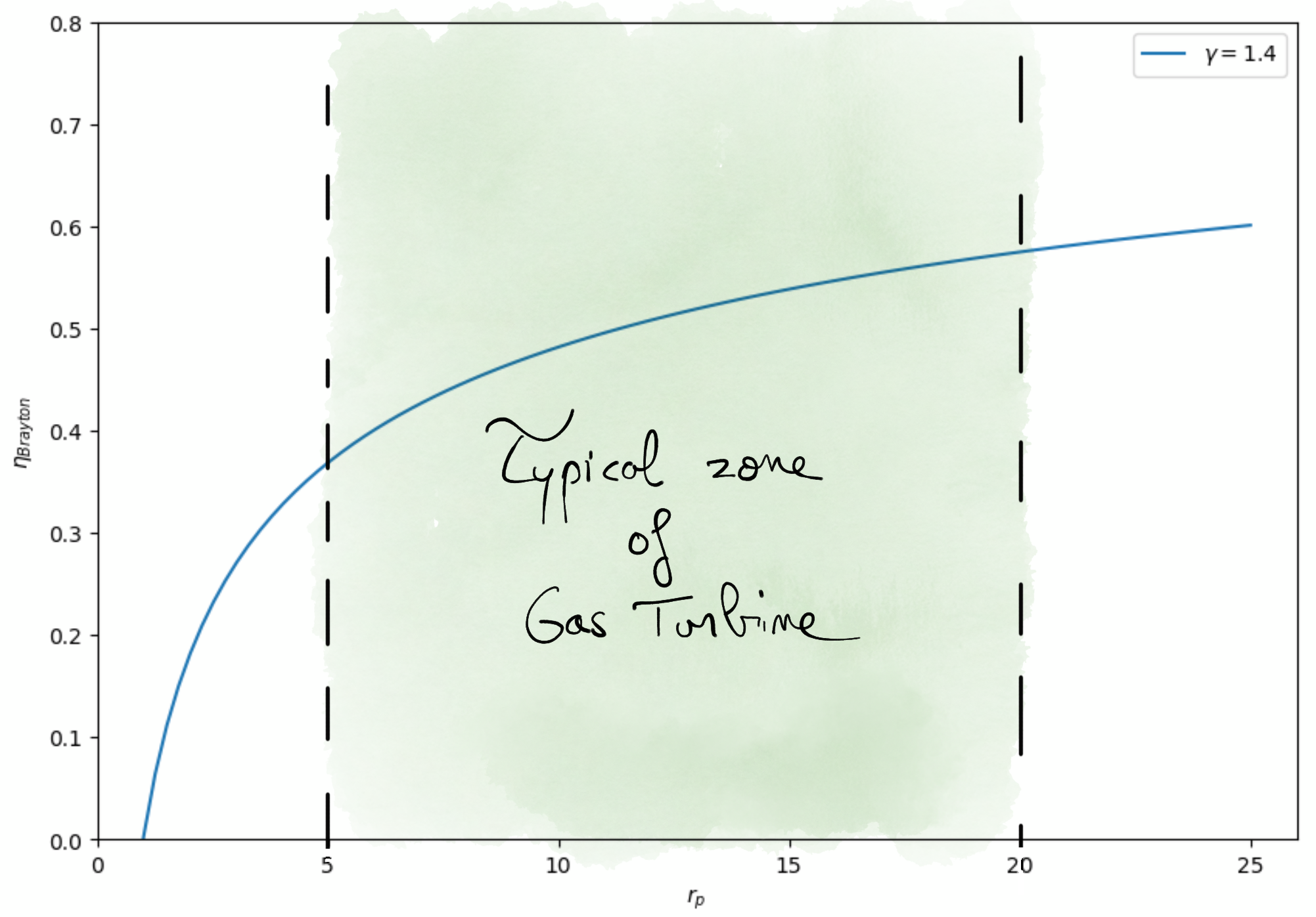
Figure 4.14: Brayton efficiency as a function of pressure ration.
4.2.3. Real gas turbine cycle
Real gas turbine cycle is different than those proposed by Brayton. This is due to non reversibility in the compressor and in the turbine and to the pressure drop in pipes.
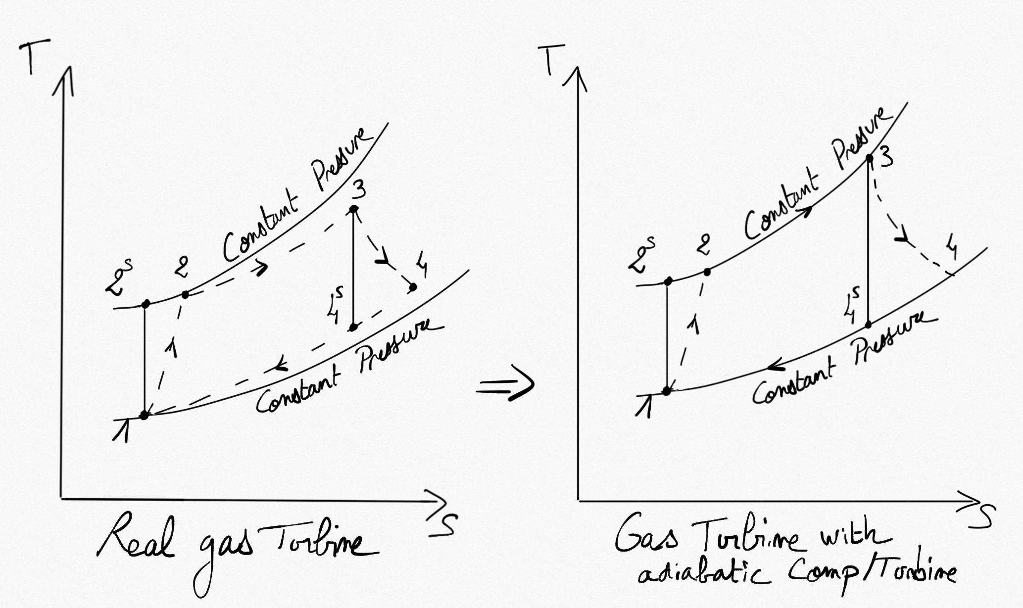
Figure 4.15: Gas turbine cycle with reversible/irreversible compression and expansion.
It is possible to easily account for the adiabatic compressor and adiabatic turbine irreversibilities by using the isentropic efficiency of both components (Real Compressions/Expansions). We have:
that becomes
(4.8)
Considering the working fluid as an ideal gas, we have:
(4.9)
Important
is the temperature at the turbine entry, chosen to be as big as possible, depending on the turbine blades resistance. Best turbines support a temperature of 1400 °C.
Relations Eq.4.9 permit the calcul of isentropic temperatures from a known pressure ratio.
Relations Eq.4.8 permit the calcul of real temperatures after compressor
and after turbine
from known isentropic efficiencies.
The global thermal efficiency of a gas turbine with adiabatic compressor and turbine is :
(4.10)
Figure 4.16: shows the impact of irreversibilities in adiabatic compressor and turbine on the thermal efficiency of the real gas turbine.
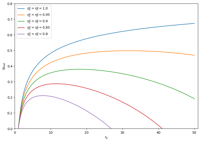
Figure 4.16: Thermal efficiency of a real gas turbine. 
4.2.4. Regeneration
An important part of energy is lost with hot exhaust gases. Because the temperature of gases exiting the turbine () is higher than those exiting the compressor (
), a heat exchanger can be used to save a part of the combustion energy. It is named: regenerator.
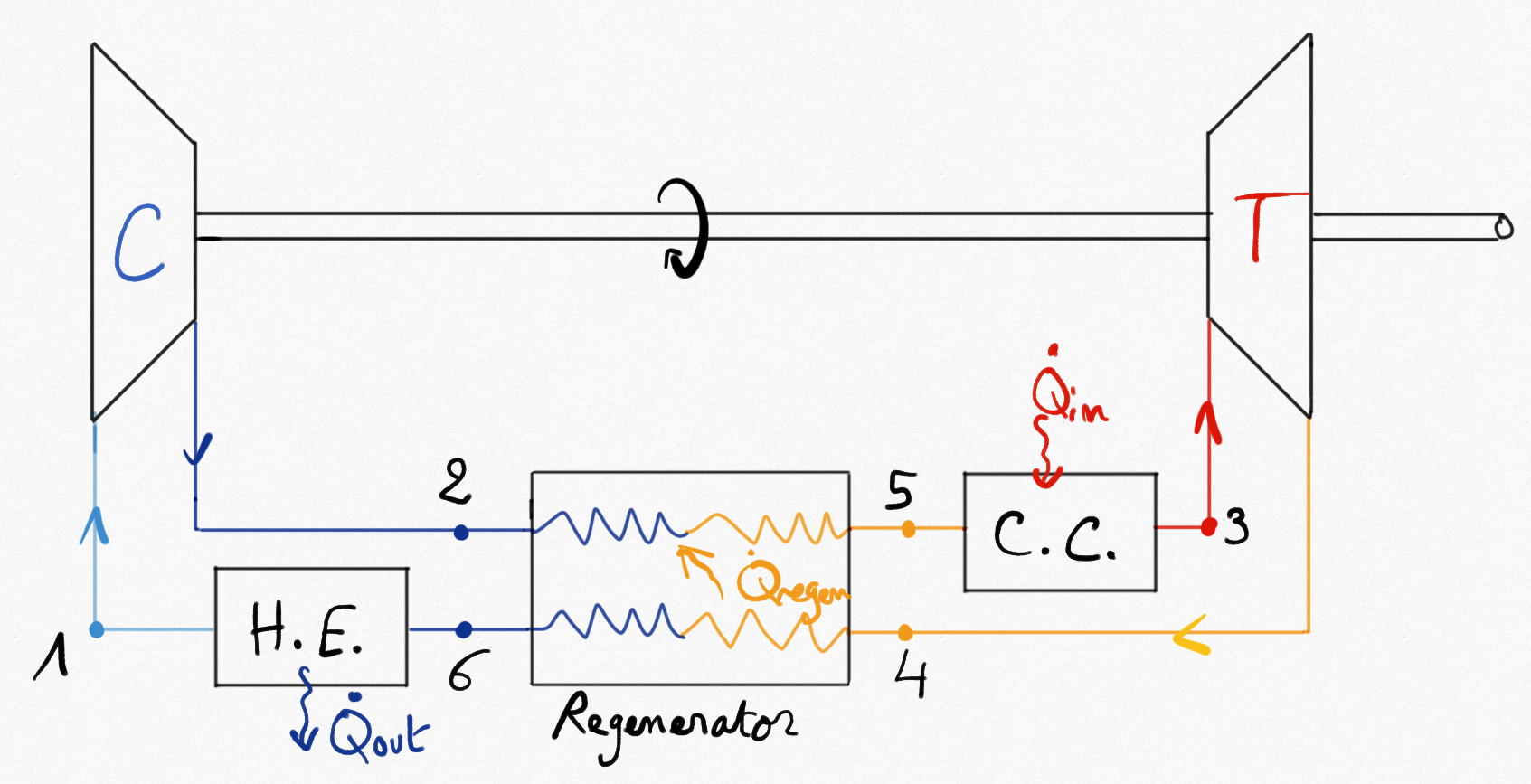
Figure 4.17: Gas turbine equipped with a regenerator improving thermal efficiency.
In the regenerator we suppose that kinetic energy variation are negligible. Moreover, the regenerator is supposed to be adiabatic. The modified Brayton cycle becomes:
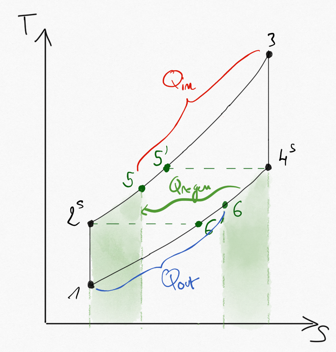
Figure 4.18: Ideal Brayton cycle with regenerator (isentropic in compressor, turbine).
4.2.4.1. Regenerator effectiveness
Considering the heat exchanger as ideal, the working fluid is entering in the combustion chamber with the same temperature as exhaust gases
such that the maximum heat flux saved using a regenerator is:
The real heat flux saved is:
We defined the regenerator effectiveness as:
Under ideal gases assumption, the regenerator effectivness becomes:
(4.11)
Typical value of are lower than
.
4.2.4.2. Thermal efficiency
The thermal efficiency of Brayton cycle with regeneration is:
Considering the working fluid as an ideal gas, and because no machine is working in transformations 5-3 and 6-1, application of the balance energy equation reads:
such that the thermal efficiency of Brayton cycle with regeneration becomes:
It is possible to determine gas temperatures and
using the regenerator effectiveness:
The thermal efficiency becomes:
For ideal adiabatic compression and expansion, isentropic relations Eq.4.6 can be used and the thermal efficiency of Brayton cycle with regeneration finally becomes:
(4.12)
where is the pressure ratio of the gas turbine.
In the limit case of ideal regenerator (), the thermal efficiency becomes:
(4.13)
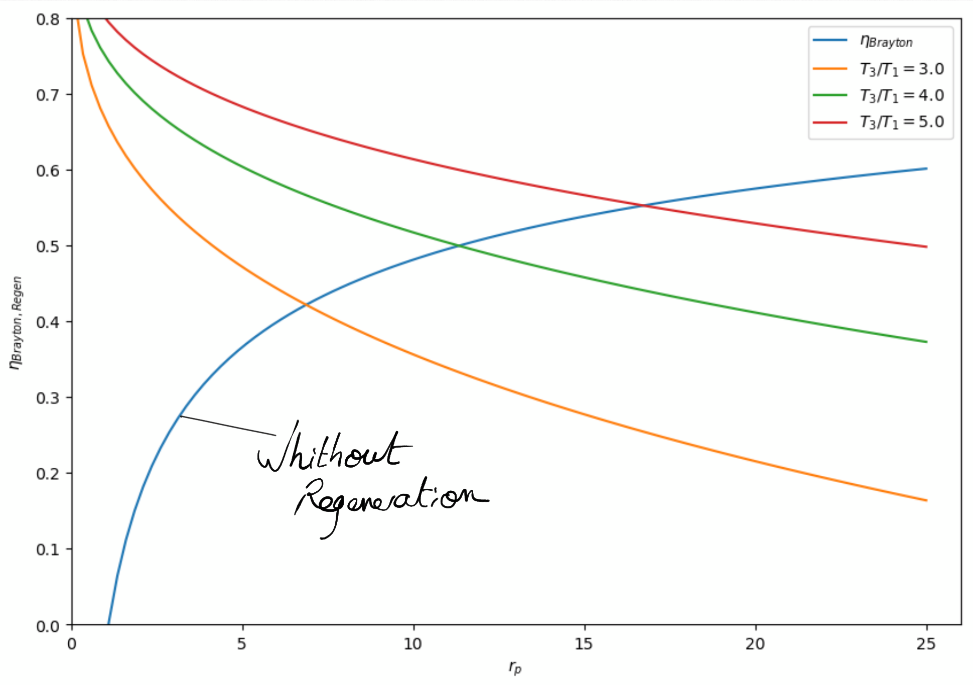
Figure 4.19: Ideal Brayton cycle with regenerator thermal efficiency (isentropic in compressor, turbine). The thermal efficiency is better with regenerator for low pressure ratio.
Remark
When adiabatic compression (compressor) and expansion (turbine) are not reversible, thermal efficiency of the cycle can be obtain using definition of isentropic efficiencies (Eq.4.8)
4.2.5. Intercooling and reheat
As shown in Section 3.2: , we can optimize compression by using multi-stage compression with intercooling and optimize expansion using multi-stage expansion with reheat.
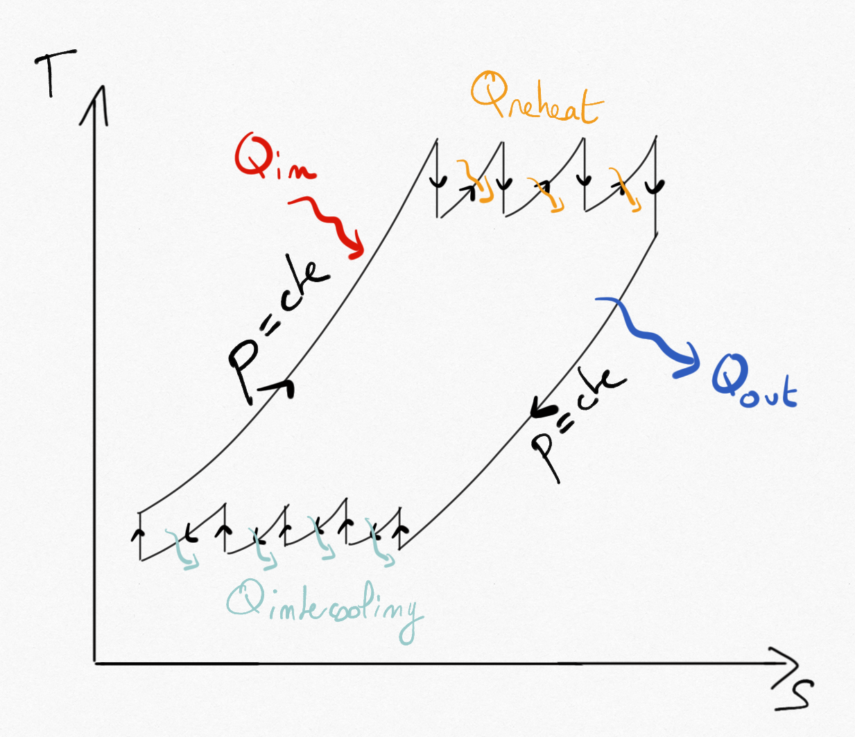
Figure 4.20: Brayton cycle using multi-stage compression with intercooling and multi-stage expansion with reheat.
As the number of reversible compressions and expansions stages increase, the two isobares are linked to two isotherms and the thermal efficiency becomes equal to Carnot’s thermal efficiency.
Practically, two or three stages are used for both compression/expansion. Intercooling is often ensured by external air. Because comburant (air) is in excess during combustion, reheat can be ensured by injecting fuel between expansion stages.
4.2.6. Turbojets
In turbojets, the technical work provided from the turbine is used to compensate the power supplied to the compressor. Then, burnt gases are exhausted at a pressure greater than the atmospheric pressure. They can be expanded in a nozzle to produce a thrust.
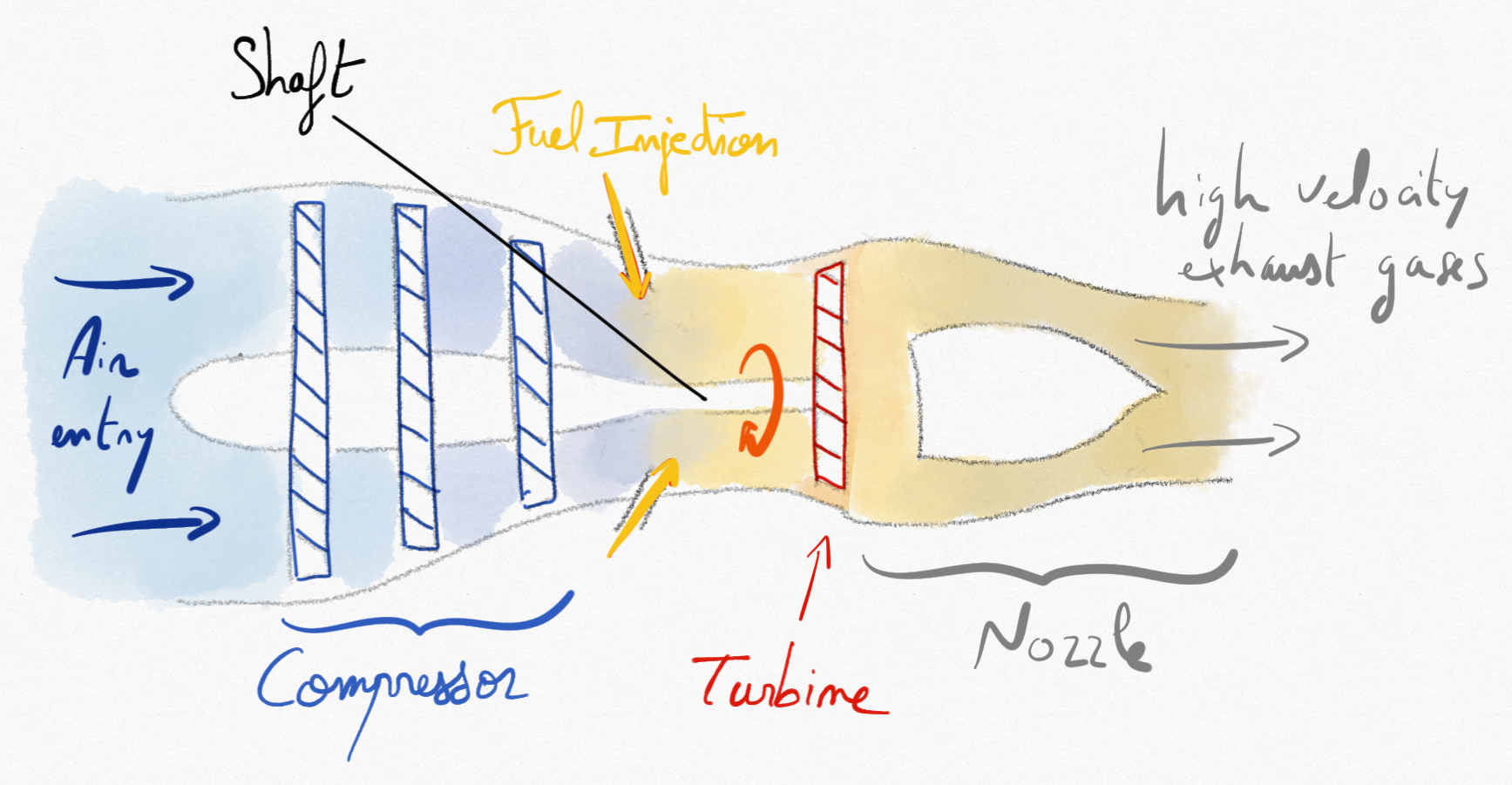
Figure 4.21: Schematic representation of a simple turbojet.
The thrust provided by the turbojet can be determine by momentum balance:
(4.14)