We would like to thank our sponsors for making this project possible:
## 📁 TABLE OF CONTENTS
* [1. 👥 The Team ](#1--the-team)
* [2. 🤖 Our Robot](#2--our-robot)
* [3. 📝 Daily documentation](#3--daily-documentation)
* [4. 🛠️ Mechanical Design](#seccion-mecanica)
* [5. 🪛 Mobility design](#5--mobility-design)
* [6. ⚡Power and Sensor Architecture](#6--power-and-sensor-architecture)
* [7. 🧠 Strategy](#7--strategy)
* [8. 💻 Software](#8--software)
* [9. 🦾 Build our robot](#9--build-our-robot)
### 1. 👥 The Team
The Minaguro team from Herencia, Spain, is made up of dedicated and hardworking members led by a teacher. This is our first year competing in the WRO Future Engineers category, and each member brings important skills to the team.
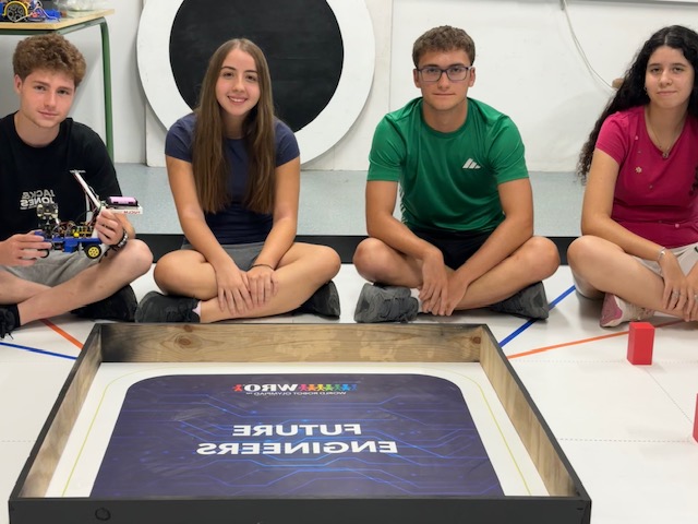 team photo |
 funny team photo |
**Miguel**
**Age:** 17
**Description:** Hi, I'm Miguel from Ciudad Real, Spain, and this is my first time participating in WRO Competition. I have always been into mechanics and robot building, so I didn't hesistate to take up this challenge. I am such a curious and competitive person, and I had put all my efforts in helping the team.
**Natalia**
**Age:** 17
**Description:** Hi, I am Natalia, also from Ciudad Real, Spain, and it is my first time participating, too. I am really good at programming, which I actually enjoy doing. I am hardworking and creative, and this competition, despite being really demanding, has helped me to enter the engineering world.
**Rocío**
**Age:** 16
**Description:** Hi! I'm Rocío from Spain and this is the first time in the WRO competition. Since I was a kid, I've loved solving puzzles and maths problems. I started to interest in robotics when I was at secondary school, when my teacher taught us how to program. I thougth that was really fun.
**Guillermo**
**Age:** 16
**Description:** Hi, I am Guillermo. I am from Ciudad Real, Spain, and I joined this project because I have always been really keen on I.T. and problem solving. Although this competition has been really challenging, the experience with all the team is worth it.
### 2. 🤖 Our Robot
#### 2.1 First Version (Arduino)
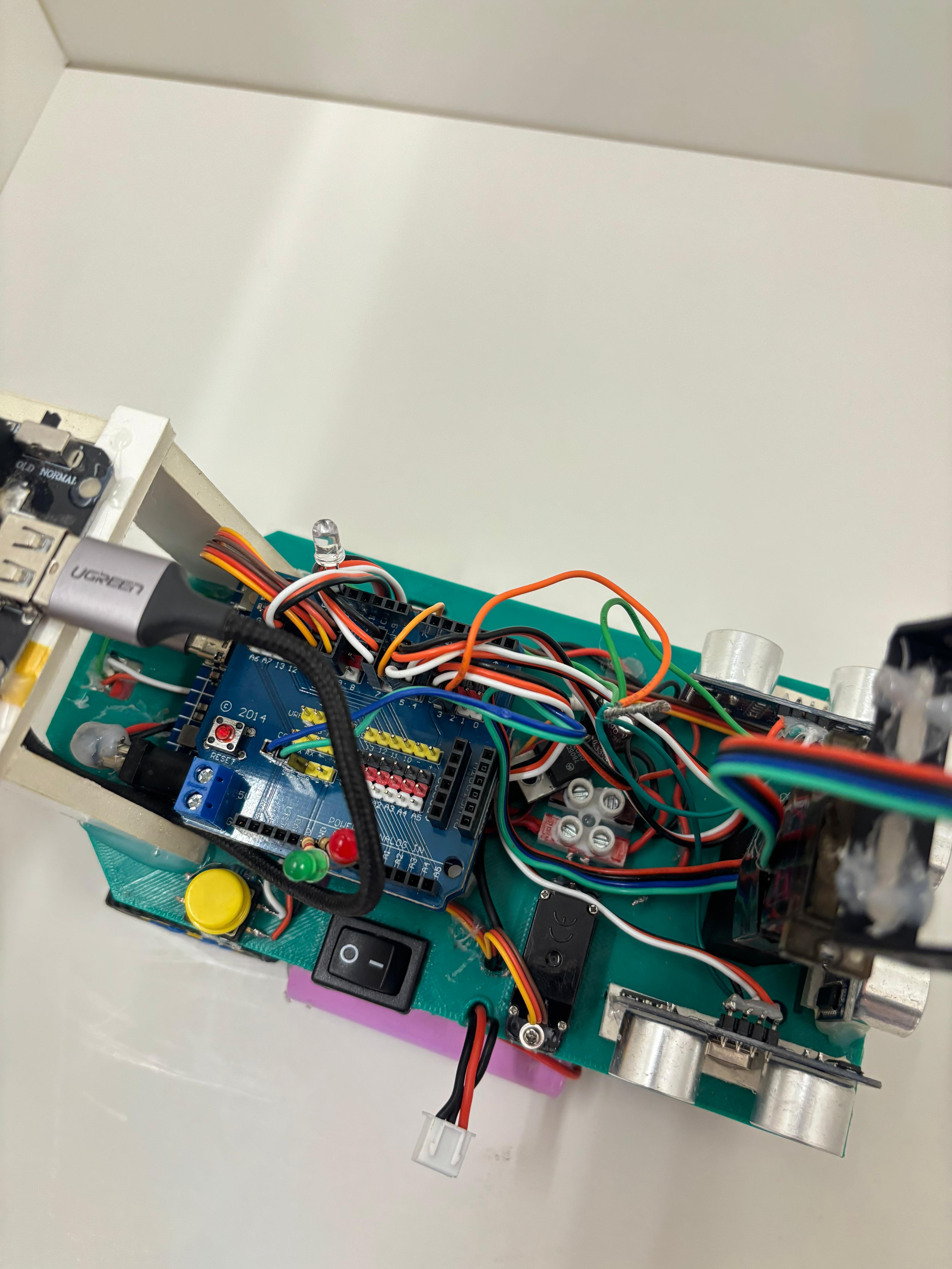
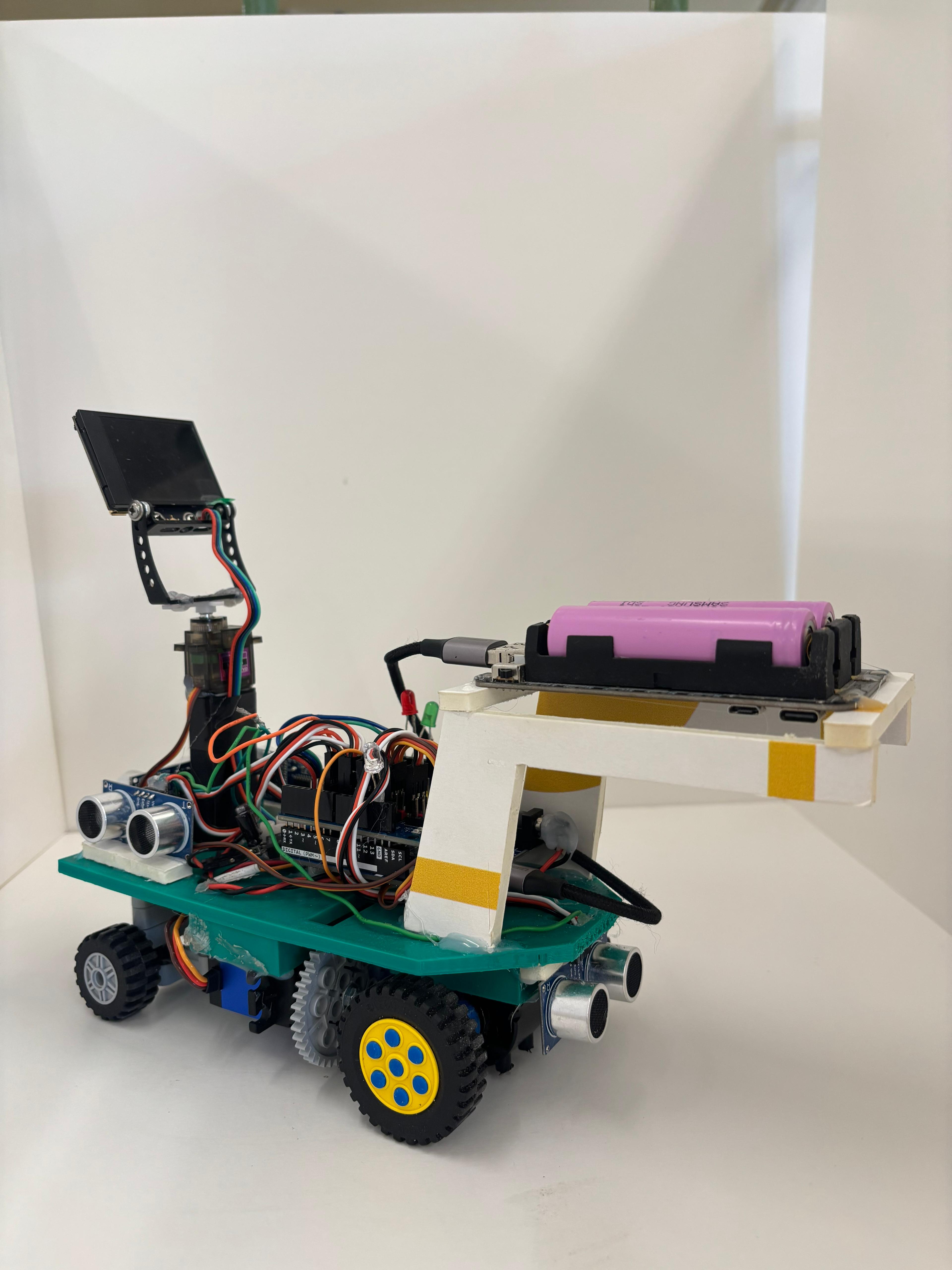
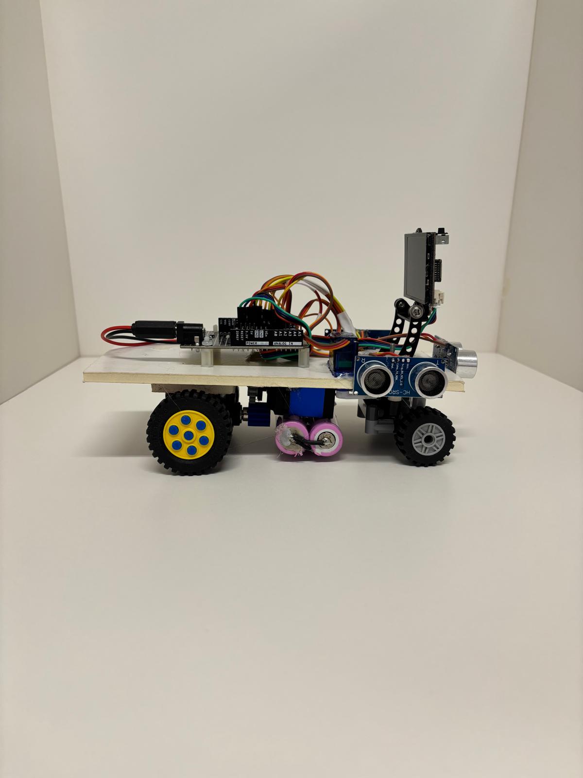
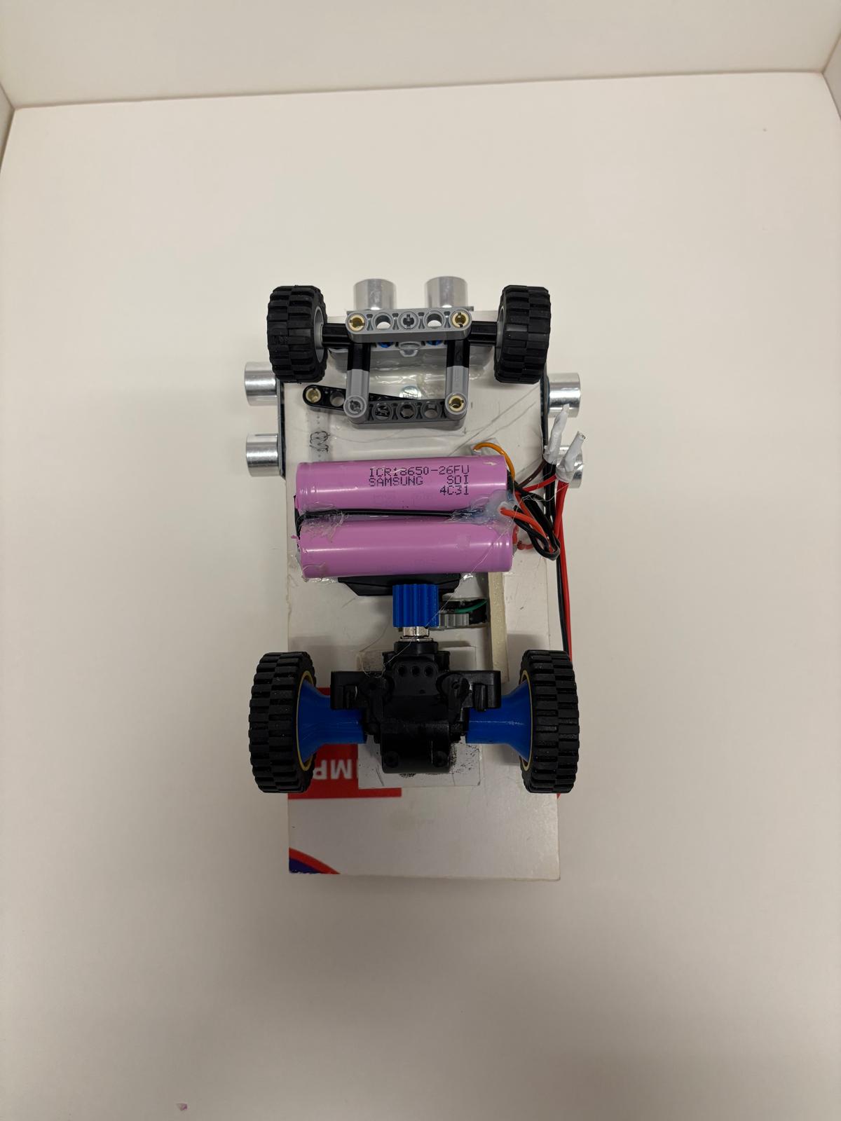
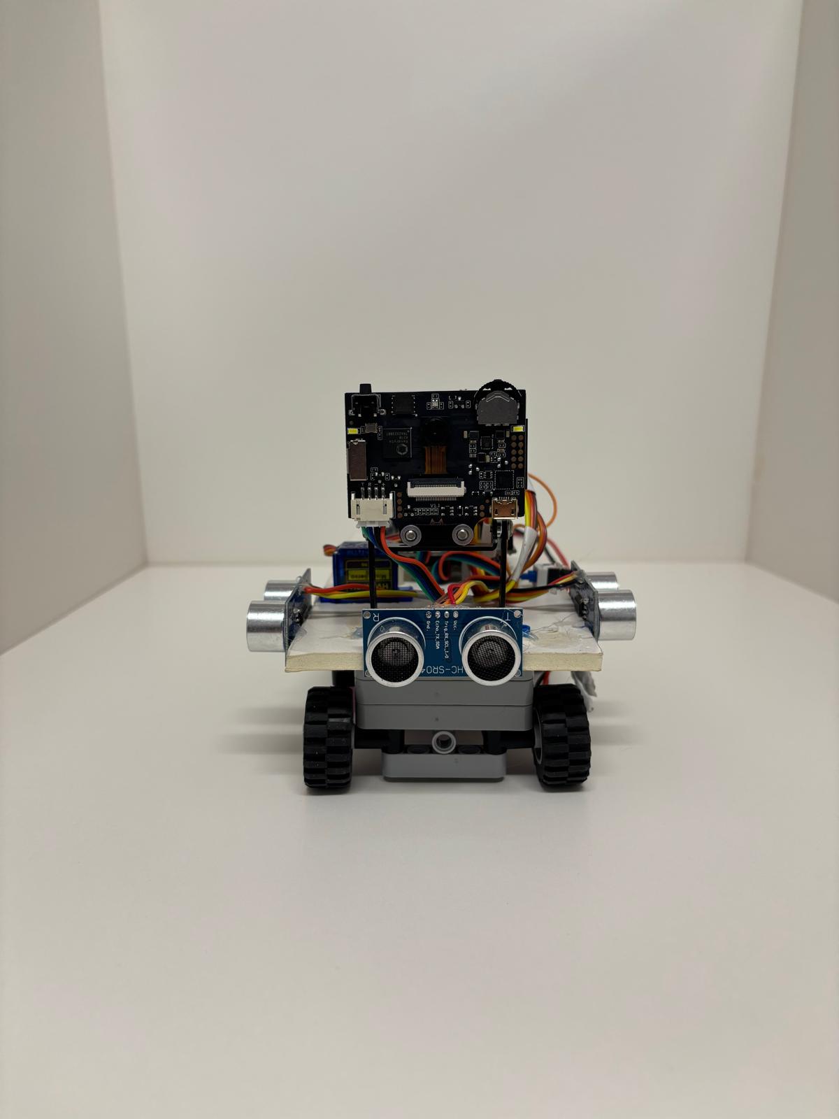
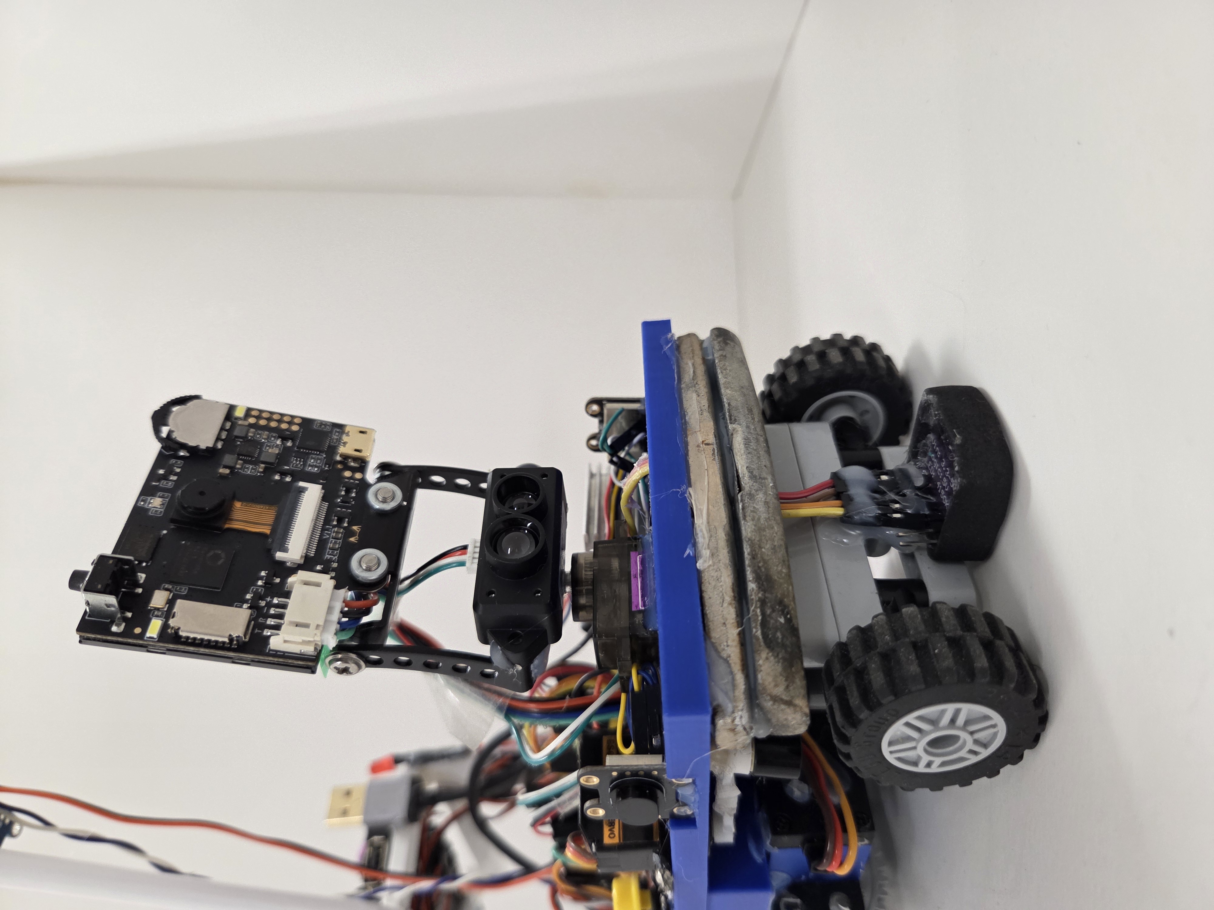
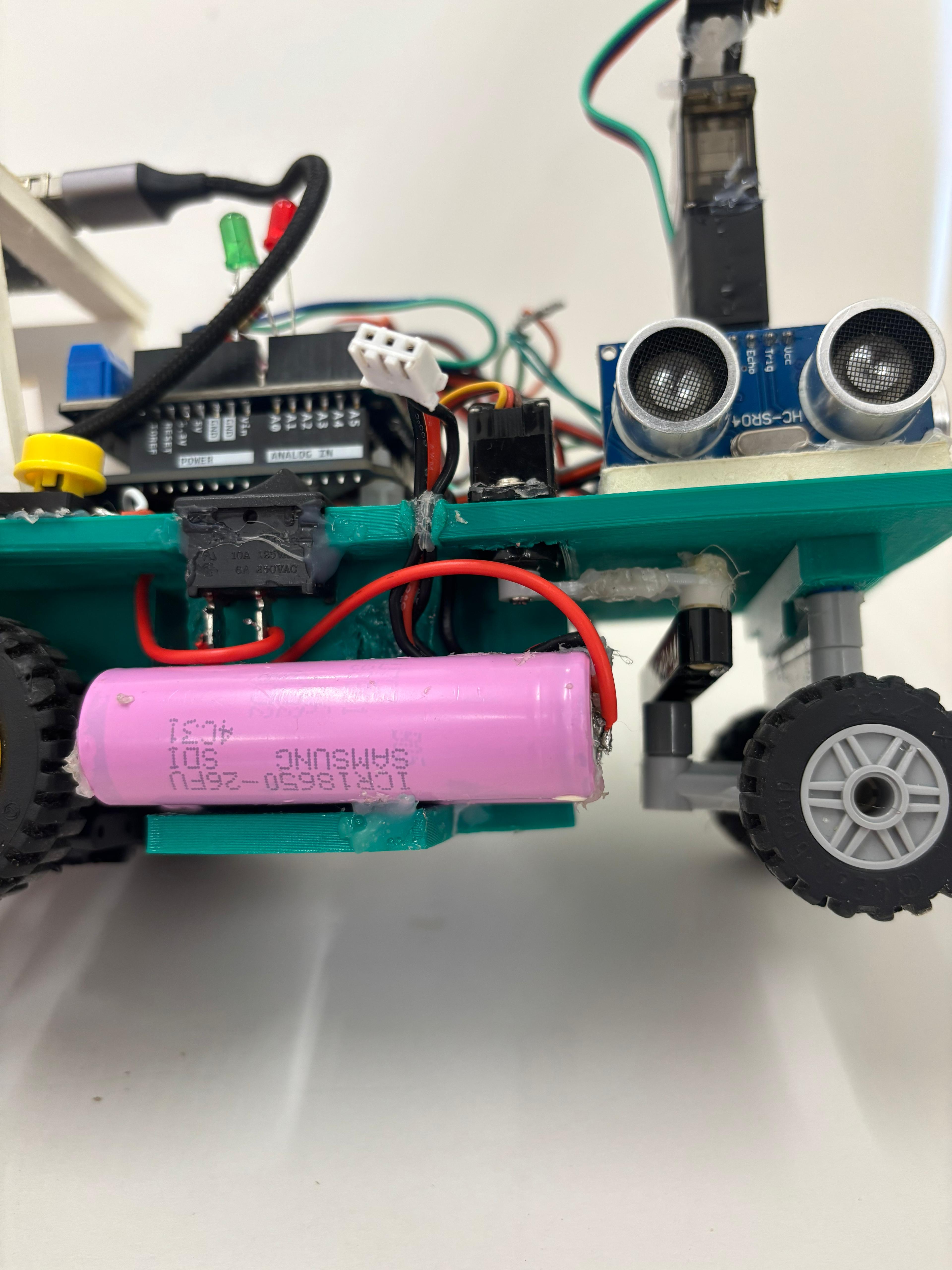
Here are some pictures of our robots first version to help with it´s reproducibility:
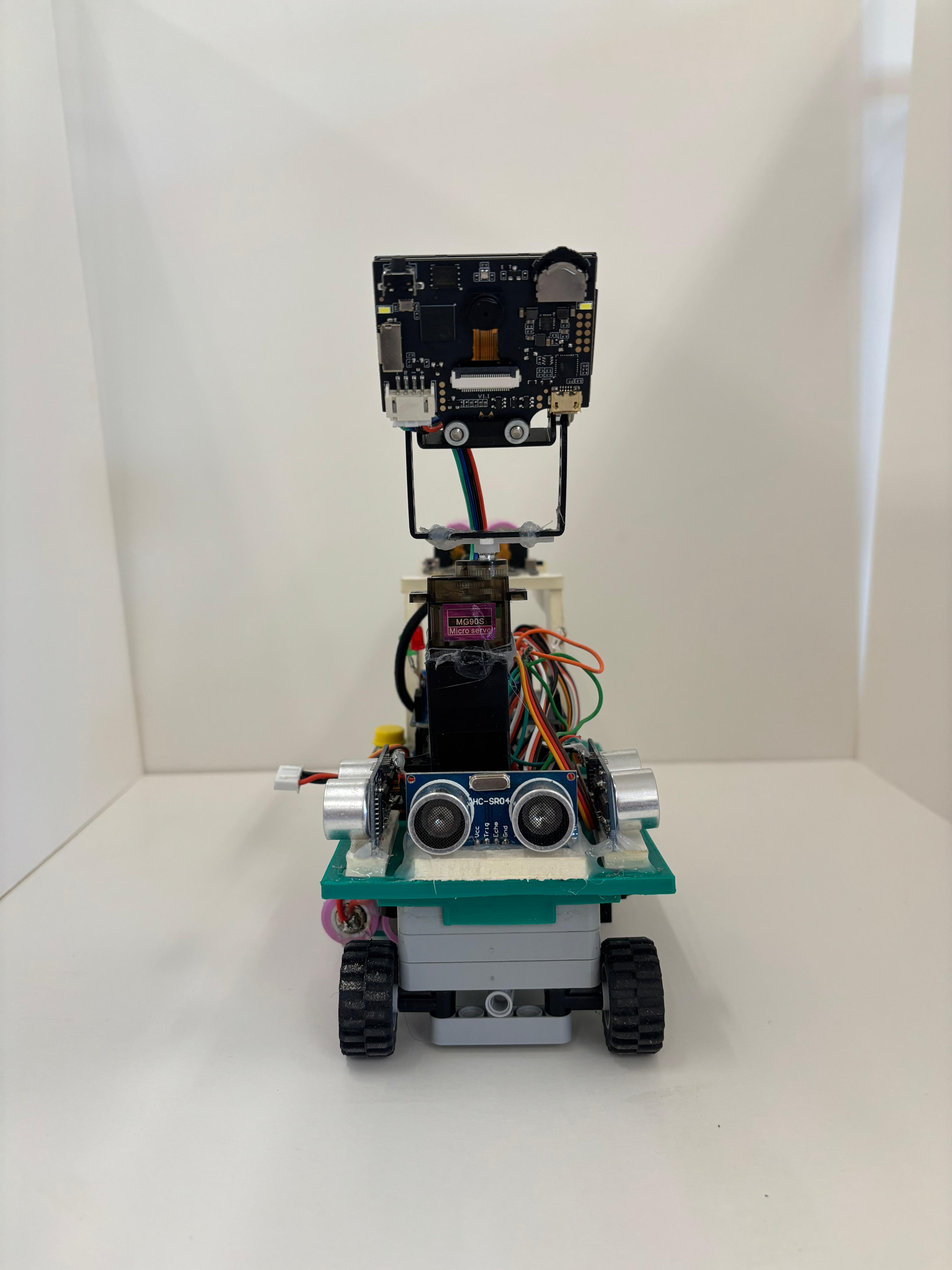 robot´s front view |
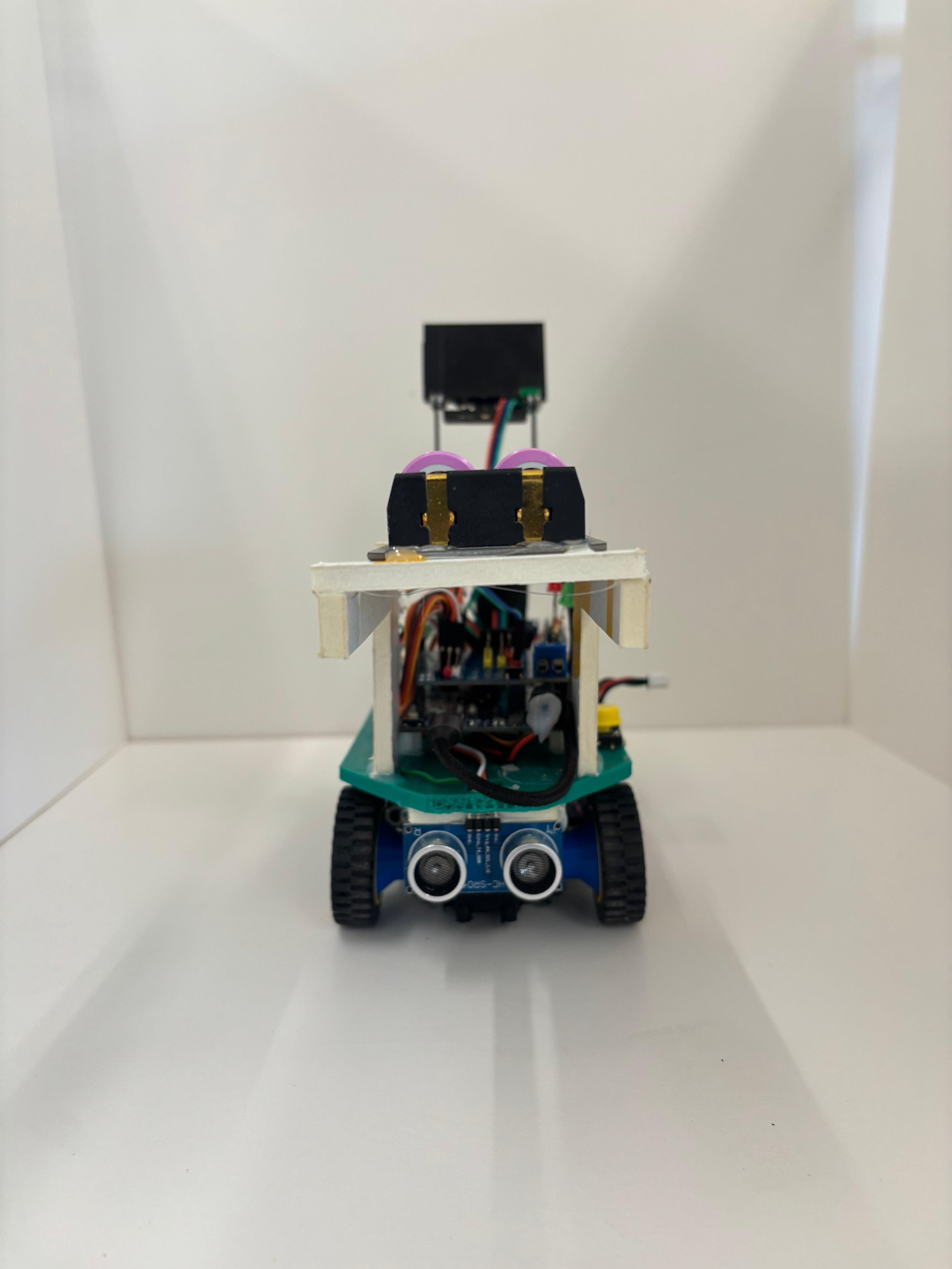 robot´s back view |
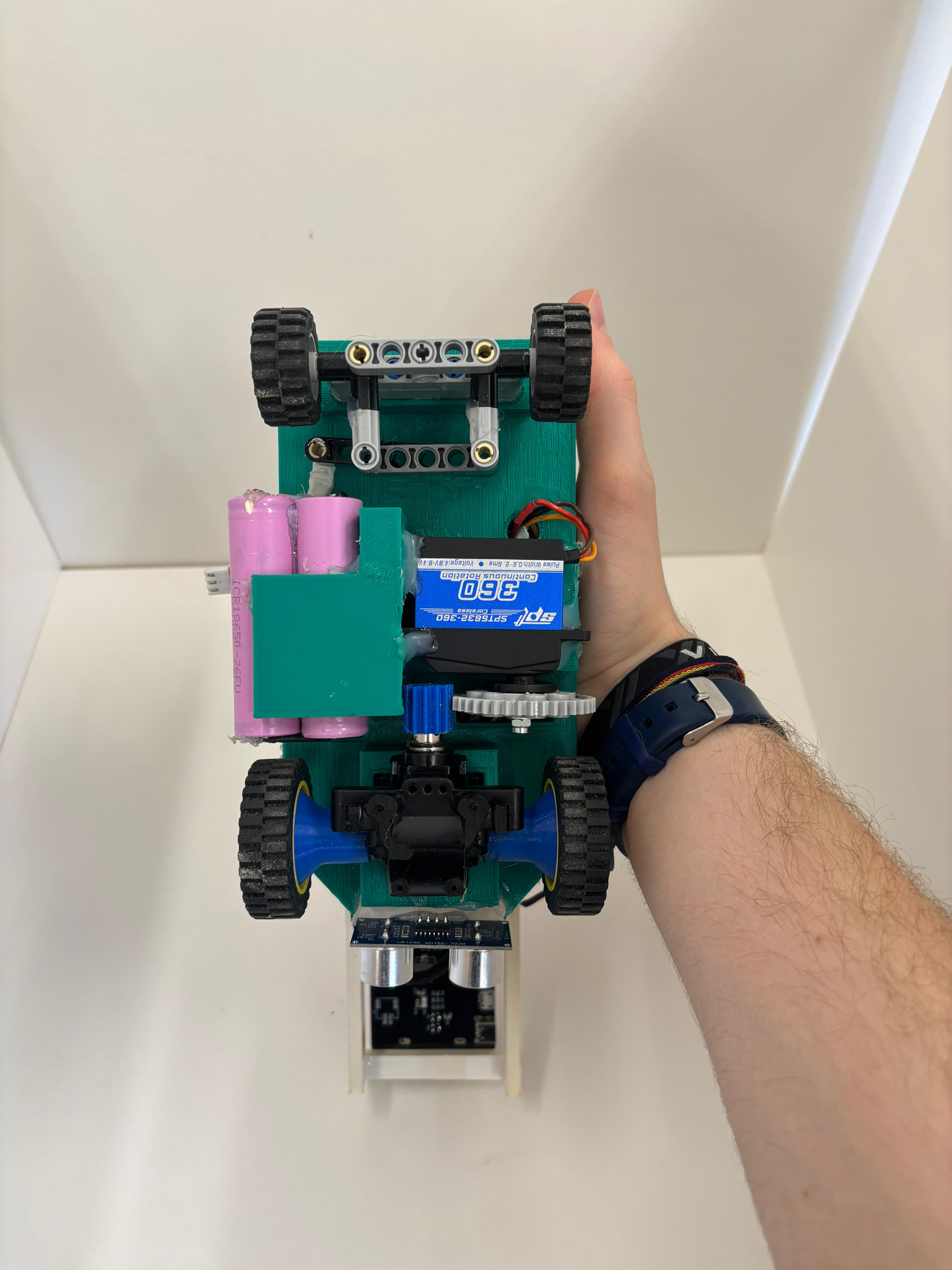 View from underneath the robot |
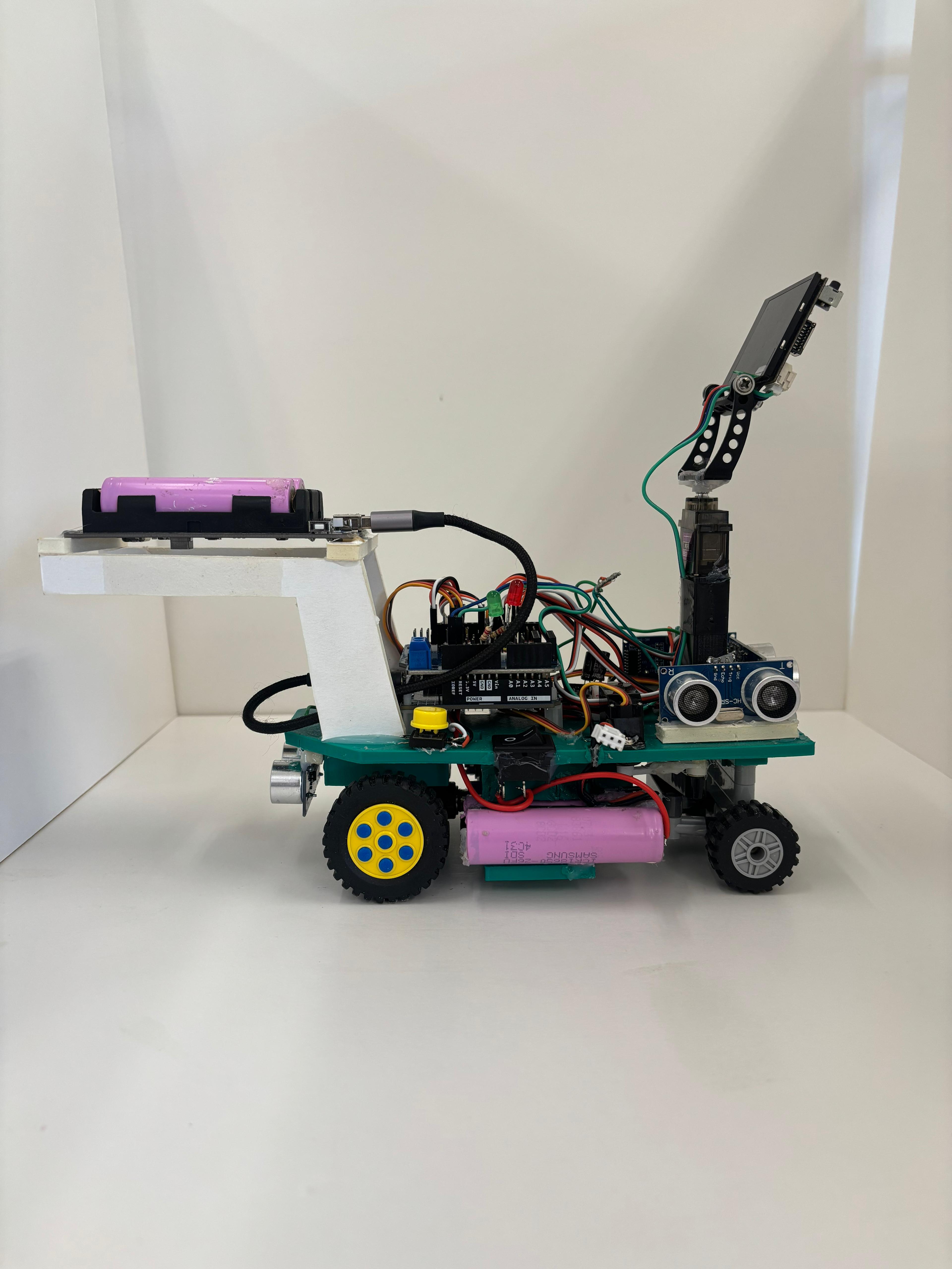 Robot’s right side view |
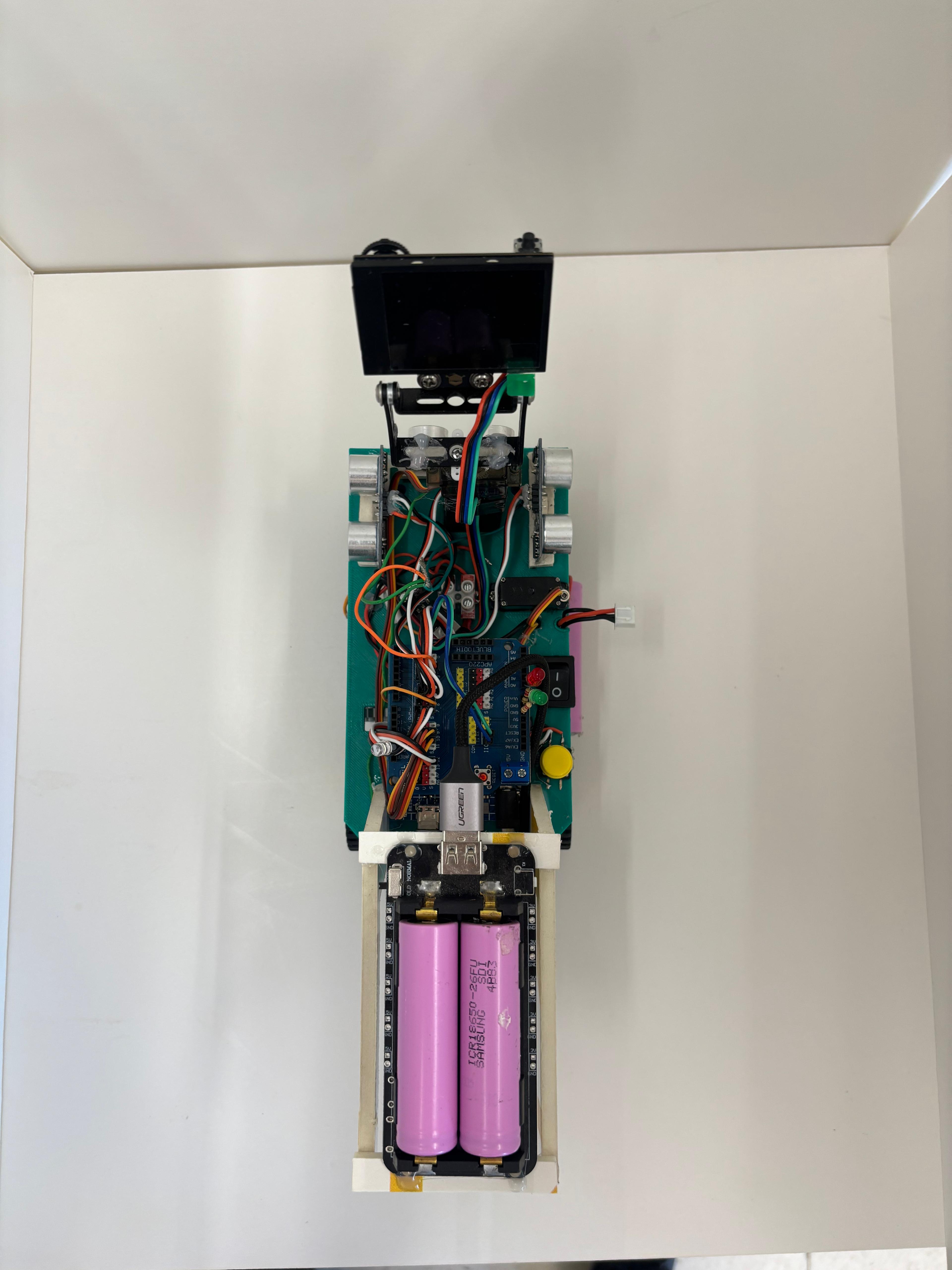 View of the robot's layout |
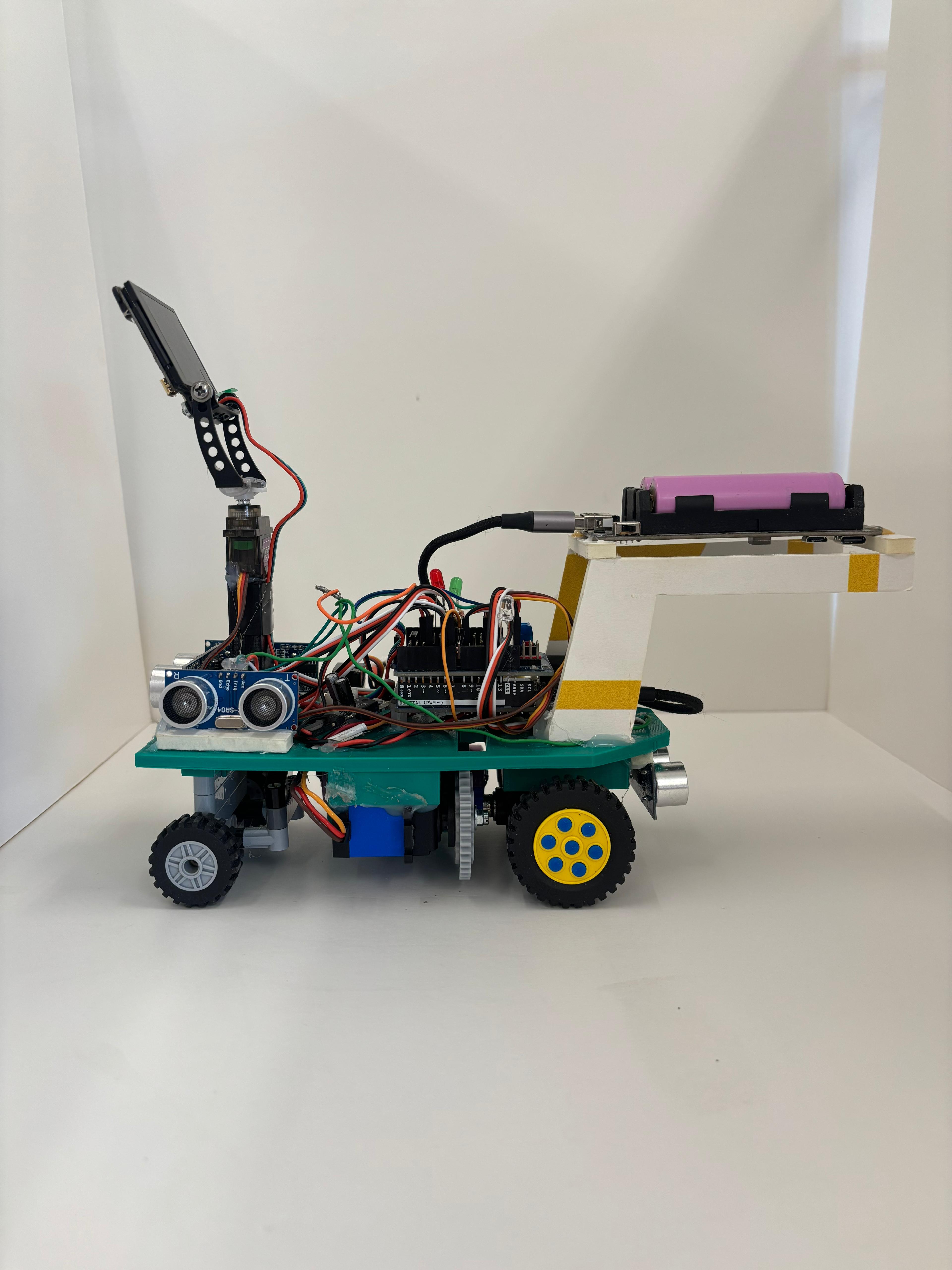 Robot’s left side view |
Other robot´s views
|
#### 2.2 Second Version (Raspberry)
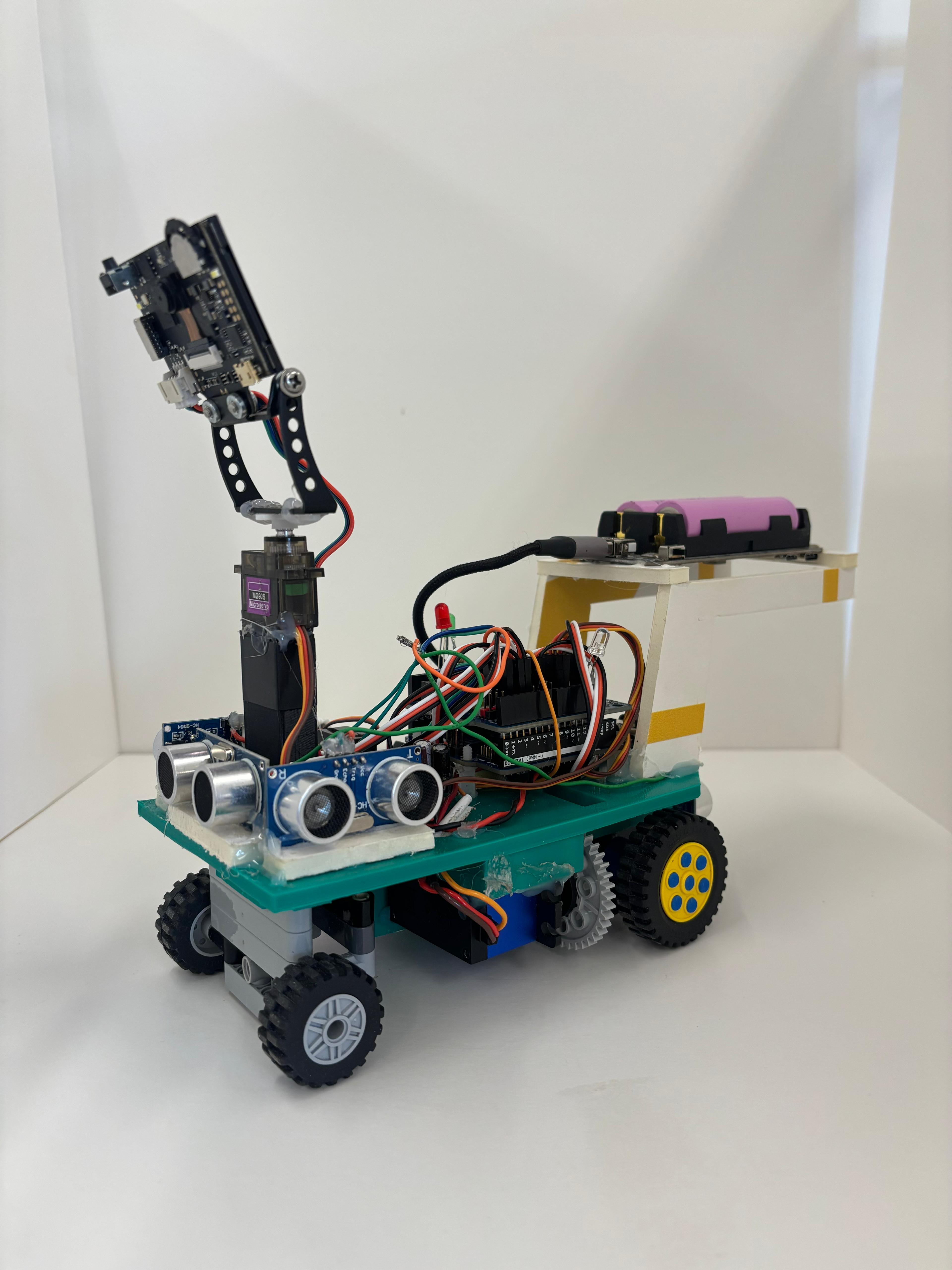
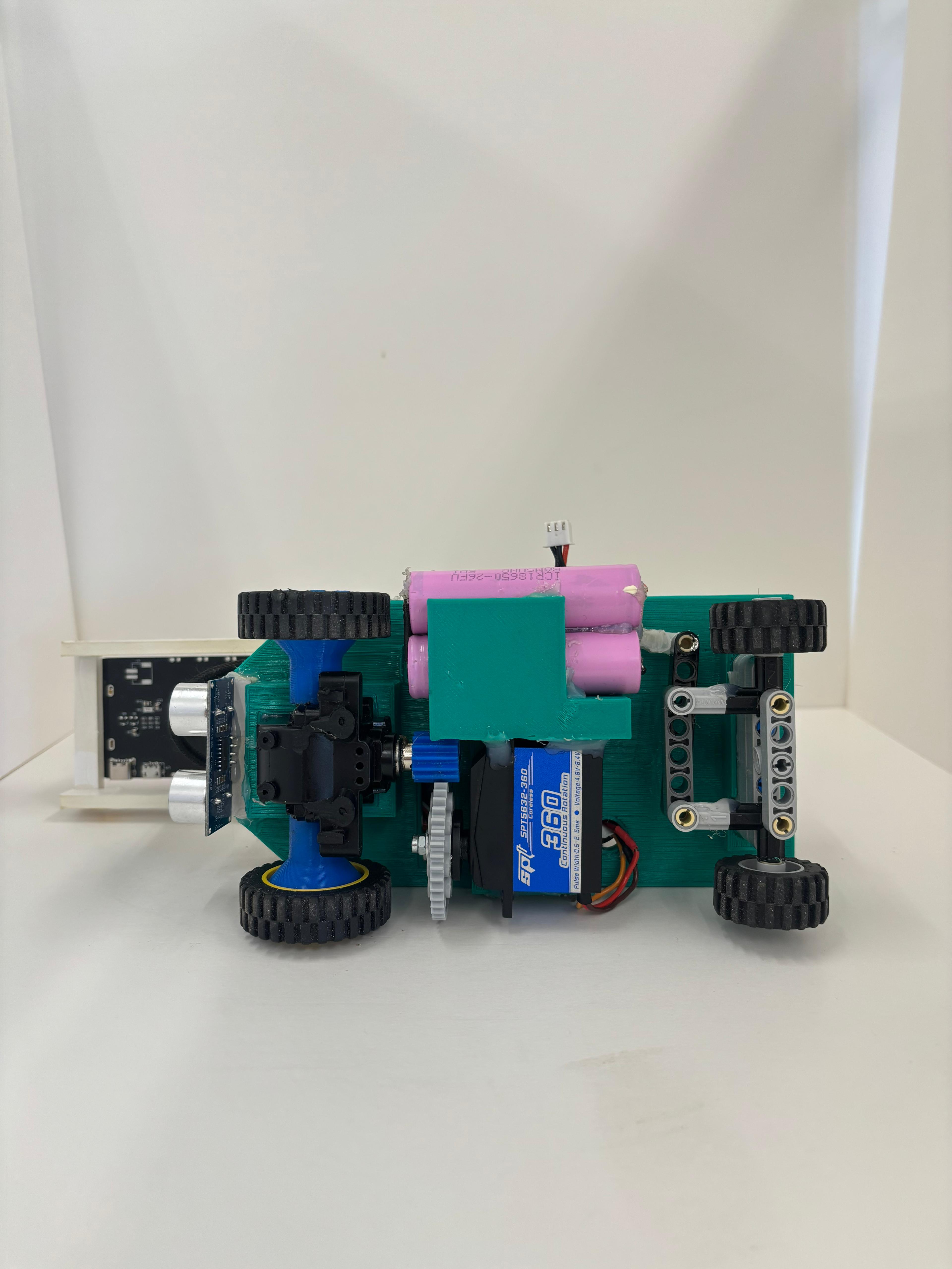
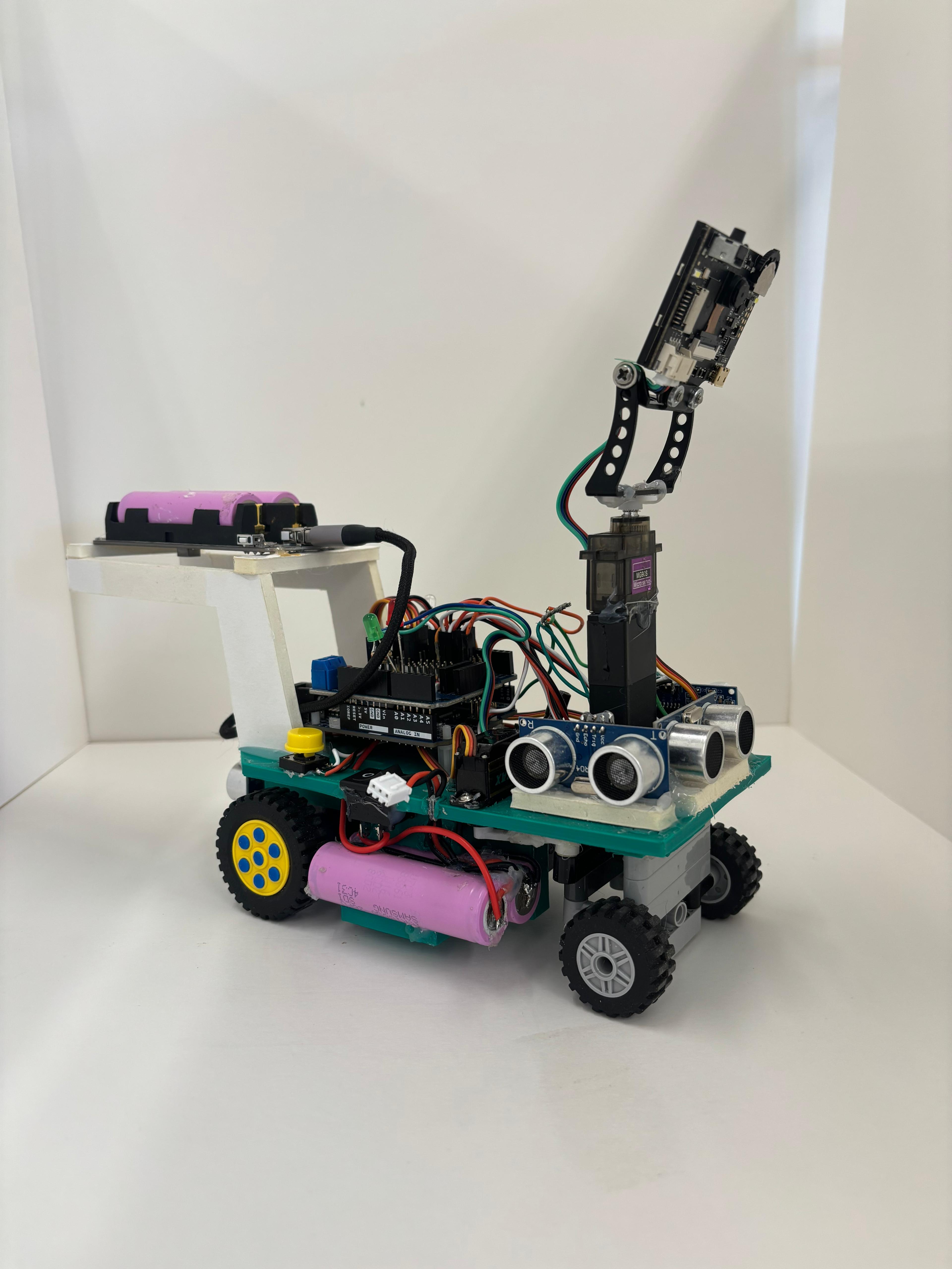
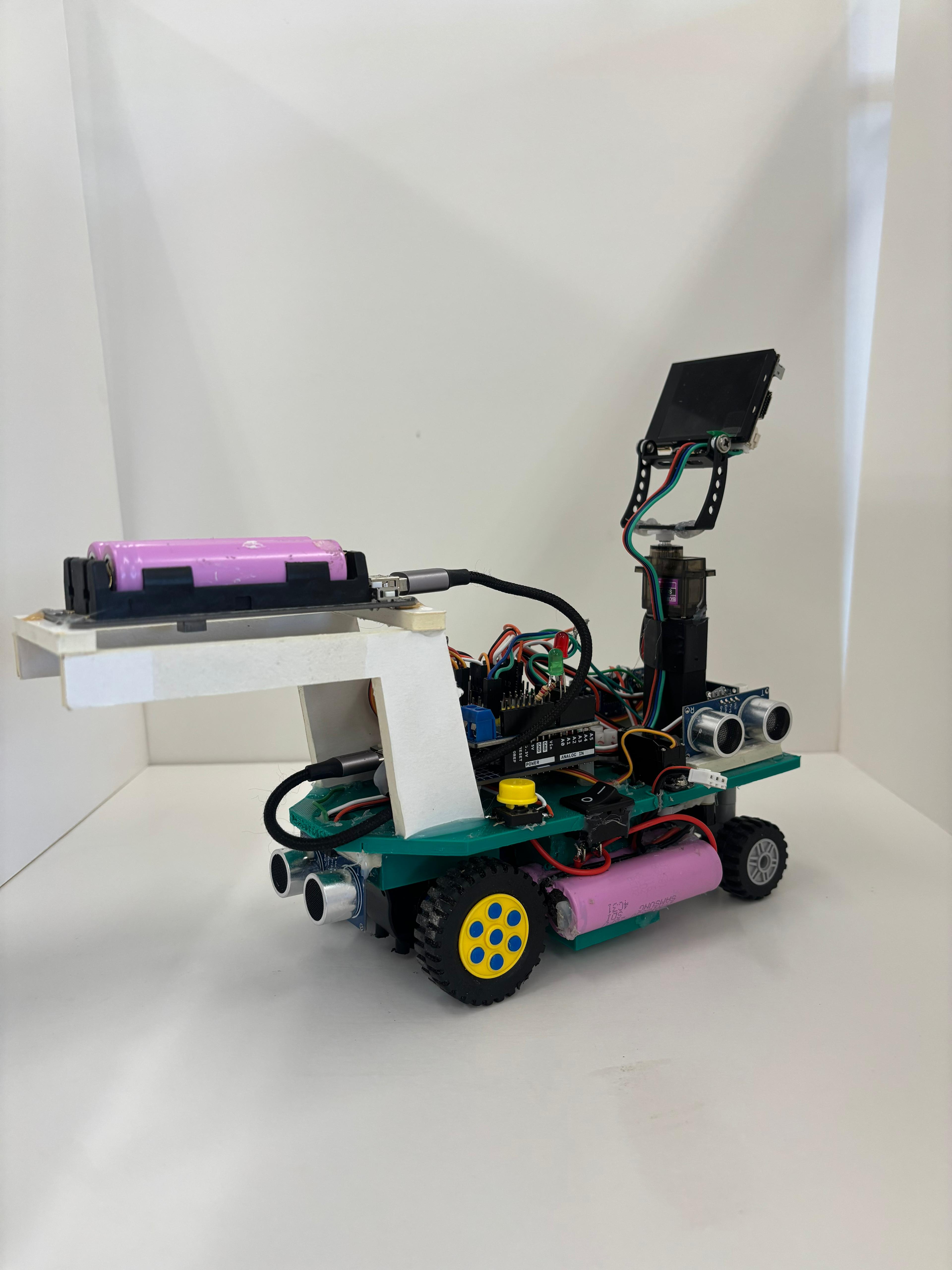
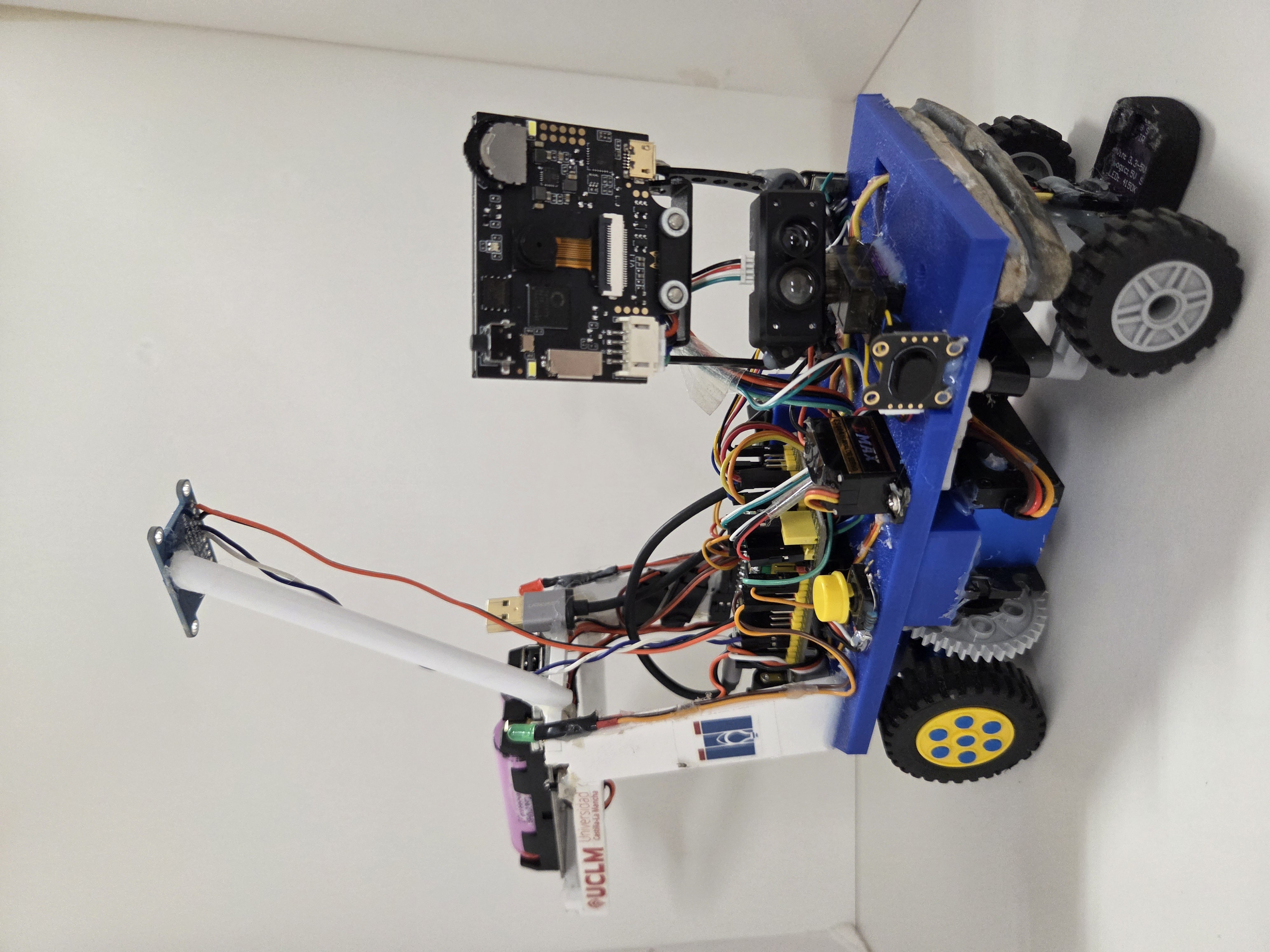
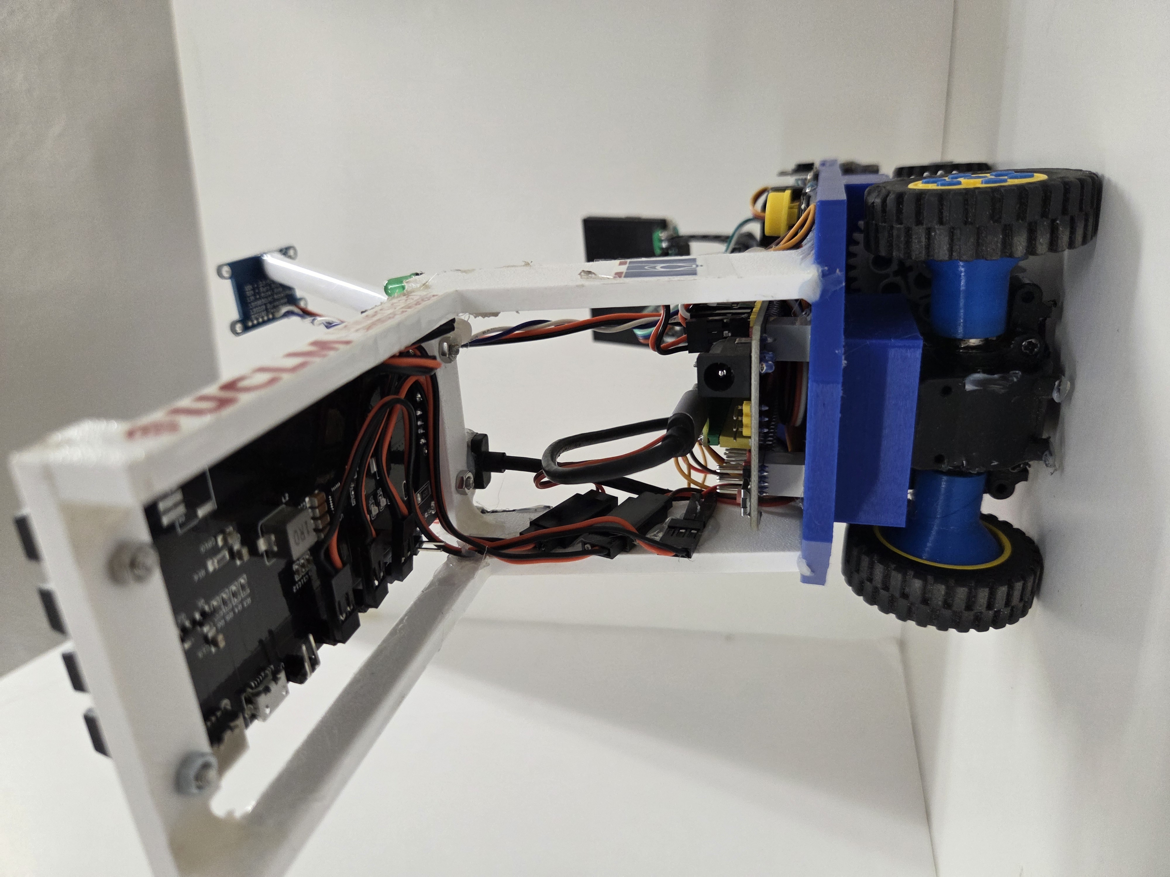
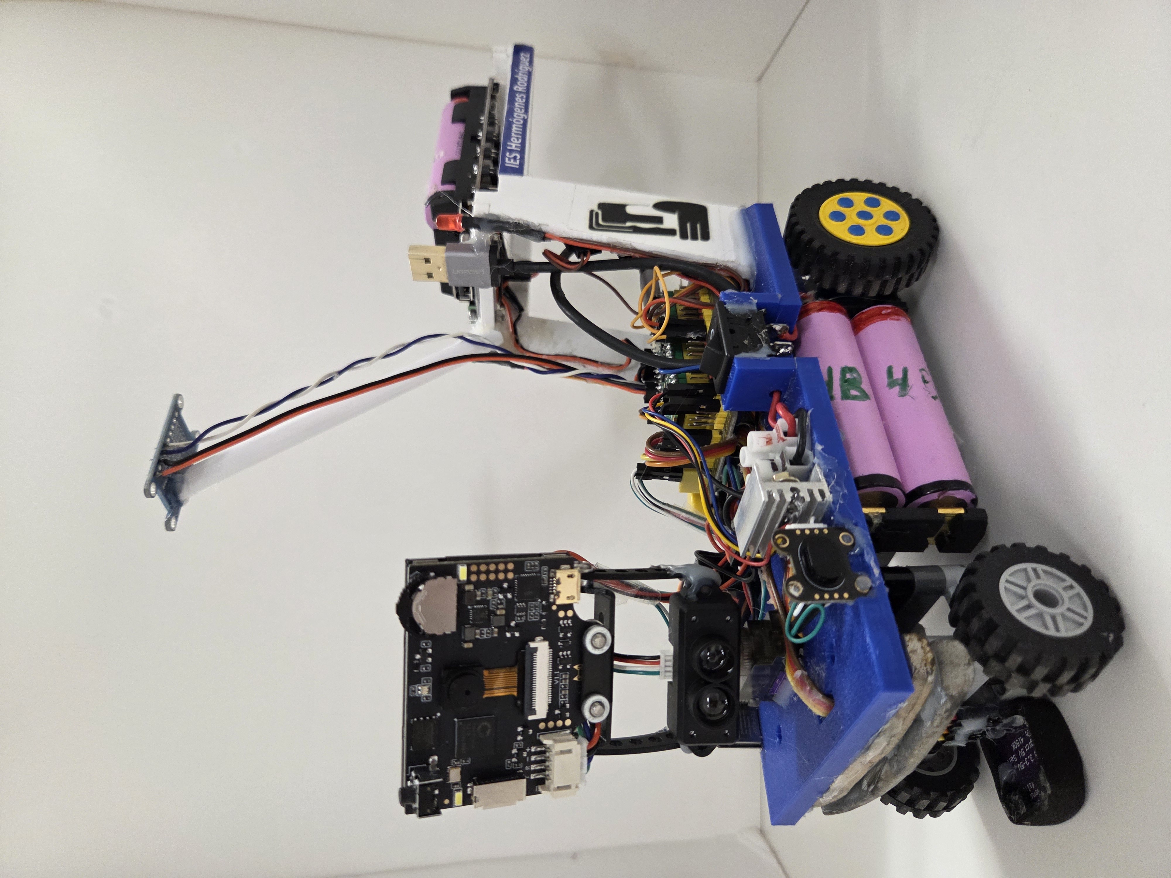
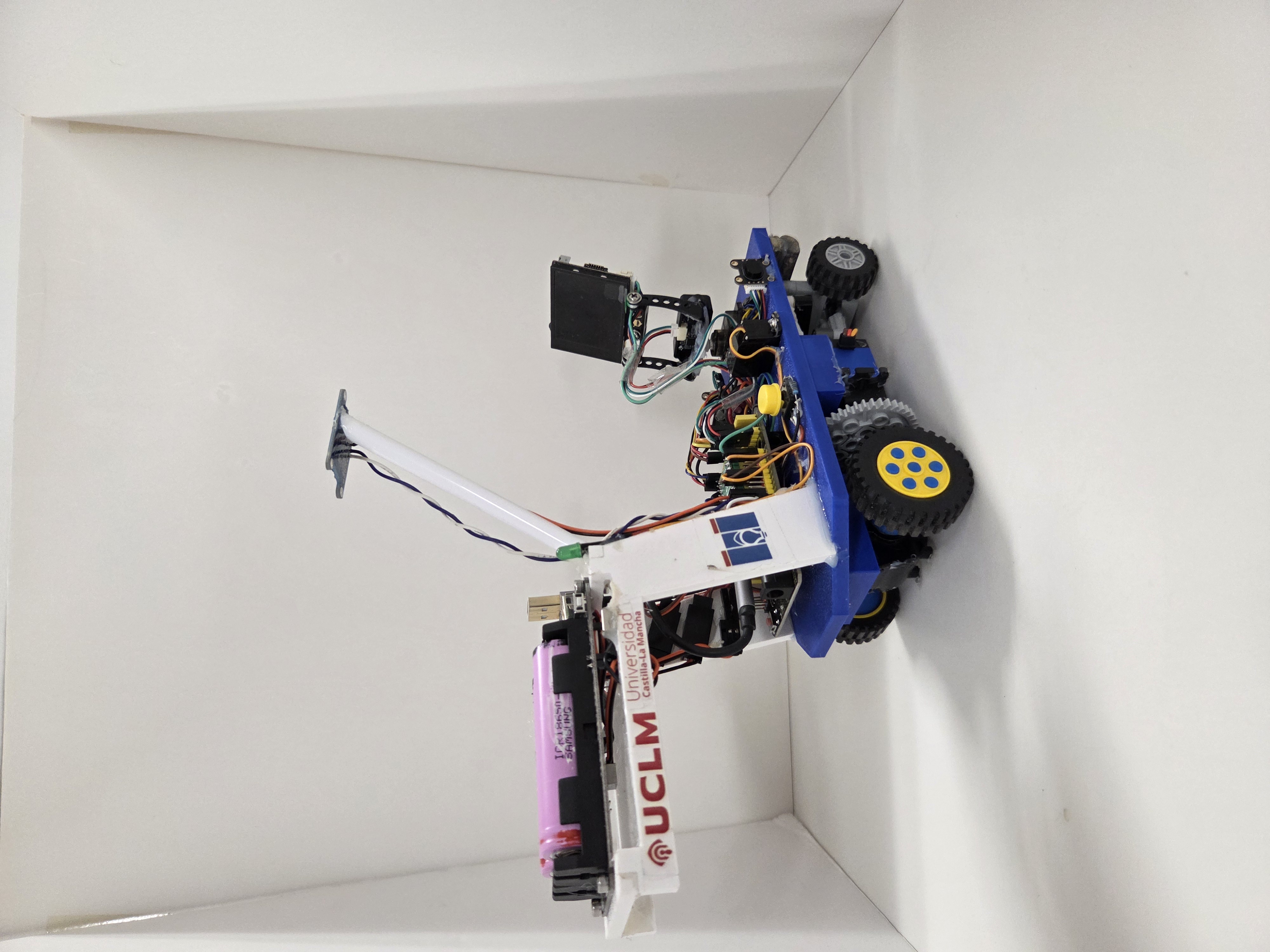
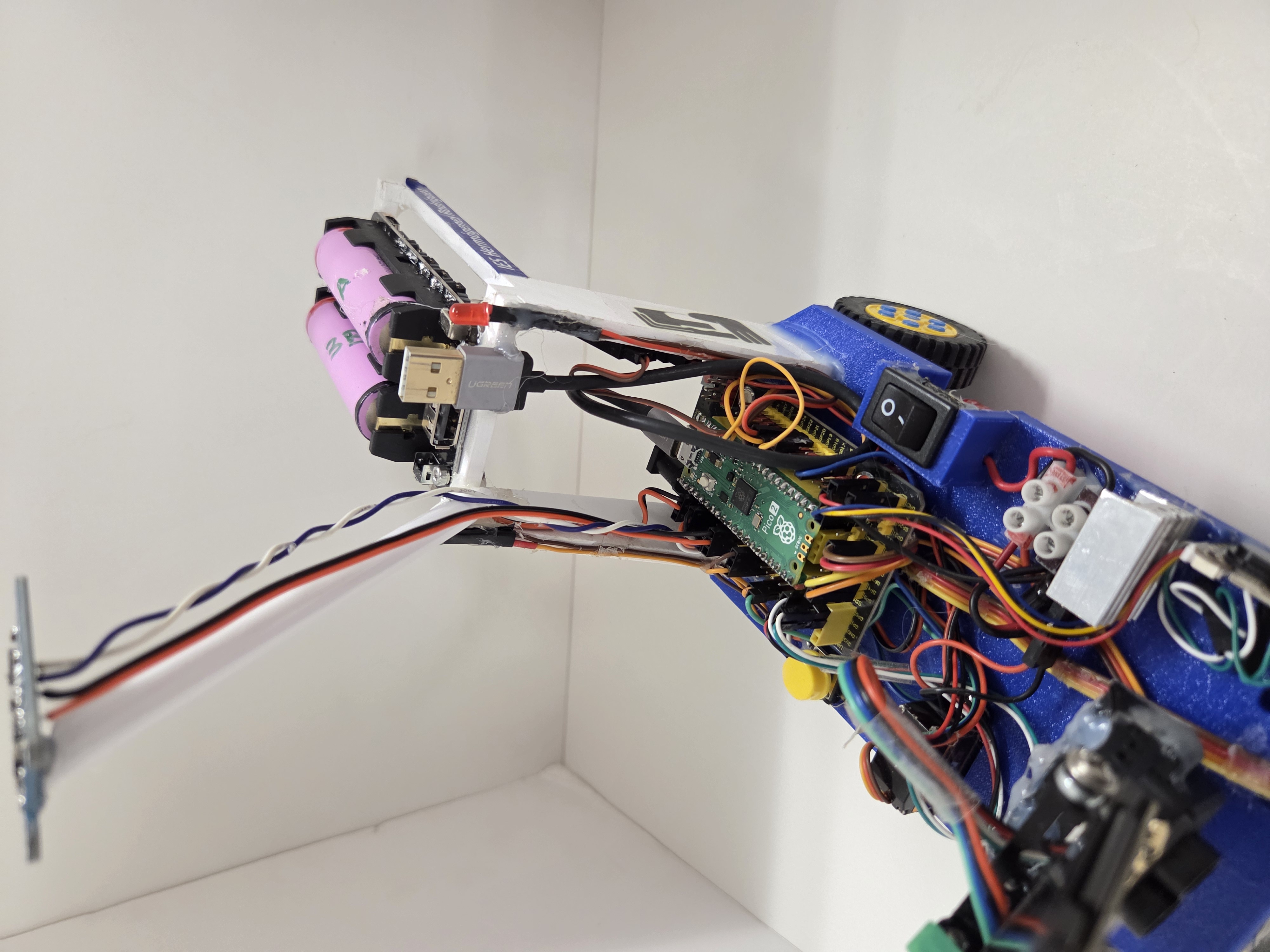
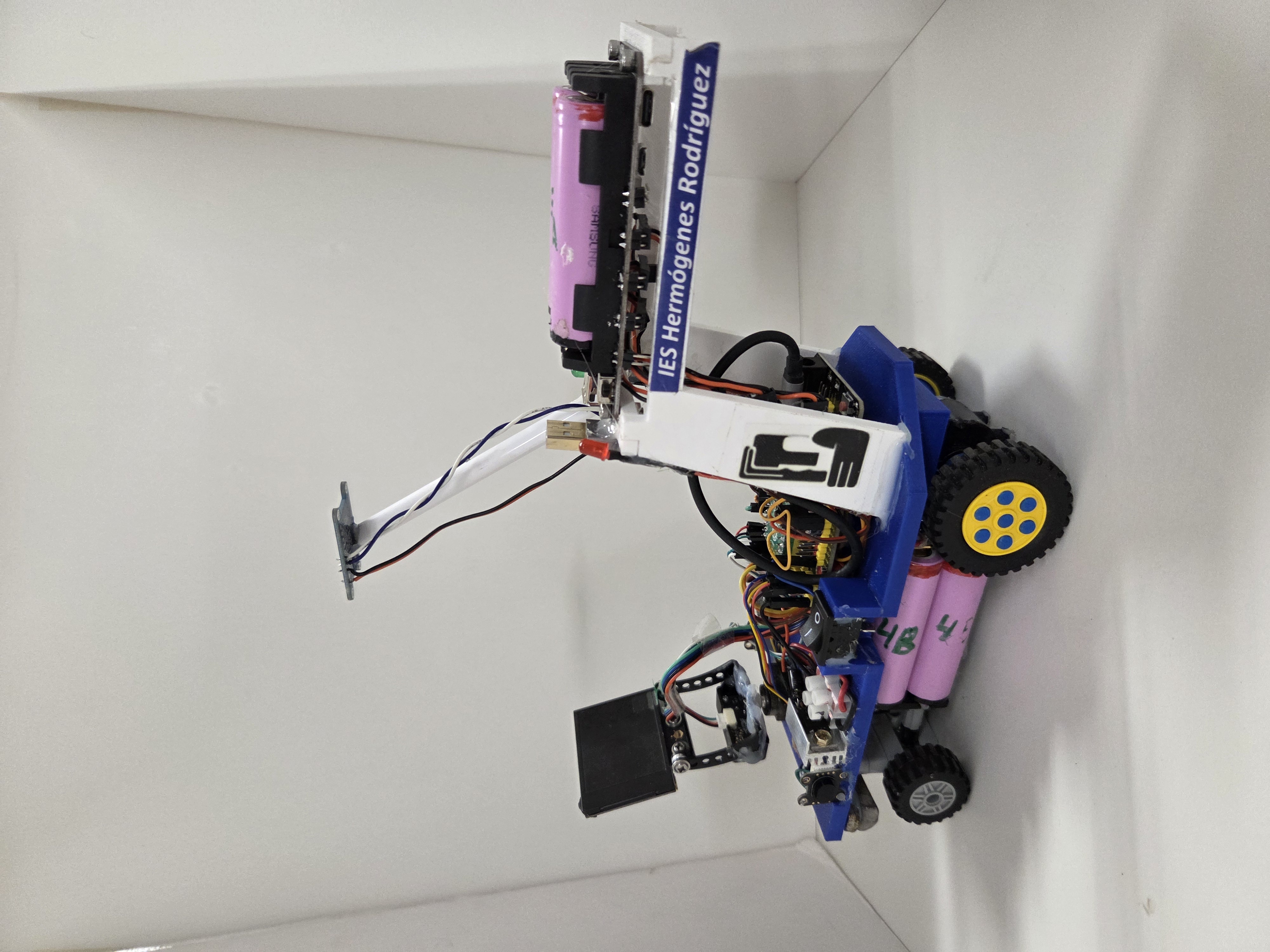
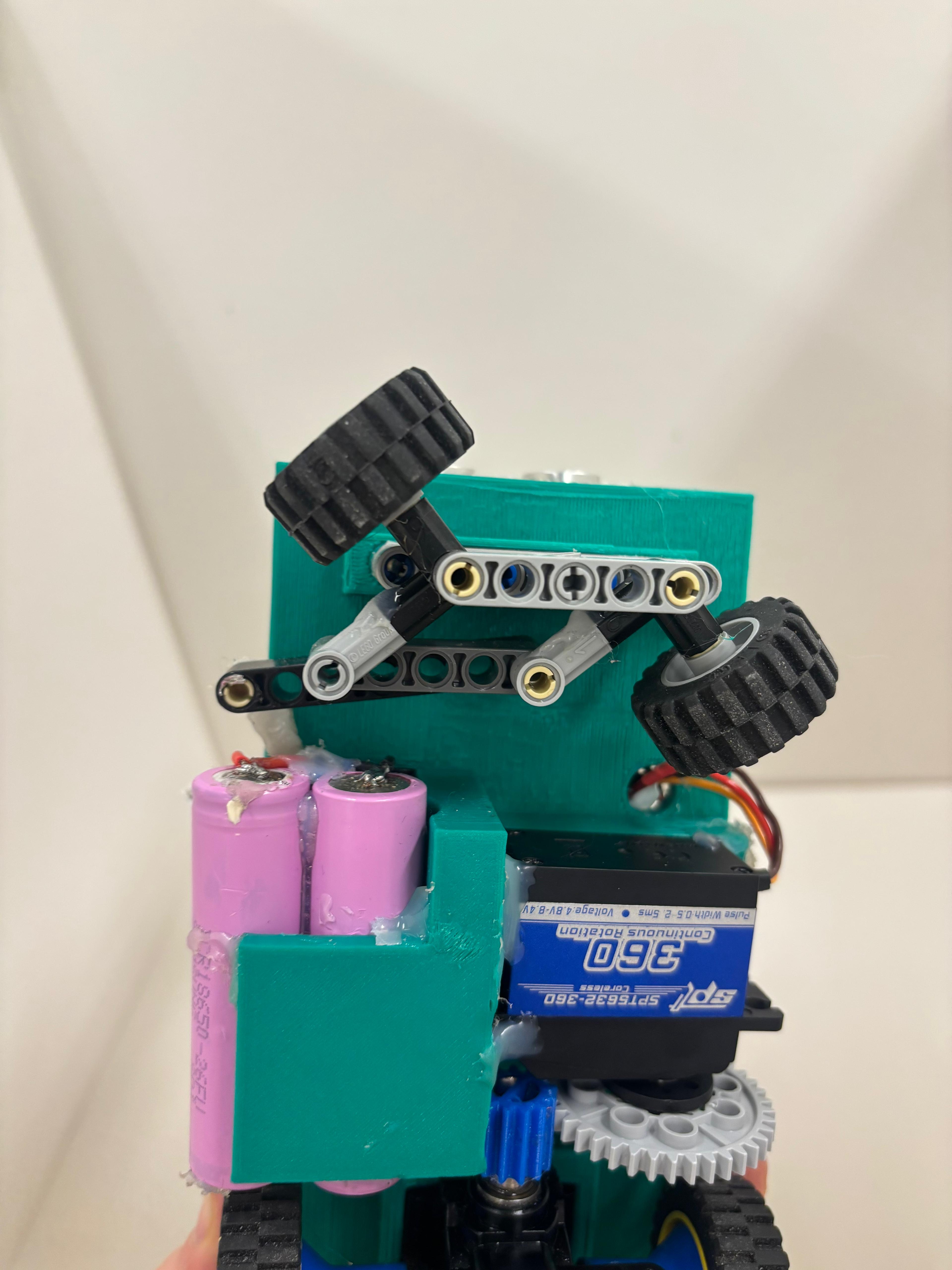
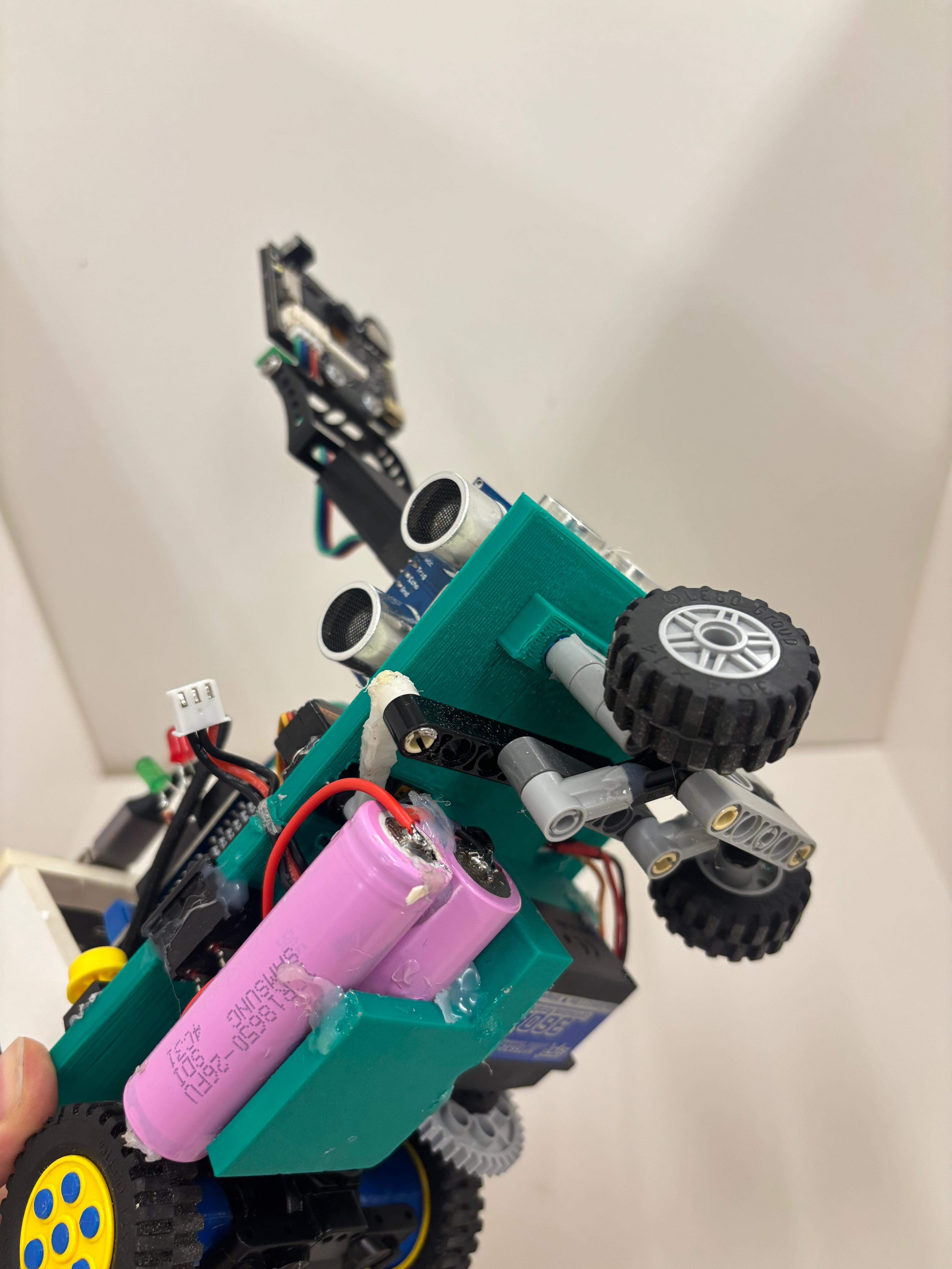
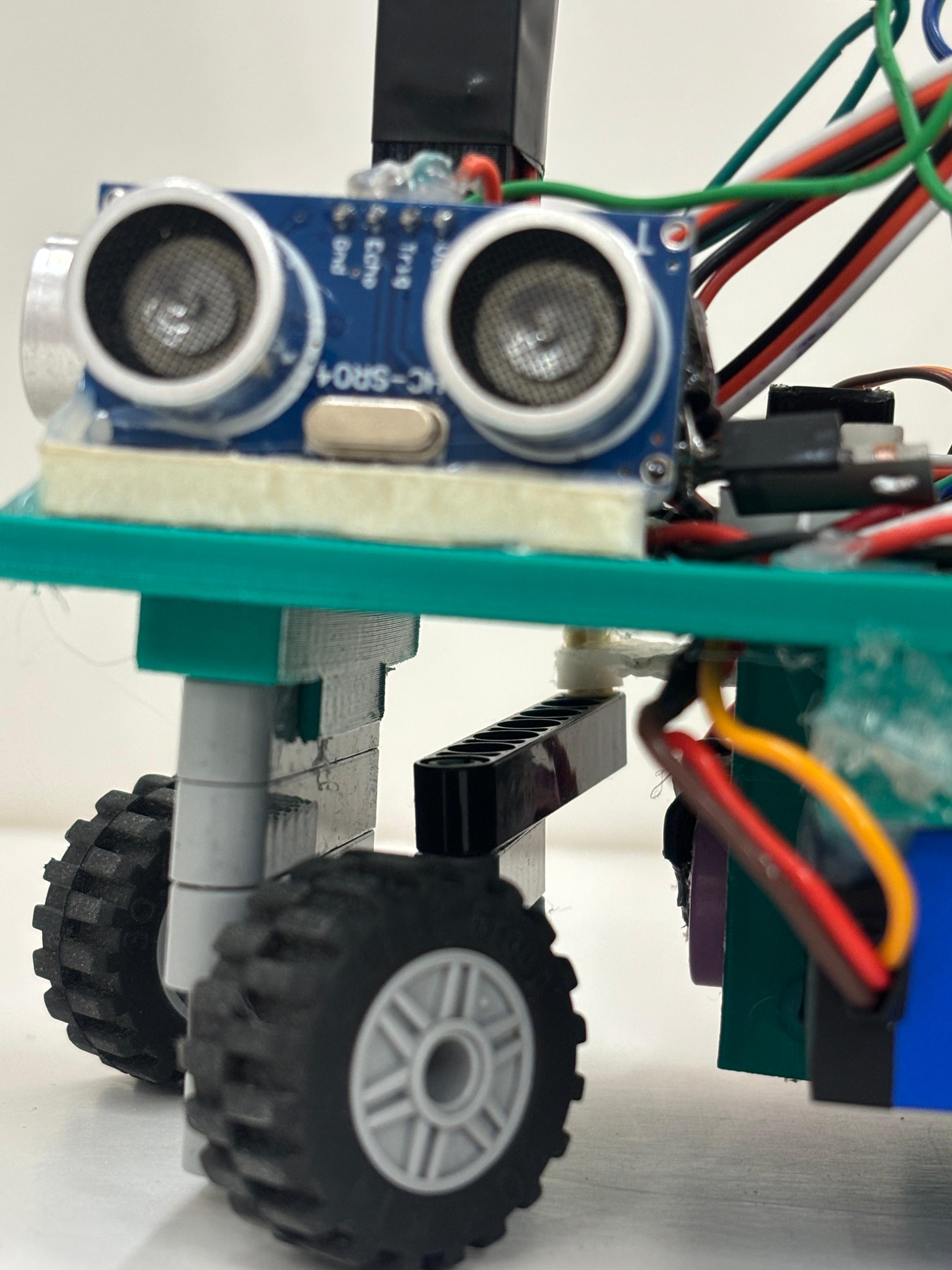
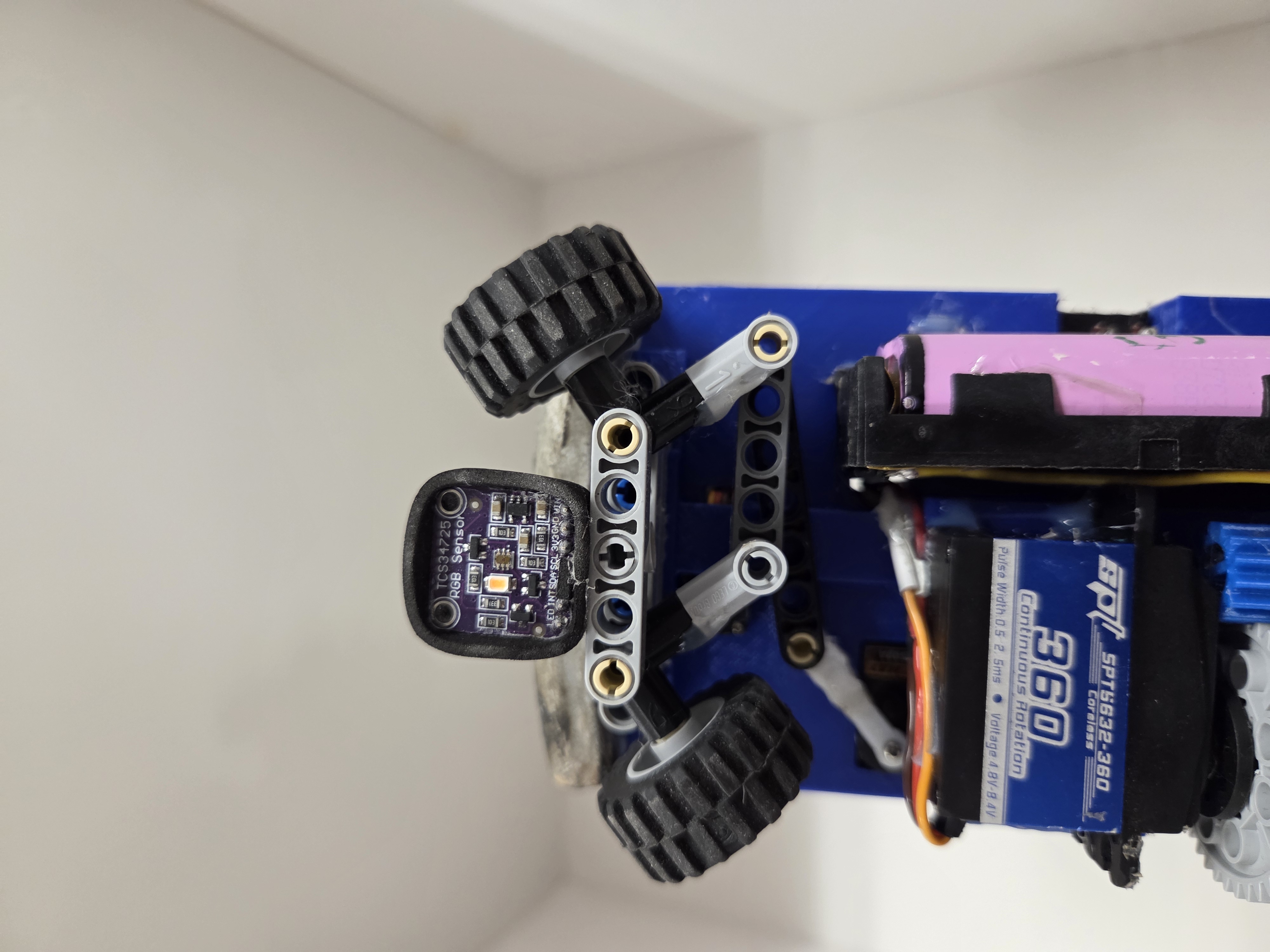
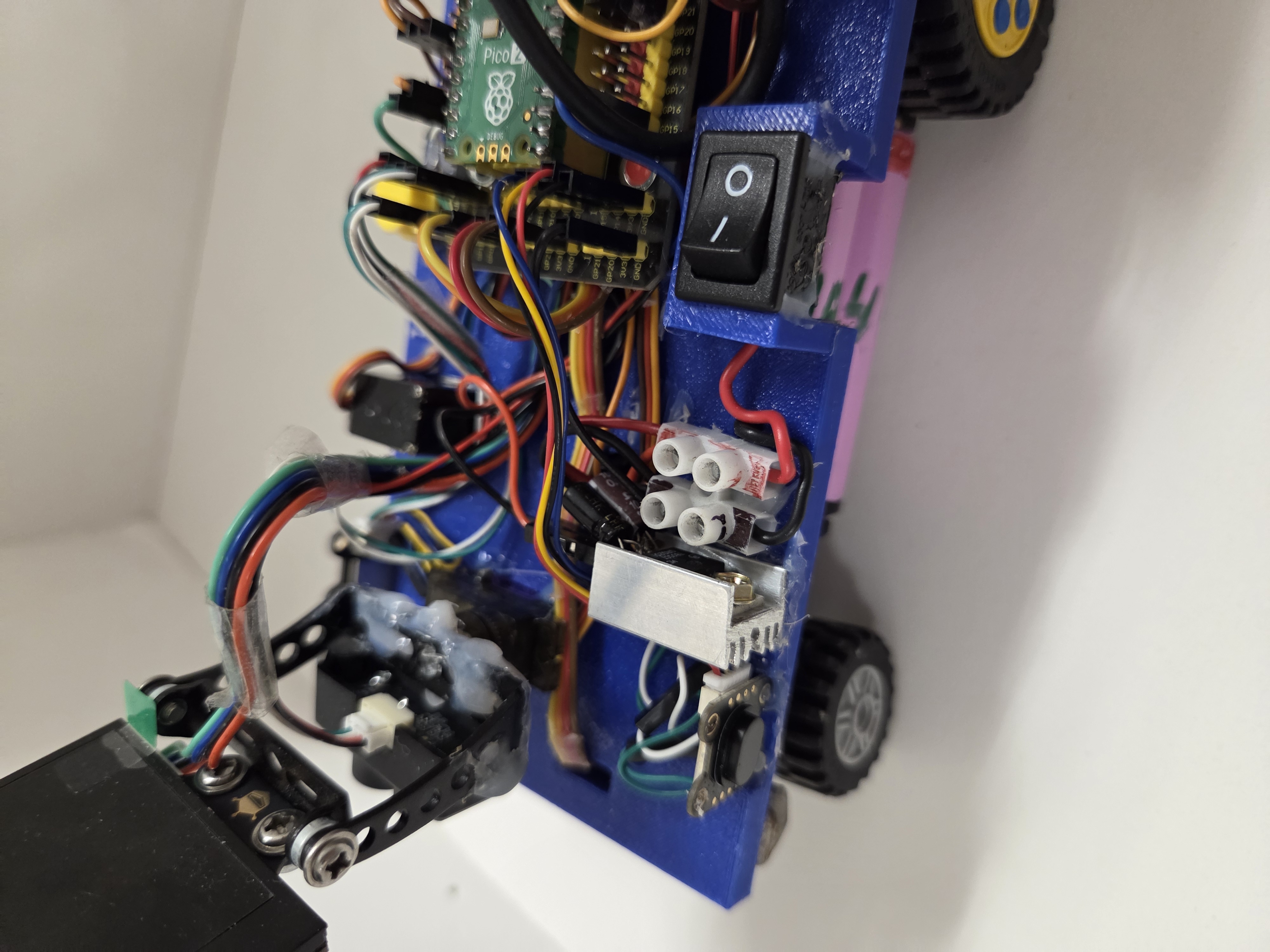
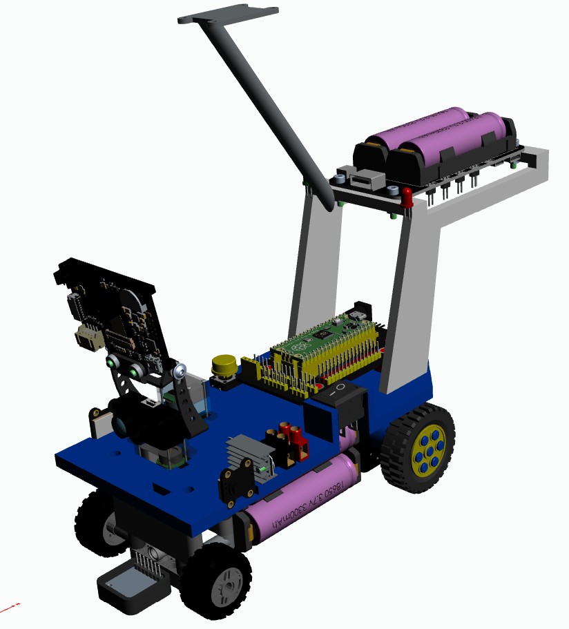
Here are some pictures of our robots second version to help with it´s reproducibility, and a table listing its main technical specifications:
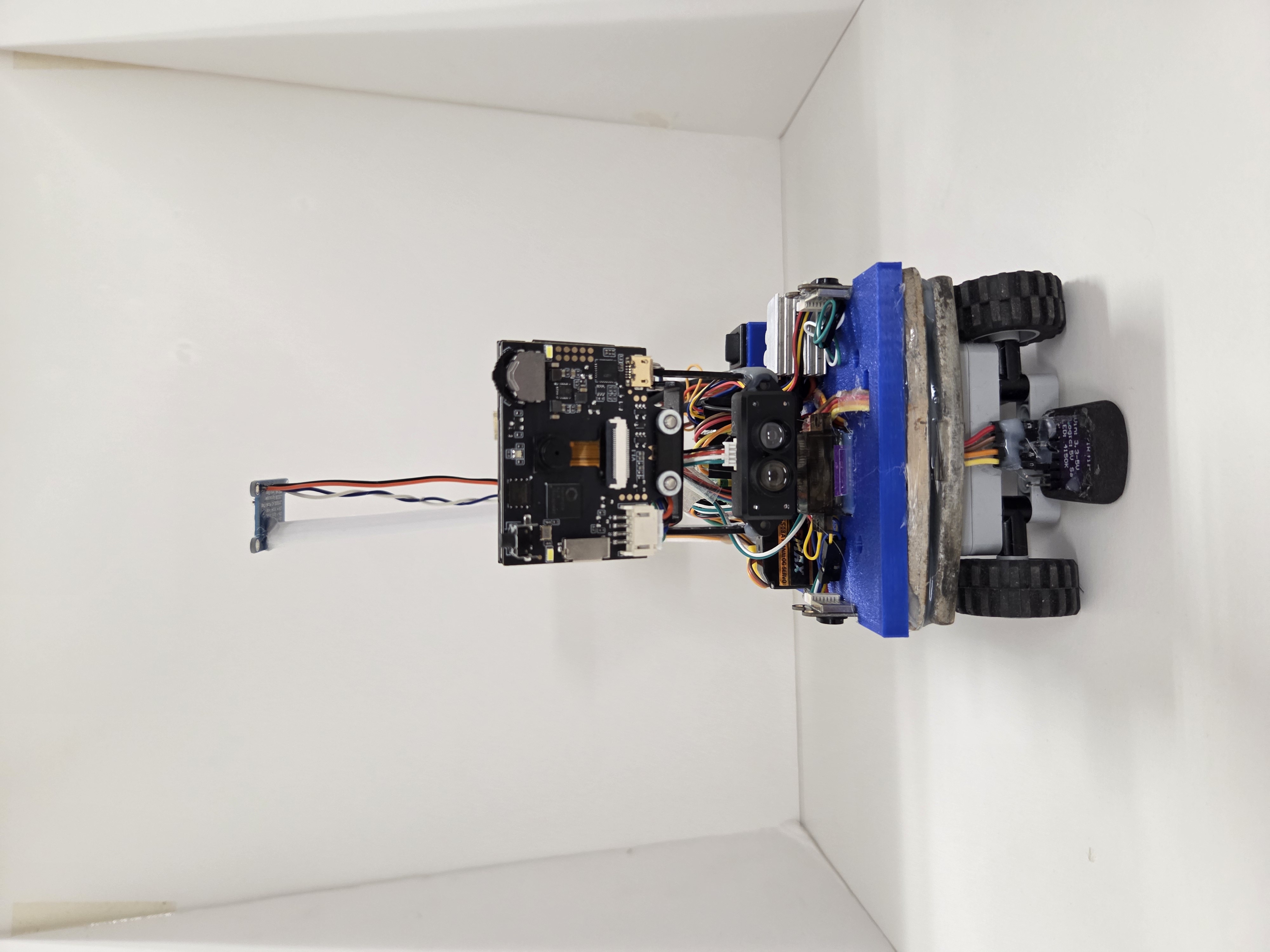 robot´s front view |
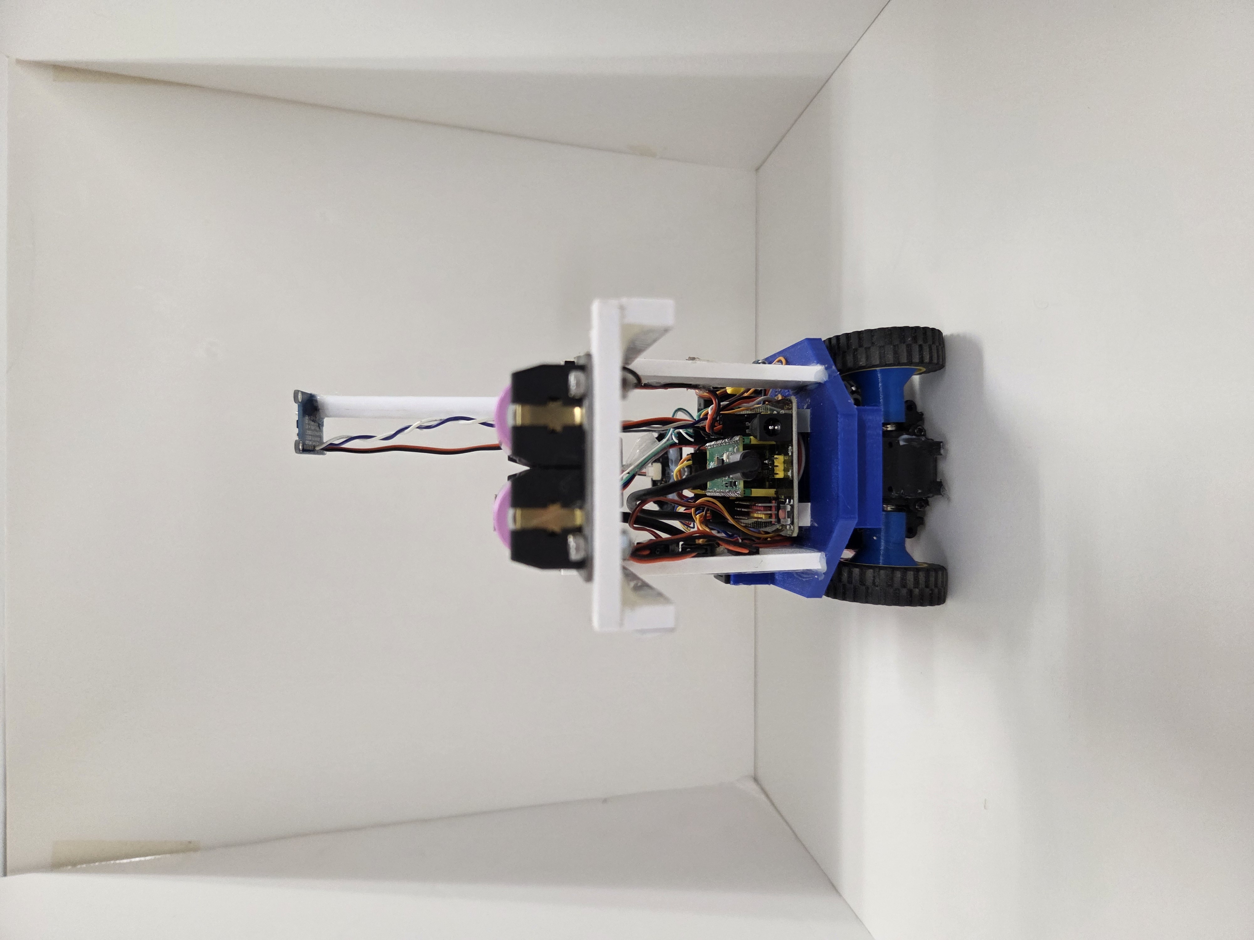 robot´s back view |
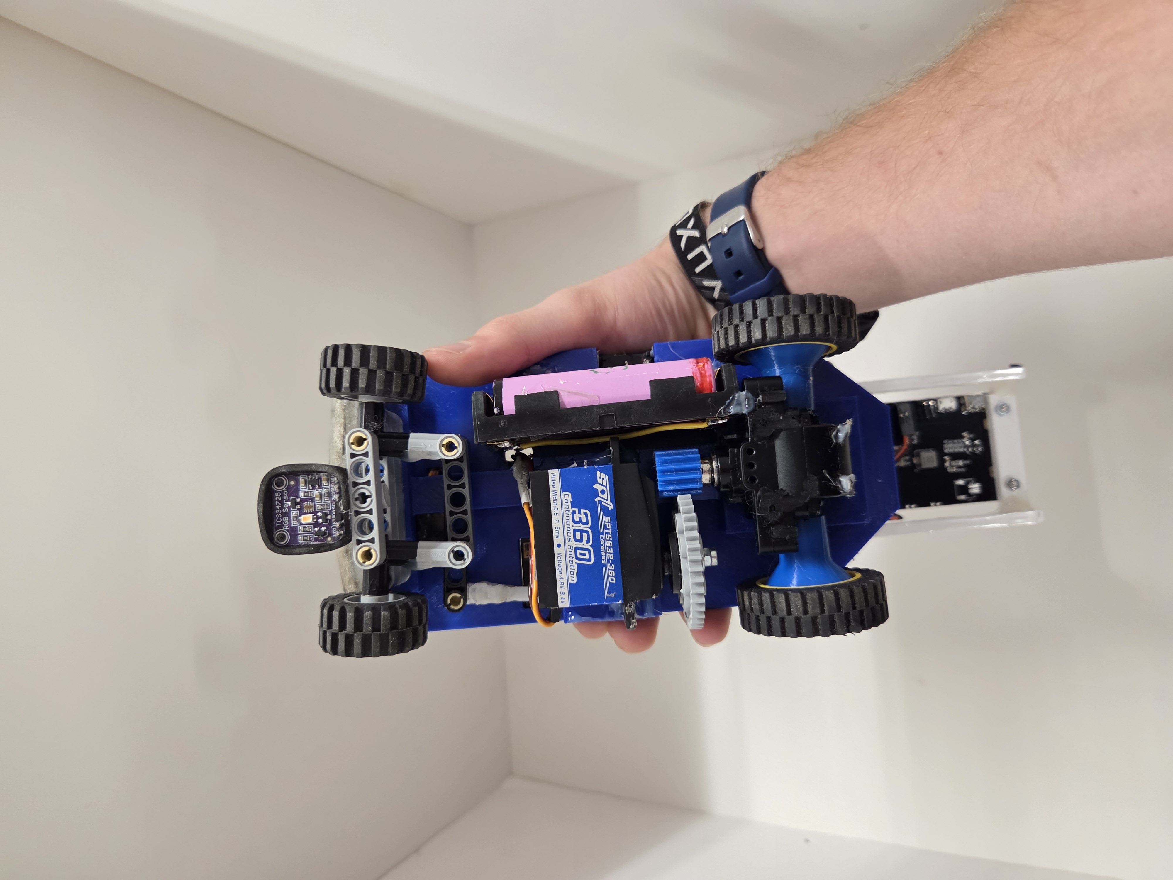 View from underneath the robot |
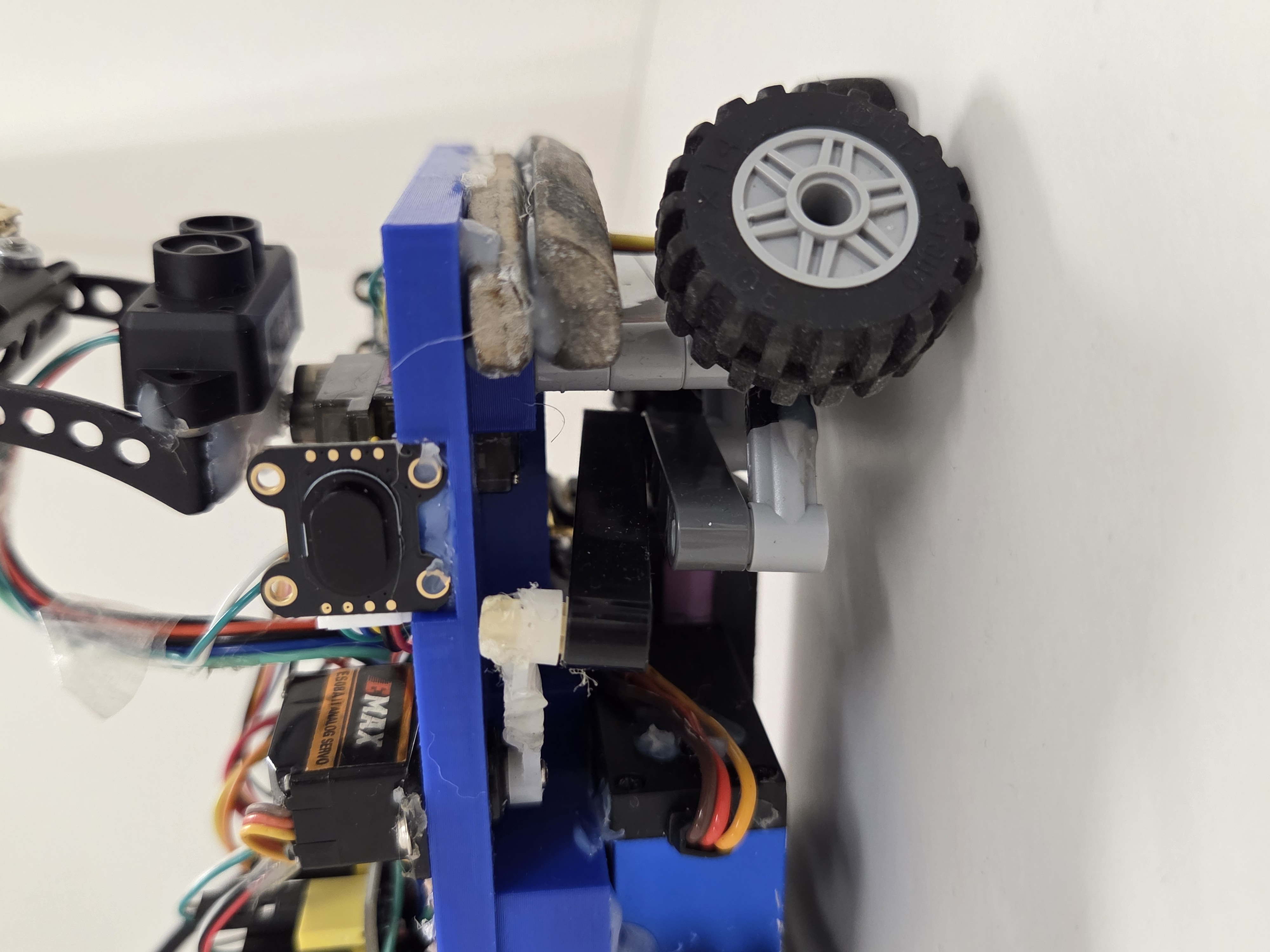
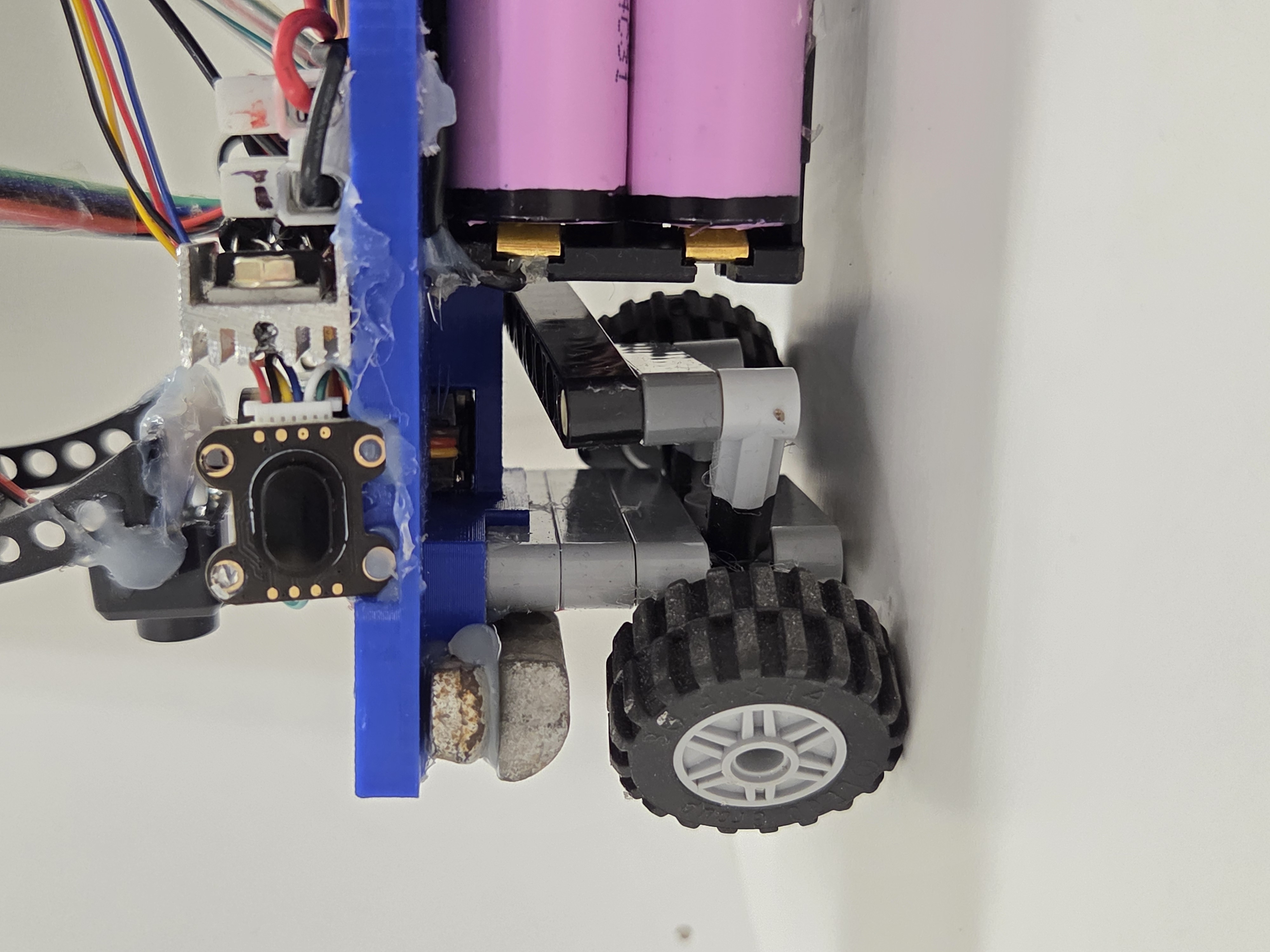
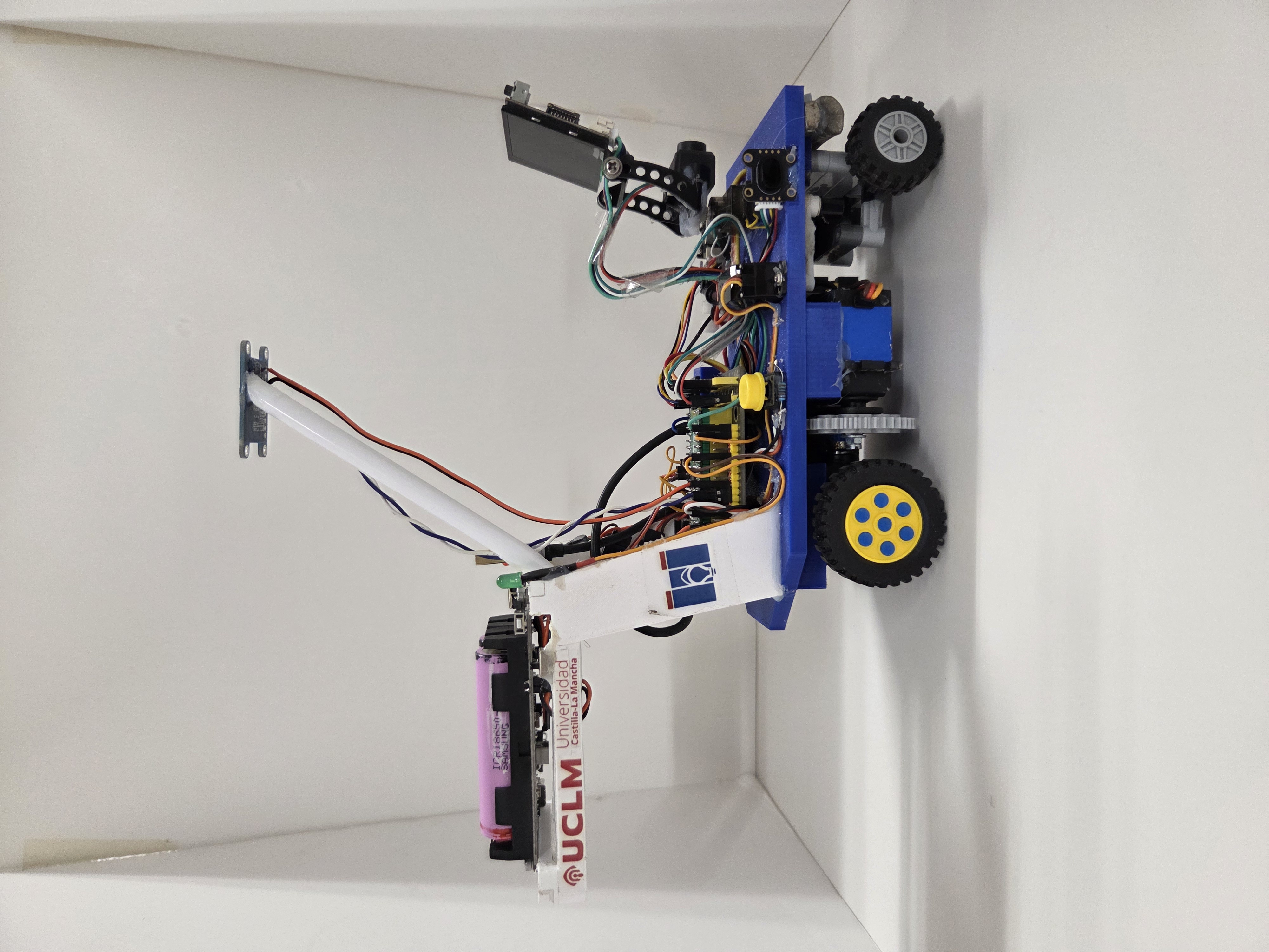 Robot’s right side view |
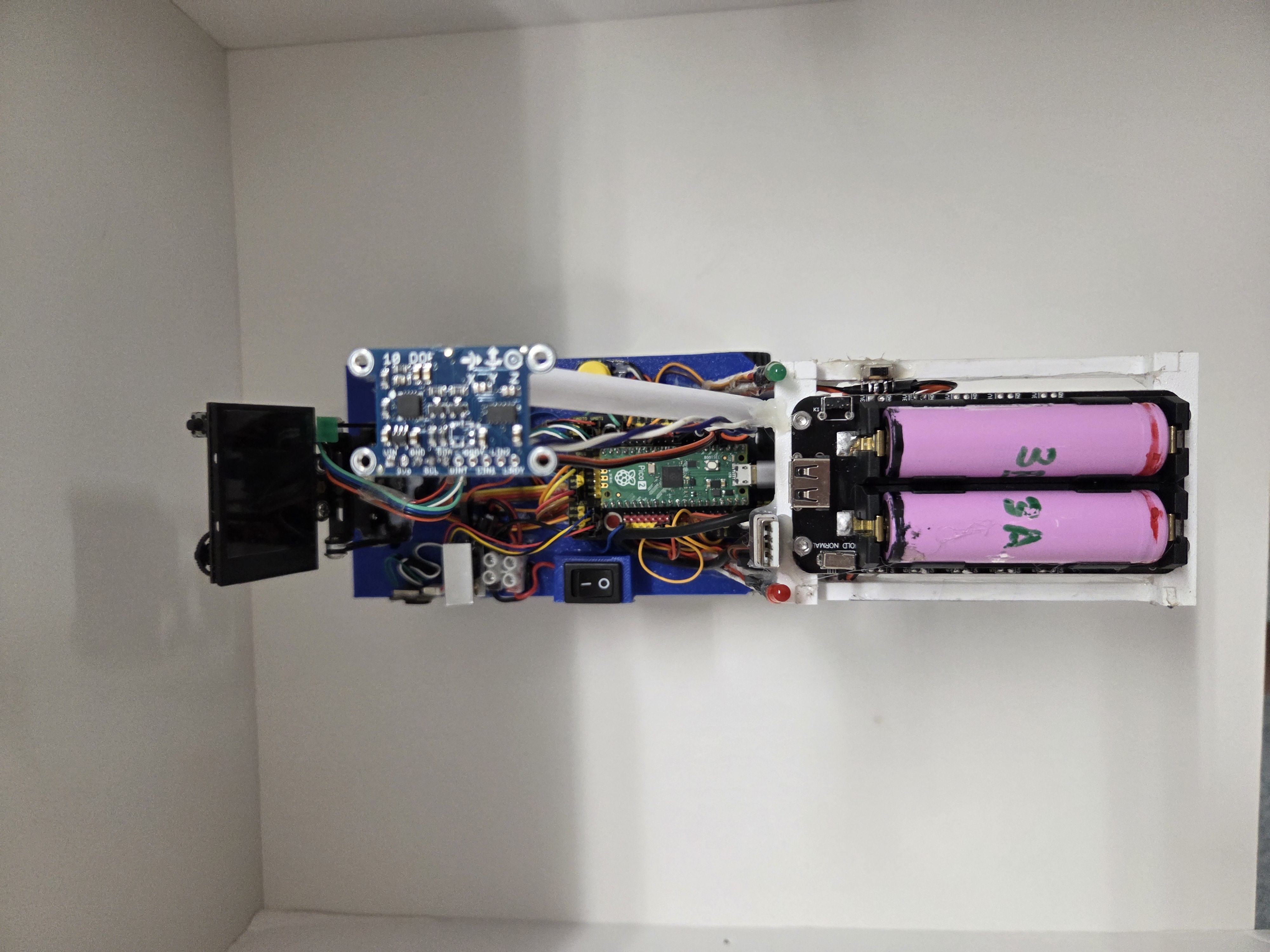 View of the robot's layout |
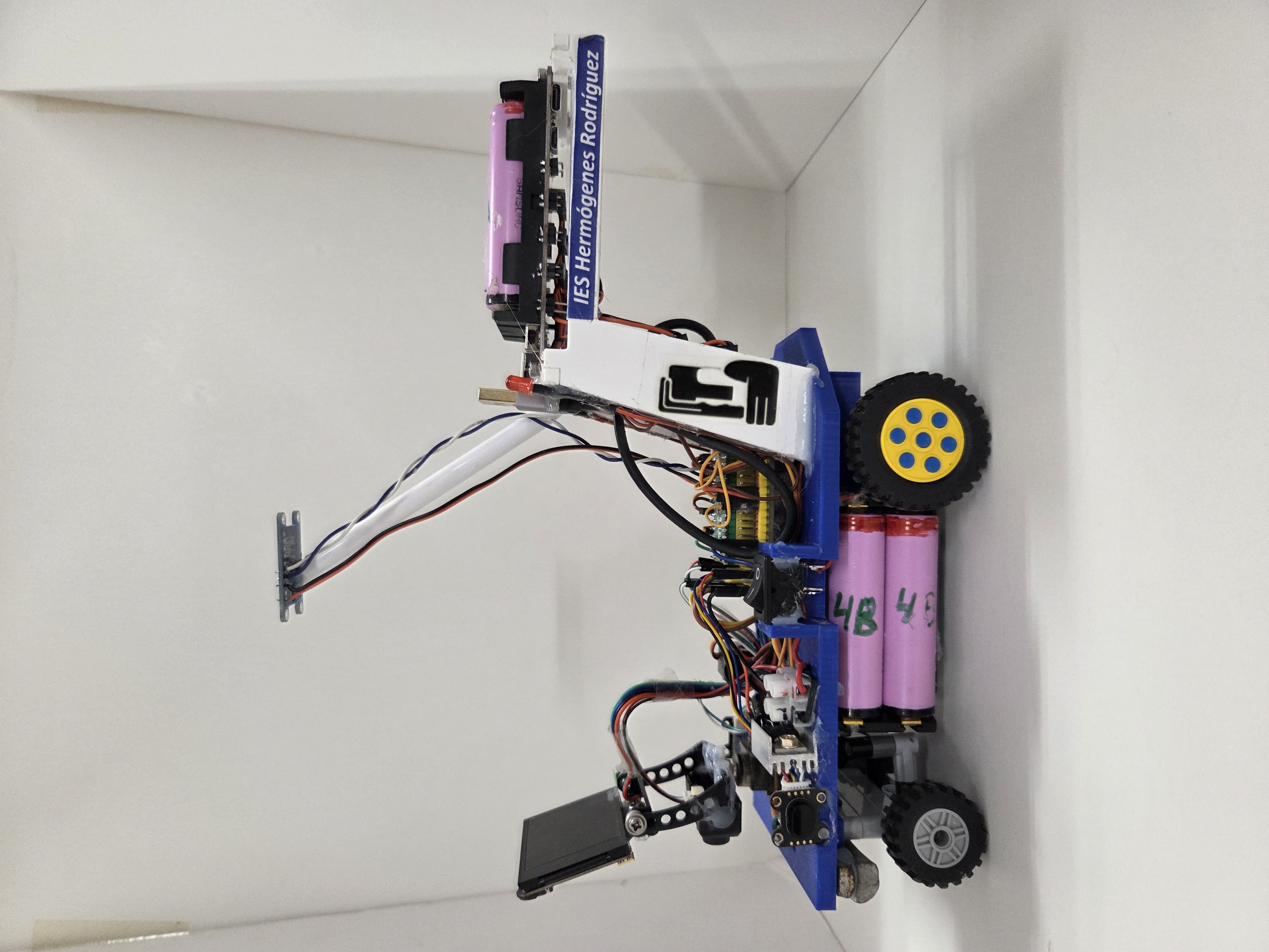 Robot’s left side view |
Other robot´s views
|
https://github.com/user-attachments/assets/58a79564-a333-4f58-b753-fa61092973e2
| Feature |
Value |
| Length |
27,5 cm |
| Width |
9,5 cm |
| Height |
23 cm |
| Weight |
796 g |
| Maximum stable speed |
0,211 m/s |
| Torque |
2,5-4 N |
| Maximum stable revolutions |
1,495 revolutions/s |
| Microcontroller |
Raspberry Pi Pico 2 |
| Vision system |
HUSKYLENS module |
| Motor system |
DC motor |
| Steering system |
Ackermann steering |
| Transmission system |
Gear transmission |
| Motor |
SPT5632-360 servo |
| Steering motor |
MS18 servo |
| Batteries |
Samsung ICR18650-26FU batteries |
| Camera processing speed |
11–30 FPS |
| Maximum current draw |
1,5 A |
| Average lap time |
25 s |
| Chassis type |
Custom PCB chassis |
#### 2.3 Final Version (Raspberry)
Here are some pictures of our robots final version to help with it´s reproducibility, and a table listing its main technical specifications:
### 3. 📝 Daily documentation
Here you can find the detailed progress of the MINAGURO team during the tournament:
🔍 March 2026
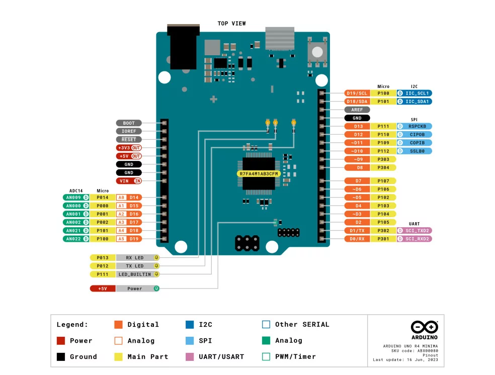
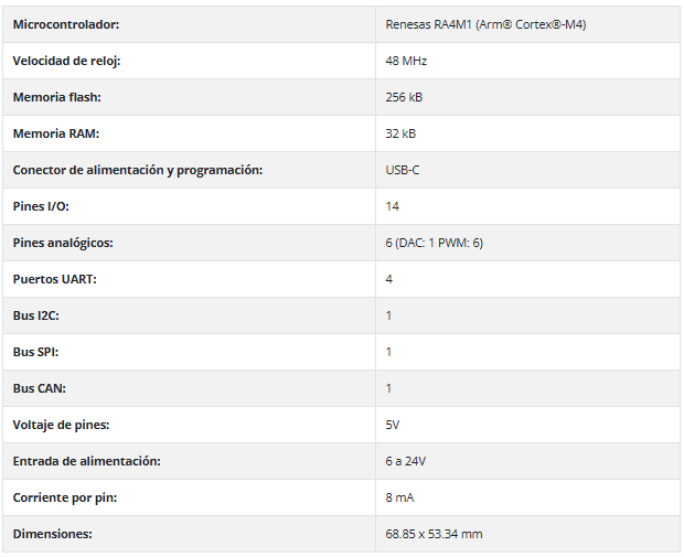
* **04/03/2026:** We began dividing up the work among the group, agreeing that Miguel and Rocío would handle the robot and the documentation, and Natalia and Guillermo would handle the programming. We also discussed the general features of the project. After watching videos of models from previous years and given that the robot’s maximum dimensions are 30x20 cm (which we felt was too large), we decided to try to make it as small as possible, since smaller robots tend to be more mobile and would also make it easier to avoid obstacles. Regarding the choice of the base board, we had four options: Raspberry Pi, Arduino R3, and Arduino R4 (with and without Bluetooth/Wi-Fi modules). Of these, we chose the Arduino R4 Minima (without Bluetooth/Wi-Fi) because it has a much faster protocol and more memory, and because the C++ used is a programming language we were already familiar with, which would make it easier for us to program; furthermore, it is compatible with the HUSKYLENS camera we already had and decided to use.
* **05/03/26:** We started looking for components in our classroom that could be used to build the robot because we must use the free stuff the Councilor of Education of CLM has given to every school to ensure a level playing field. We also researched strategies from previous years on GitHub.
* **06/03/26:** We decided on a basic strategy for the first and second challenges:
* First challenge: do not use HUSKYLENS; navigate as close as possible to the interior partitions to speed up the process; detect walls using distance sensors.
* Second challenge: use HUSKYLENS to detect obstacles and record their color, and distance sensors to measure the distance to the walls.
* **09/03/26:** We researched the best way to move the robot; to do this, we looked at different models of remote-controlled cars, past projects we found in class, and GitHub repository files. In the end, we concluded that it would be best to have four wheels: two in front to control steering and two in the back to move it.
* **10/03/26:** While reading the contest rules, we ran into a problem; we realized we couldn’t use a motor for each wheel, so we explored how we could drive both wheels with a single motor while still allowing them to operate independently in order to navigate curves. Ultimately, we agreed that the best solution would be to use a mechanical differential.
* **11/03/26:** We searched and asked acquaintances for a differential or an old remote-controlled car to use in the project. Since no one had one, we started looking on different websites for a cheap, small differential that we could use for our robot. Finally, we settled on a front-axle differential from a remote-controlled robot that we found on AliExpress (even though we’ll be using it for the rear axle, since that doesn’t affect us) because it’s standard quality, inexpensive, and shipping isn’t too slow.
* **12/03/26:** We discussed the distance sensors we’re going to use. In class, we have the following types:
* HC-SR04: ultrasonic distance sensor, works at a distance of up to four meters, digital pin connection, less accurate, sensitive to different types of surfaces and noise, very bulky.
* CJVL53L0XV2: laser distance sensor, works at a distance of up to two meters, I2C connection, high precision, compact, very low power consumption.
* TOF10120: laser distance sensor, operates at a range of up to 1.8 meters, I2C and UART connectivity, fast readings, large 10cm blind spot.
With all this in mind, we decided to try the CJVL53L0XV2 laser sensors, as they offer the most benefits; we also decided to use three of them (one in front and two on each side) so we can measure the distance to the exterior walls at the front and the distance to the central partition on the sides.
* **13/03/26:** We remembered that both HUSKYLENS and the laser distance sensors use the I2C protocol, so we decided to check that the addresses they use do not conflict. Once we verified this, we realized we had forgotten that, since the three distance sensors we plan to use are identical, they all use the same address. After writing a program to change the bus address and failing to get it to save, we agreed that having to change the address every time the program starts would waste time and add complexity to the program; so we decided to come up with another strategy individually and then pool our ideas.
* **16/03/26:** After pooling all our ideas, we decided that the best option would be to use the HC-SR04 distance sensors, which, although less precise, we were already familiar with—an advantage when it comes to programming. Meanwhile, we began studying the HUSKYLENS AI camera, specifically its different modes, to see which one would be most useful to us.
* **17/03/26:** We discussed how we could power the robot. We have eight rechargeable lithium batteries (model SAMSUNG ICR18650-26FU). We used this type of battery last year to build a PRINTBOT Evolution BQ robot, so based on that experience, we considered the best way to use them to ensure optimal battery life and minimize the space they occupy. We’re going to connect two cells in series to get 3.7 + 3.7 = 7.4 V, although when fully charged they actually reach 8.4 V. However, that voltage is ideal for powering the Arduino via Vin and for powering the drive servo directly from the batteries. For the Huskylens module, we plan to power it from the Arduino, but we’ll need to run tests because it has high power consumption. As for capacity, we need to look at the power consumption of each component and add them up to see how long they’ll last.
* **18/03/26:** We looked for LEGO pieces in the sets we have in class for both the drive and steering wheels, as well as for the front-wheel steering system. To design the latter, we drew inspiration from how the steering systems of most remote-controlled cars are built and created a diagram of how we could assemble it using the pieces we have.
* **19/03/26:** We assembled the steering system using LEGO pieces and a servomotor we had in class. Additionally, since we had already reviewed all of HUSKYLENS’s functions, we agreed that the most useful ones would be object recognition and color recognition, so we began researching these in greater depth and studying the library we found in its GitHub repository.
* **20/03/26:** We created a program to rename the objects and colors we captured with the camera, since we thought this would make it easier to refer to the objects both within the rest of the program and visually on the camera screen. In doing so, we realized we had a problem: when we set HUSKYLENS to object detection mode, it always detected an object, even if the recorded objects weren’t visible. Since in this mode HUSKYLENS always had to have an object located, even if it didn’t exist, we decided it would be better to forget about using it and change our strategy for the second challenge. We will try to complete it by using the distance sensors both to maintain the distance from the central wall and to detect obstacles and steer toward them, and HUSKYLENS to determine the color of said obstacle.
* **23/03/26:** Since we received the differential, we’ve been testing it; in doing so, we noticed that because it was new, the gears had trouble meshing properly—in other words, it didn’t run smoothly and fluidly. So we took it apart, lubricated it, and wore down the gear teeth by spinning them with a drill. On the other hand, since we now have the differential, from all the wheels we managed to collect, we chose the ones that worked best with both mechanisms. Finally, for the drive wheels, we chose larger ones because the bigger the wheels, the further the robot moves, and to match the size of the differential; and for the steering wheels, we chose smaller ones because we didn’t have any others of the same size.
* **24/03/26:** We attached a 360° servo motor we have in class to the differential to check its speed, and we all agreed that it was moving too slowly. Therefore, we decided to increase the speed using a gear system. To do this, since we don’t have any gears that fit perfectly with the differential, we decided to design one in 3D and attach another one from the classroom LEGO kit. We also took the opportunity to design some couplings to attach the wheels to the differential.
* **25/03/26:** We continued working on the 3D designs and researching HUSKYLENS.
* **26/03/26:** We continued working on the 3D designs and created a program that moves a servo when HUSKYLENS detects an object in the center of the camera’s field of view; we did this simply to test whether we can use the camera to determine the object’s position in addition to detecting its color.
* **27/03/26:** We finished the 3D designs and sent them to print on the school’s 3D printer. Additionally, after creating the previous program, we decided it might be a good idea to use coordinates instead of the object’s approximate position; therefore, we wrote a program that displays the center coordinates on the serial monitor.
🔧 April 2026
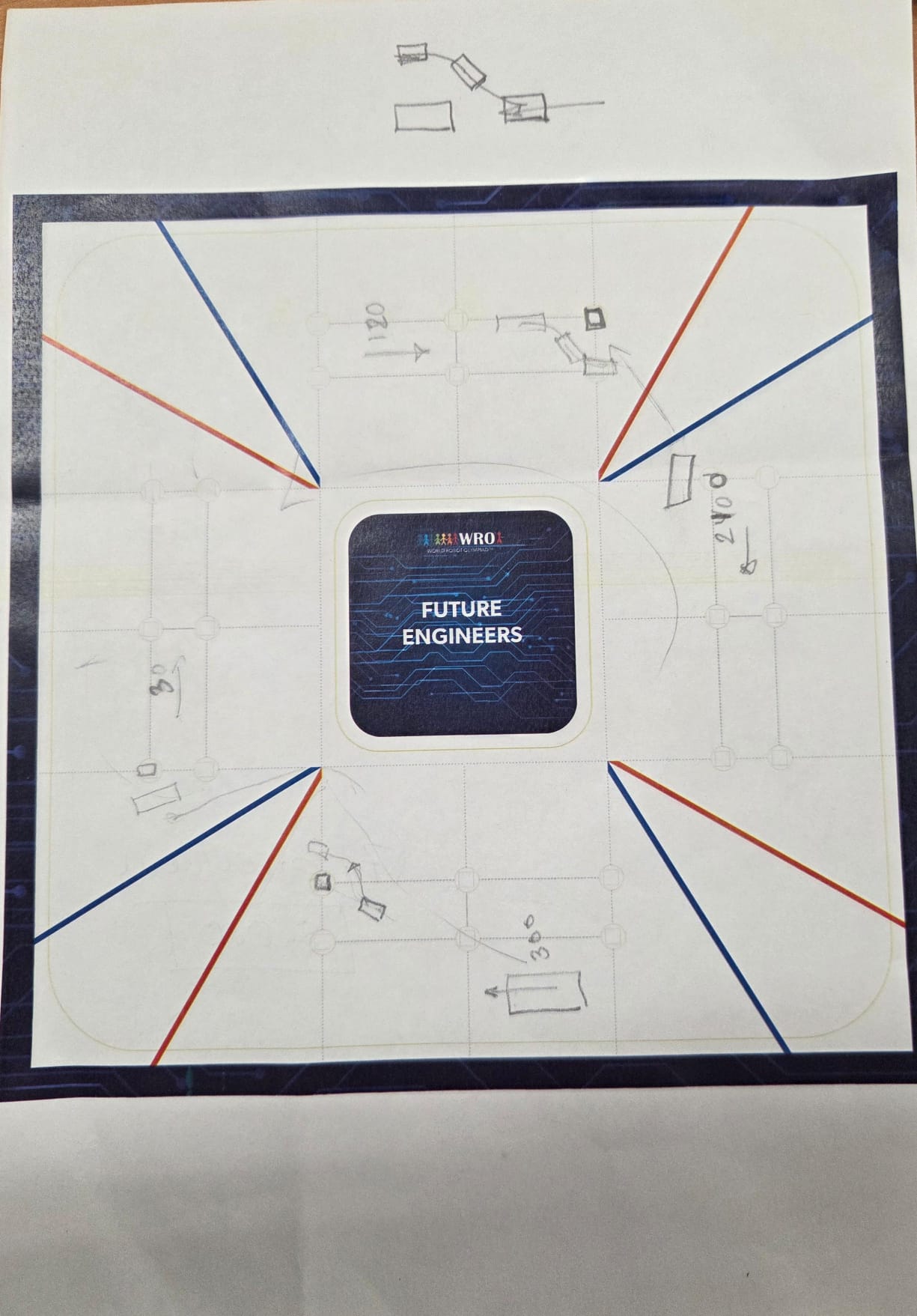
* **08/04/26:** We drew a diagram of how we want to assemble our robot and how we’re going to arrange all the components. We placed the HUSKYLENS at the front to detect colors, positioned a distance sensor on each side so we can measure using any of the four depending on what’s most useful, and placed the batteries under a platform with the wheels (and their respective servomotors), since this saves space and allows us to arrange the board and components more neatly above that platform. On the other hand, we considered different material options for the base, such as wood, plastic (3D printer), and a sheet of foam board we found in class. In the end, we decided that the foam board was the best option, since wood was very difficult for us to work with and would take more time, and 3D printing would also require a significant time investment (which would reduce our ability to test the program) and require us to have a clear understanding of all the component positions (something we weren’t 100% sure of yet). Even so, we decided this would be a temporary solution, and once we had everything figured out, we would make a 3D-printed base.
* **09/04/26:** Using a clamp meter, we measured how much power our robot would consume to determine whether we could use the battery module we had chosen. We found that the HUSKYLENS camera uses between 230 and 420 mA, the Arduino R4 board consumes 100 mA, the HC-SR04 consumes 15 mA, the microservo consumes 200 mA, and the RC servo consumes 700 mA. Therefore, our robot would consume a total of 1215 mA, which would give us just over two hours of runtime. Theoretically, that would be the robot’s total power consumption, but in reality, we measured that the robot consumes 500 mA, so those batteries, which have a capacity of 2600 mAh, should power the robot for more than 5 hours. Meanwhile, we began preparing the wiring for the distance sensors and the servo motors. However, we noticed that the Huskylens module sometimes reboots. We think this is because the Arduino board isn’t able to provide enough power, and we can’t connect it directly to the batteries since the module doesn’t support 8.4 V. While searching for information, we found a type of regulator called the LM7805 that steps down the voltage to 5 V. We’ve decided to use it to power the Huskylens module.
* **10/04/26:** We assembled the robot on the temporary base, trying to pack all the components as tightly as possible. We used hot glue because we had it in the classroom; it bonds strongly to the components we’re using, allows us to attach and detach components easily, and doesn’t damage them. During assembly, we had to cut a hole in the board to mount the 180° servo so it would align with the height of the wheels. Once the entire robot is assembled, we create a program to control it with a joystick and check the maximum and minimum values for each servo. The data we have for the servo are:
* Voltage: 4.8–8.4 V / Imax = 1.2 A / Maximum torque: 14 kg·cm / N = 72 rpm
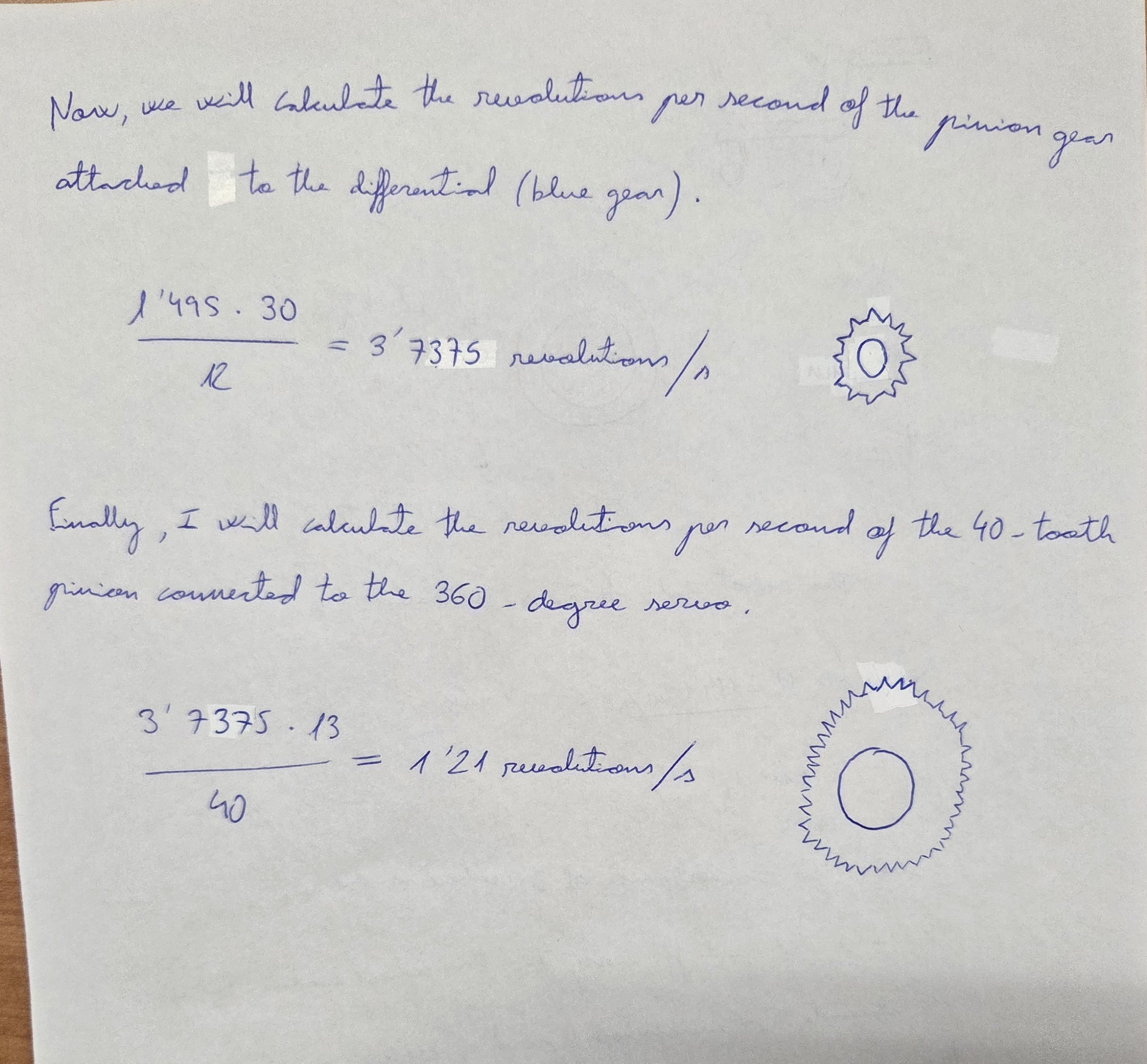
* For the transmission, we have tested various LEGO gears. The differential has a 12/30 reduction ratio, meaning it reduces the speed by a factor of 2.5. Therefore, we need to multiply the speed between the servo and the differential. Through testing, we found that with a 40-tooth gear on the servo and a 13-tooth gear on the differential input, the vehicle achieves an appropriate speed—neither too fast nor too slow.
* Wheel speed calculation: V = 65 × (40/13) × (12/30) = 80 rpm = 1.333 rev/s
* The wheels have a diameter of 43 mm and a circumference L = π × 43 = 135 mm
* The vehicle’s speed is V = 1.3333 × 0.135 = 0.18 m/s. We have verified this data with a stopwatch, and it is correct.
* **13/04/26:** We wrote a program using the distance sensors to make the rear servo move when an object is detected. In doing so, we realized that the library we had always used for these sensors isn’t compatible with the Arduino R4 Mini board, so we looked for another one. The other library we found that was compatible required a common pin to connect all the “triggers” from all the ultrasonic sensors. To do this, we rewired the setup by soldering all the trigger wires from the three sensors together and connecting them to a single pin.
* **14/04/26:** We started creating a basic program to try to navigate around the inside of the parking garage. As we continued testing the programs, we noticed that the robot was moving slower than we’d like, so we decided to increase its speed using a LEGO gear system we have in class. When we incorporated it, we saw that it wasn’t working well because the robot was turning jerkily, so we had to reduce the speed a bit. We thought it was a software issue, so we’re trying to fix it.
* **15/04/26:** We were unable to fix the error by modifying the code, so we decided to change the gear system, this time using only one gear; as a result, it now moves slower than before, but faster than it did at the start. We also added a servo to the HUSKYLENS, as we believe it’s a good idea to use one because we think it has a narrow field of view, and with the servo attached, we’ll be able to rotate the camera and widen the angle. As for the program, the robot manages to turn around, but it makes very sharp turns, and when it gets too close, it crashes into the wall; we’re going to try to fix that.
* **16/04/26:** We continue to plan our programs with the possibility of starting either to the right or to the left in mind, trying to check which way we’re going before leaving the parking lot. We have also added another HC-SR04 sensor at the rear to measure the distance to the parking space divider, making it easier for the program to exit the parking space.
* **17/04/26:** We continued working on the programs, while also exploring options for exiting the parking lot; to do this, we drew inspiration from how participants in previous years had parked. During this process, we came across a robot that used a plastic rod that didn’t interfere with obstacles but allowed it to extend the robot’s length—and, therefore, the length of the parking space. Since we liked this idea, we decided to implement it and devise a parking strategy, taking into account that we now had a greater distance than we initially thought. With that in mind, we decided to create a program.
* **20/04/26:** Since the front wheels keep jerking, we thought the 180-degree servo might be experiencing interference, so we decided to replace it with a better one we already had. It seems to work better, but it still malfunctions quite a bit. As for the program, we managed to get it to exit the parking space; so all that’s left is to have it face the central partition. We also tried using a magnetometer (compass) from class to get a reading of the robot’s position, with the idea of using it for various tasks like exiting the parking lot or making more precise turns. However, upon checking the readings, we saw that the coordinate intervals weren’t consistent and, therefore, didn’t match reality; we decided to order another one.
* **21/04/26:** To try to fix the jerking issue, we installed some laser distance sensors and disabled the ultrasonic sensors. We tested them using a box (as if the box were the center of the board), and it worked quite well most of the time, except for a few instances where it didn’t read the position correctly. Next, we tested it on the official competition board; this time, 70% of the time it didn’t read the curves correctly and didn’t take the right direction. After further testing, we concluded that the problem with these sensors was the reflection of light off the black paint on the walls; therefore, they didn’t solve our initial problem.
* **22/04/26:** We realized that if we connect HUSKYLENS directly to the board, the robot keeps stopping because the Arduino isn't able to power HUSKYLENS properly, causing it to reboot. From now on, we’ll power HUSKYLENS directly from the batteries using a voltage regulator based on the LM7805 circuit, which converts the batteries’ 8.4 volts to 5 volts—enough to power the camera on its own. On the other hand, since we had made so many changes to the robot’s chassis, the base was no longer stable or secure; so we decided it was time to design the final version in 3D. We drew a hand-drawn sketch of where the components would be placed and began designing it in 3D.
* **23/04/26:** We continued working on the chassis design.
* **24/04/26:** We are proceeding to replace all the sensors. We have once again used hot glue for the same reasons: it provides a strong, quick bond, is easy to apply and remove, and does not damage the components. In the process, we encountered several design issues that we resolved manually by removing material with a soldering iron to heat and melt the material into the desired shape, since we didn’t have enough time to redesign and print another part. Even so, we will redesign it in 3D so that the robot is perfectly reproducible. Also, since we were going to change the base, we decided to switch the gear ratio to a larger one to reduce the speed slightly.
* **25/04/26:** We continued assembling the new base and also replaced some of the component cables. We decided to attach the distance sensors to a foam board using hot glue, since hot glue allows us to attach and remove the components easily without damaging them.
* **27/04/26:** We installed the new magnetometer on the robot using a foam board rod to prevent interference issues and added an LCD display so we could view its readings without having to connect to the computer; once this was done, we began testing. The first few tests went well, but after about 10, it stopped working; we also tried the other one that came with the purchase, and the problem was the same as with the first one. We agreed to try one last time, so we ordered one final magnetometer.
* **30/04/26:** We no longer have time to move forward with the challenge, so we began preparing all the documentation.
🏆 May 2026
* **04/05/26:** We are still working on the documentation.
* **19/05/26:** We are working on the final program and retouching the documentation.
* **26/05/26:** We reviewed what happened during the provincial round, as we had several execution errors due to a misinterpretation of the rules. We reread all the rules carefully and revised our strategy. In the free challenge, the robot starts from a specific zone within the region; whereas, in the obstacle challenge, there is the option to start from that same zone or from the parking area. We decided to take advantage of this option to differentiate the type of challenge the robot is facing.
* Free challenge: we start from the required zone, “unpark”, complete the laps, count lines to stop, and “park”. All of this is done primarily using distance sensors, with the exception of line counting (for which we use HUSKYLENS).
* Obstacle Challenge: we start from the parking spot, unpark, drive around while avoiding traffic lights, count lines to stop, find the parking spot, and park. All of this is done primarily using HUSKYLENS.
Once we’ve clarified all this, we get to work. Since the open challenge was almost complete, we redesigned the part about pulling out of the parking spot (which works for us); so all that would be left is counting the turns and parking, but since we don’t have time, we decided to prioritize solving the obstacle challenge.
* **27/05/26:** After testing the HUSKYLENS, we found that I2C communication causes fewer problems than using the serial port. Additionally, we decided to point the HUSKYLENS downward because when we first set it up, it was detecting colors and shapes outside its field of view, causing frequent errors. In light of this, we also positioned it higher to widen its field of view so it could see obstacles from a greater distance and detect them sooner. Additionally, we encountered an issue with the Arduino R4 Minima board (it stopped working); we believe it may have been caused by a power surge, but we’re not certain. Therefore, we decided to use the Arduino R4 board with Wi-Fi/Bluetooth that we had in class, without using its Wi-Fi and Bluetooth modes since that’s not permitted. As for the software, we first tested a program to count laps that we had already created but never got around to testing. After making some changes, we saw that it worked, so we decided to add it; however, as we mentioned yesterday, we decided not to deviate from the plan, to leave the parking part for later, and to focus on the obstacle challenge. Regarding this second challenge, we completed the part about exiting the parking lot and began developing a program that recognizes traffic light colors and avoids them.
* **28/05/26:** Despite our upcoming exams, we’re still dedicating time to finishing and optimizing the program. We’re continuing to work on the obstacle course challenge, but now we’ve decided to also use the object recognition feature since HUSKYLENS was confusing the orange lines with the red traffic lights; once we fixed that, we continued developing the program. On the other hand, the R4 board with Wi-Fi/Bluetooth stopped working at the end of the day; we think the same thing might have happened as with the previous one, but we’re not sure. From now on, we’ll take greater precautions when handling the board, turning it on, turning it off, etc.
* **29/05/26:** We started the day by setting up the new Arduino R4 Mini we bought the day before yesterday, just in case it broke again, and carried on with the obstacle course challenge. We’ve made good progress today as we came to school for a couple of hours this afternoon. As for the obstacle course programme, we’ve managed to get it to go round the right or left depending on the colour of the object. We’ve also decided we should fit a micro-servo to the camera so it can search for objects after passing those it has already seen; we’ve cut out the 3D structure we made for it to fit the servo and ensure it remains at the same height. Due to a lack of time and the number of exams we have, we haven’t had time to continue working on or test the robot much on the circuit; furthermore, we won’t be able to incorporate the latest modification (the servo on the HUSKYLENS support) into GitHub for the reasons mentioned above.
💡 June 2026
* **02/06/26:** Regional competition day. We also asked the organizers if we could make a series of changes we’d come up with, since we felt that the current hardware wasn’t up to the task and we did not know if we were able to make such huge changes on the harware. The Arduino R4 MINIMA has limited programming language capabilities and overall capacity, which prevent us from properly developing the project; and the HC-SR04 and HC-SR04RC ultrasonic sensors give false readings when they aren’t measuring on a flat surface (they don’t allow us to measure at an angle). For this reason, we considered using, on the one hand, an Arduino Q or Raspberry Pi Pico 2 to replace the Arduino R4 MINIMA; and, on the other hand, laser sensors instead of the HC-SR04 and HC-SR04RC. They told us to draft an email to the WRO.
* **08/06/26:** We drafted and sent the email explaining the situation and the changes we want to make.
* **11/06/26:** We received a reply; they’ll accept any changes we make. We looked into it and bought everything we need so it will arrive as soon as possible.
* **15/06/26:** The 3D-designed chassis plate has bent under the weight of all the robot’s components. After evaluating possible modifications to the robot, the final decision was to redesign the plate in 3D to make it thicker so that it can adequately support the weight over time.
* **16/06/26:** We’ve focused on one of the main modifications we’re going to make to the robot: replacing the ultrasonic sensors with laser sensors. Additionally, since we’ve been given the freedom to make as many modifications as we want, we came up with the idea of implementing a LiDAR for a new strategy in which the robot navigates by scanning with the LiDAR. With these two criteria in mind, we evaluated three options:
* TFmini-S.
* TF Luna.
* TFmini Plus.
After evaluating all the options, we decided on the TFmini-S. The TF Luna isn’t powerful enough for this task; it has a shorter range and lower frequency, even though it’s cheaper and uses less power, and the TFmini Plus was too expensive, weighed too much, and consumed more power.
* **17/06/26:** Today we focused on another major modification to the robot: replacing the ARDUINO R4 Minima board with a more powerful one, due to the limitations of the original board. Our two best options are the Arduino Q board and the Raspberry Pi Pico 2. The Arduino Q’s specifications are far superior to those of the Raspberry Pi Pico 2 (more power, built-in microprocessor and microcontroller, more RAM…), so we’re going to choose that one.
* **18/06/26:** Since the idea of adding a battery holder to power various components—and thus prevent interference between them—yielded excellent results, we designed the holder using 3D printing because it is more durable than foam board. We also added stickers from the project’s various sponsors.
* **23/06/26:** The distance sensors have arrived. We ran tests using a simple program to calibrate the measurements. We saved the data for the programming phase.
* **24/06/26:** The Arduino Q board has arrived. When we tested it, we discovered that we’re going to face significant challenges when it comes to programming, since the microprocessor and the microcontroller—both integrated onto the same board—are programmed separately. Therefore, we’ll need to write two separate programs. After weighing the pros and cons of this approach, we’ve decided there isn’t enough time for that and that we’ll try the board we evaluated earlier, the Raspberry Pi Pico 2.
* **25/06/26:** The final decision regarding the board and its programming has been the Raspberry Pi Pico 2. We will program it in Visual Studio Code, a programming environment we are familiar with from various projects throughout the school year. To do this, we need to learn the Python language, but we believe we have time for that.
* **26/06/26:** Since we don’t have the Raspberry Pi Pico 2 yet, we’ve assembled all the components on the new 3D base. In the meantime, we’re continuing to study Python so we’ll be ready when it’s time to program.
* **29/06/26:** We’ve established a new strategy to tackle the challenge based on our experience in the regional competition:
* First: The robot begins in a loop where the lights are flashing until the push button is pressed. When the button is pressed, the robot sweeps forward. If it doesn’t detect anything at a certain distance (we’ll figure that out later), the robot determines it’s in the free challenge; if it detects an obstacle at that distance, then it determines it’s in the obstacle challenge.
* Free Challenge: The robot moves backward until it detects the wall with the rear sensor. If this takes too long, it might be a good idea to add a color sensor to detect the line; this way, it could also determine whether the direction is clockwise or counterclockwise. Once it knows the direction and has detected the wall, it approaches the interior partition and circles it while maintaining a certain distance from the partition’s walls. At the same time, it counts the lines using the HUSKYLENS (it would be even easier with the color sensor). When the counter reaches a specific value, the robot stops in the quadrant from which it started.
* Obstacle Challenge: The robot exits the parking garage using the following maneuver: it moves backward to a certain distance from one of the garage walls, then turns completely to one side to exit. From there, whenever the HUSKYLENS detects an obstacle, it approaches it: if the obstacle is green, it goes around it on the left; if it’s red, on the right. The HUSKYLENS also continues counting the lines to stop the robot in the corresponding quadrant.
* **30/06/26:** We’ve finally decided to incorporate a TCS34725 color sensor. We’ve used this sensor before in high school, which is why we chose it. We plan to wrap it in a layer of EVA foam to prevent confusion caused by light reflection and thus obtain more accurate readings. We’ll use this sensor to count the lines in both challenges.
🔩 July 2026
* **02/07/26:** The Raspberry Pi Pico 2 arrived today. First, we installed the firmware so we could upload code from VS Code. Since this is a different board from the one we’ve been using, we’re going to start with the basics: getting the robot to follow the wall, measuring distances with the sensors...
* **23/07/26:** Today we started with the basics: getting to know the board and seeing how it responds. The main problem is that we’re moving more slowly because we have to program in Python.
* **24/07/26:** Today we continued conducting basic tests that will help us when we create our versions of the final program. After that, we made significant progress: we got the robot to follow the wall by controlling the distance between the robot and the wall at a constant speed. In other words, we’ve almost completed the obstacle-free challenge; we still need to figure out how to track the number of laps we complete and how to start from the starting zone. We’ve also noticed the difference between the ultrasonic sensors we had before and the laser sensors we have now; the laser sensors are much more precise, and they can also measure at an angle, unlike the ultrasonic ones.
* **28/07/26:** We decided to finish the first test first (the challenge with no obstacles or parking). Once we made that decision, we continued thinking about how to count the laps we complete without using the HUSKYLENS, since counting the lines wasn’t very accurate. By late afternoon, we decided that a color sensor would be the best solution—one that detects the lines as the robot passes over them and distinguishes them by color. That way, the robot can keep track of how many laps it has completed and stop at the correct spot. We searched various online stores for color sensors that would meet our needs and have placed an order. In the meantime, we’re considering different strategies so that, from the starting point, the robot knows which direction to go and how to approach the wall in order to follow it and complete the three laps. Previously, we would back up until the side sensor could no longer detect the wall before the robot began to turn; this time, the robot will move backward, and depending on the color of the line it sees first, it will approach the wall in one way or another, depending on which direction it needs to turn.
* **29/07/26:** The color sensor arrived today, and we ran some tests with it. To start with, we calibrated it, and now when it passes over the orange and blue lines, it tells us what color each one is. However, once we incorporated the color sensor into the program, we noticed that it doesn’t always detect them correctly or sometimes gets the colors mixed up.
* **30/07/26:** As soon as we arrived at school, we picked up where we left off yesterday; we reviewed the part of the algorithm involving the color sensor and made some modifications to refine it. We ended the afternoon with our first perfect run—the robot is now able to complete three laps and stop in the correct zone regardless of the direction it takes (clockwise or counterclockwise).
* **31/07/26:** Starting today, we’ll begin the second challenge (the obstacle challenge). We believe that this time we can do it right thanks to the hardware improvements with the light and laser sensors. Today, we only managed to get the robot to recognize that it’s in the obstacle challenge by measuring with the distance sensor and to exit the parking lot while orienting itself in the best way possible so it can easily see the obstacles.
⏳ August 2026
* **03/08/26:** We tested the program we hadn't tested the day before and realized that the right TOF400F can't detect the interior wall because it's so far away. After thinking about how we could solve this, we concluded that the best approach would be to use both TOF400F sensors (since we have one on each side) to navigate down the center of the hallway. Once we tested this, the same problem arose, so the only viable solution we found was the following: search for and avoid obstacles one by one, using the TF-mini-S to determine which one is closest in case the HUSKYLENS detects more than one, and aligning the chassis with the camera to center the obstacle. To do this, we decided to perform 90° scans with the front servo (HUSKYLENS + TF-mini-S), slowing down the robot’s speed to facilitate data collection. In addition, we took the opportunity to change our initial strategy for determining the orientation of the challenge; this time, we used the TOF400F sensors instead of the TF-mini-S, as we believe this will save us some time.
Since we had slowed down the robot, we retested the free challenge to verify that there were no changes in its performance. During testing, we realized that the line counting was failing again, so we decided to use RGB values instead of brightness levels to identify the lines. This solved the problem.
Before finishing, we decided to break down main.py into subprograms; since the program was too long and made it difficult to read, this way we can find what we're looking for more easily.
* **04/08/26:** Today we started testing both challenges to get a clear idea of how we’re doing. During these tests, the robot had several issues recognizing which challenge it was on, and we believe the TF-mini-S is providing erroneous readings, so we decided to implement redundant checks using the side-mounted TOF400F sensors. This allowed us to resolve the issue, so we’re continuing with the open challenge. We’ve devised the following strategy, taking into account the three possible scenarios that could arise once the robot exits the parking lot:
* 1. The robot does not see any obstacles; in this case, it should perform a 90° scan. If it sees nothing, it should perform an 180° scan (to expand the field of view), and if it still sees nothing, it should head toward where the TF-mini-S has detected a greater distance, thereby attempting to find the aisle.
* 2. The robot detects an obstacle; in this case, the robot should move toward it until it is 12 cm away (which we have estimated to be sufficient for a successful dodge) and then dodge it on the correct side, using the corresponding side sensor to verify that the maneuver was performed correctly.
* 3. The robot detects two obstacles; in this final case, we calculate the area of both objects (using the x and y data provided by HUSKYLENS), and once we know which one is closer, we implement the strategy from the previous case. In addition, if the robot detects another obstacle while avoiding one, we believe it should head directly toward it. We write the code.
* **05/08/26:** We tested yesterday’s code, analyzing it step by step. Clearly, it isn’t working well for us—since it targets the first block it sees, it performs very abrupt scans until it dodges it, when it should lock onto the block and move toward it without scanning. We managed to fix this, which is a big improvement; however, we’re still running into problems. We decided to continue tomorrow.
* **06/08/26:** The problem we identified yesterday is this: when the block is very close, the robot doesn’t have time to dodge it and ends up bumping into it. After brainstorming, we concluded that if we keep the block centered with HUSKYLENS at all times, we could track its location during the dodge and check the distance to it to avoid getting too close (if the distance is too low, the robot should move away); once it has dodged the block, the front servo would return to its forward position to continue with the challenge. We also decided to increase the distance at which the robot begins to avoid the block from 12 to 15 cm to allow for more room to maneuver. After making several changes to the program, it works better but not as well as we’d like; still, we decided to leave it as is for now. On another note, we’ve started researching the magnetometer (which we had previously purchased for the provincial and regional rounds but ultimately didn’t use), since we believe it could be quite useful for navigation purposes.
* **11/08/26:** Since we were considering the idea of using the magnetometer, we realized we could use it for both the obstacle challenge and the free challenge. So, we started brainstorming ideas and decided to use it to align the robot with the direction of the street it was on. We would do this when the robot detected an orange line using the color sensor. When that happened, it would indicate that the robot had turned onto the next street and would therefore need to follow the new direction of that street. After testing it in both directions, we saw that everything was working correctly and decided to focus on the obstacle challenge.
* **12/08/26:** We looked into the possibility of replacing the Husky Lens camera with one that had a wider field of view, but when we tried it, we realized it had too wide a field of view—it could see most of the objects in the classroom, but they appeared distorted, and the obstacles on the track looked too small. Therefore, we decided to keep the Husky Lens camera, even though it had a narrower field of view.
* **13/08/26:** We tried completing the obstacle challenge without using the magnetometer, since we noticed it gives errors when we’re in a classroom with metal objects nearby. When trying to avoid three blocks, it successfully navigated the first two, but failed to clear the last one. We think this was because, after avoiding the second block, it ended up facing the outer wall, and when it finally turned, the camera didn’t detect the object and it drove right past it. Because of this, we’re going to try using the magnetometer again.
* **14/08/26:** Today we revisited the idea of using the magnetometer in the obstacle course test and decided to have it scan the direction of each lane on the circuit at the start of the challenge. That way, if—while dodging an obstacle—it doesn’t find another one to avoid, as happened the previous day, it will align itself with the lane it’s in to continue searching for obstacles, just as we did in the free challenge.
* **17/08/26:** Today, after testing the latest program we had, we realized that when the camera detected two obstacles and had to decide which one to pass first—since we told it that the one with the larger surface area should be passed first—the camera determined that the obstacle that should have been passed first actually had a smaller surface area than the one that should have been passed second, and it completely ignored the closer one. Therefore, we’ve decided that this time, instead of using surface area as a guide, we’ll use the Y-coordinate of the objects. Additionally, we think that after dodging an obstacle, the robot should perform an 180° scan, and while using the compass, it should also perform a slightly smaller scan—about 120°—to prevent it from missing any obstacles. We’ve also noticed that it gets quite close to the circuit walls. To fix this, we’re going to monitor the lateral distances using the TFmini-S. Finally, we’ve realized that when dodging a red object, it also gets quite close to it; therefore, we’re going to have the robot correct this by increasing the turning angle of the wheels so as not to displace the block.
* **18/08/26:** After testing yesterday’s program, we noticed that sometimes the robot keeps facing the outer wall, and when it scans, it fails to see the next block and skips over it. Therefore, since we couldn’t increase the angle any further, we decided to reduce the robot’s speed so that it doesn’t skip any obstacles while scanning. We’ve also noticed that when the robot moves backward, it only does so when approaching another robot instead of also using it to align itself; as a result, it passes some blocks incorrectly because it isn’t positioned properly, but we’ll leave this problem for tomorrow.
* **19/08/26:** We’ve identified several issues after running the latest program. The first one is that whenever it approaches an obstacle—regardless of whether it detects it as being too close or not—the robot backs up. This is because it moves toward the block too quickly, and when it stops, it ends up too close to the obstacle and ultimately has to back up. However, it doesn’t back up far enough, so it ends up avoiding some blocks on the wrong side. We’re going to modify it so that the robot backs up until it’s about 18 cm from the block and can avoid it perfectly, after a reading from the TFmini-S while the HuskyLens camera screen has the block centered. While testing the modified program, we’ve noticed that sometimes, when trying to align itself with the direction of the street and not seeing anything, it heads toward the outer wall and pushes against it.
* **20/08/26:** We realized that the problem we encountered yesterday—where the robot was moving toward the outer wall and pushing against it, is due to the fact that when it exits a block, we’ve programmed it to move slowly until it’s completely out of the block, while the compass instructs the robot to turn right. As it approaches the wall, it tries to move away in the opposite direction, which is why the robot gets stuck. So we’re going to make it so that when the course deviation is too large—exceeding 45°—the robot reduces its speed even more than it would for a smaller deviation. And to prevent it from getting stuck, we’ll have the robot turn while backing up to correct its position when it’s too close to the wall and get back on course. We’ve also noticed that sometimes, when clearing an obstacle with the left TOF400F, it takes too long to realize that it has already cleared it. So now we’re going to use the TFmini-S to handle this.
* **21/08/26:** We spent the day refining our documentation on GitHub to try to achieve the highest score on each of the competition’s documentation requirements.
* **24/08/26:** We’ve realized something. After running the program and while it was following the course, we noticed that our robot’s wheels were slipping on the track, causing the robot to drift slightly as it moved along the path. We believe this is because the back of the robot carries significantly more weight than the front. That’s why we’ve decided the best option would be to add more weight to the front using lead so the wheels don’t slip. We’ve also noticed that when trying to avoid a block—and while it uses the TFmini-S to determine whether it has passed it or not—sometimes it does so correctly, but other times it ends up too far away. We could solve this by avoiding the blocks based on time.
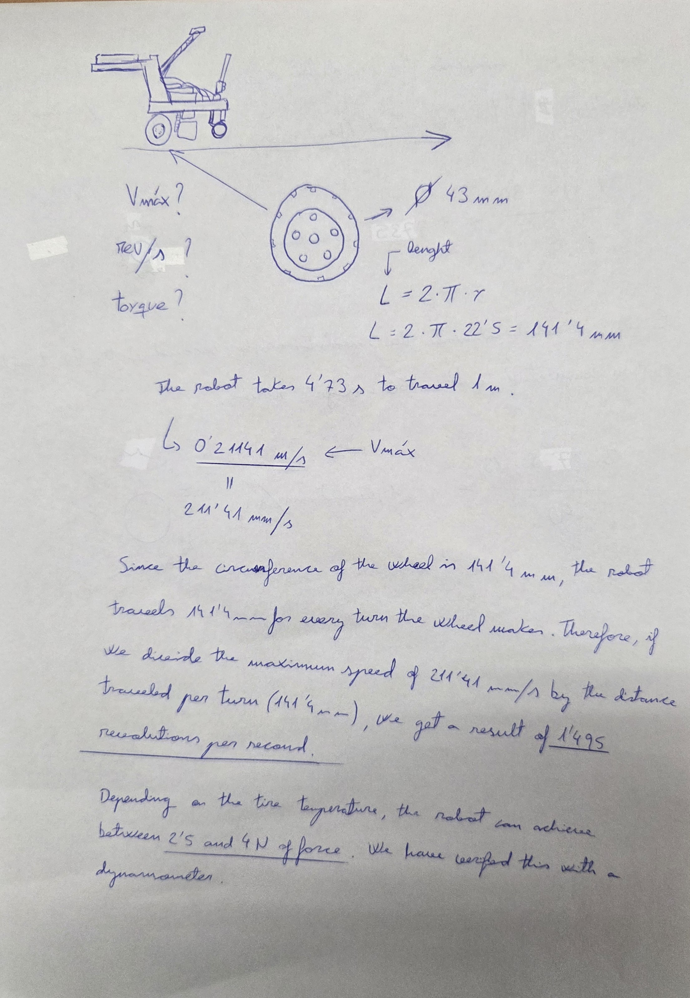
* **25/08/26:** By placing the lead weight at the front, we have managed to stop the robot’s front wheels from skidding. However, we have noticed that we are still experiencing the same problems we had some time ago. Firstly, when approaching a block, it continues to reverse, even when it is not necessary. Secondly, when passing a block, sometimes it does so correctly and other times it carries on forwards, knocking the obstacle over. We believe this is because, when it is about to avoid an object, the TFmini-S servo and the Husky Lens should instantly move to 90° on the corresponding side once it has passed the obstacle, but it does not do so. To solve both problems, we are going to make it turn right first, move straight ahead for a short while, turn left and then move straight ahead again. The third problem we have observed is that when it aligns with a pillar, the direction straightens out gradually, and this costs us quite a bit of time. That is why we have decided it should continue to do so, but at a slightly faster pace so as not to lose so much time. Finally, we’ve carried out the necessary calculations to determine: the torque, the revolutions per minute and the maximum speed the robot reaches.
* **26/08/26:** Today we carried out a test with three red blocks in a row. At the second obstacle, as soon as it had finished going round it and just before checking whether it had passed it, the robot performed a sweep to check for further blocks, rather than doing so without moving the servo. As a result, the robot detected this second obstacle again, avoided it once more, and has now moved on to the third block. The solution to this problem is that, instead of simply using the Husky Lens to check for an obstacle, we’ll use the TFmini-S to determine whether it’s more than 30 cm away, to ensure it isn’t avoiding the same obstacle again. Furthermore, we’ve noticed that sometimes, during the initial scan, it detects the car park wall and mistakes it for a block. So we’ve added a small straight-line movement to prevent this confusion.
* **27/08/26:** We started by focusing on the problem of the robot getting too close to the wall. What we’ve done is make it check the distance to the wall on the left and on the right; if either is less than 30 cm, it means it’s close to a wall and must therefore correct its course by adding a value to the compass heading. However, we’ve found that when implementing yesterday’s modification, we’ve uncovered a new problem. After finishing going round the obstacle, if it spots an object before checking whether it has already passed it or not, it heads straight for it. The problem is that sometimes it spots an obstacle in the distance and ignores the one that is closer. Therefore, we are going to programme it so that, upon finishing going round the block, it checks whether there is an object in front of it, but by scanning 30° to each side. After sorting out this problem, we’ve spotted another one. We’ve now realised that it no longer backs up if it’s very close to a block in order to avoid it more effectively. Instead, it ploughs straight through it and ends up facing the same object again. We’ve now programmed it to back up when the object is at a distance of 25 cm or less. But we’ll leave that to sort out tomorrow.
* **28/08/26:** Today we have once again focused on improving our documentation.
* **31/08/26:** Let’s pick up where we left off the other day. We’ve now identified why the robot was previously knocking the block over: it’s because we’ve programmed it to start dodging when the object is 15 cm away, but what actually happens is that it starts dodging when it’s 5 cm away, which is why it ends up knocking it over. This is because, immediately after taking the reading, the camera has to be repositioned, the LED switched on and other tasks carried out within the same loop; consequently, until it has completed all of these, it does not detect that it has reached the block or start to swerve. As a solution, we’ve programmed it to check whether it has reached the block immediately after sending the reading, and only then carry out everything else. And now it only reverses in extreme cases where it is 7 cm or less away.
* **01/09/26:** We managed to get our robot to complete three full laps of the circuit in the obstacle challenge, starting from the parking area, but we were unable to return and park in the parking area, and we had to remove the parking area before completing the first lap as we spotted a problem. Due to the quality of the Husky Lens, it recognises the parking area as a red block. We have therefore decided to change our strategy. We will now start the obstacle challenge without the parking area.
* **02/09/26:** Hemos empezado a lanzar ideas para ver cómo resolvemos la decisión inicial, la que hace que sepa si está en reto libre o con obstáculos y si está girando a sentido horario o antihorario. Hemos llegado a la conclusión de que el robot debería ir marcha atrás y, tras ello, que la Husky Lens mire hacia la izquierda y hacia la derecha para ver si hay bloques. Si los encuentra, para saber hacia qué sentido está, miraríamos si la coordenada X del objeto es mayor de 160, giraría en sentido horario, y si por lo contrario es menor de 160, giraría en sentido antihorario. Si aun así no los ve, tiene que ir hacia delante hasta sobrepasar la esquina y hacer la primera curva. Si no ve ningún bloque significa que está en el reto libre y, si por lo contrario ve alguno, está en el reto con obstáculos.
* **03/09/26:** Today we’ve come up with an idea regarding the robot’s speed, as the motor isn’t running as fast as we’d like. The idea is to fit a larger gear than the one we currently have. We’d fit a 50-tooth gear so that the robot can complete the challenges more quickly. We’ve also decided to remove the edges from our base so that it doesn’t knock over any blocks or hit the walls, although we’re not sure when we’ll implement this change. Also, whilst running the programme for the obstacle challenge, we decided to remove the feature where it checks for walls every now and then to avoid collisions, as it sometimes gets confused by this. Finally, we’ve noticed that in the latest tests our robot confuses the orange lines with red blocks, but we’ll look into this further tomorrow.
* **04/09/26:** As we mentioned yesterday, our camera was mistaking the orange lines on the circuit for red blocks and ended up crashing into the wall. Well, as soon as we arrived today, we tried to track down the error and discovered that it is due to the lighting in the classroom where we are working; when we focused on the areas where it was getting confused, using the torches on our phones, it worked perfectly. However, we are still going to try to fix the problem by making smaller sweeps around the bends so that it does not detect the orange line as a red block.
### 4. 🛠️ Mechanical Design
This section is dedicated to the robot’s mechanical components: the list of parts used in its construction and the 3D-printed parts we designed and printed.
4.1 First version - Components and 3D designs
Here is a also a list of all components we used; including an image, their specific function in the robot, and a purchase link:
| Component | Quantity | Image | Function | Purchase link |
| :---: | :---: | :---: | :---: | :---: |
| HC-SR04RC | 2 | 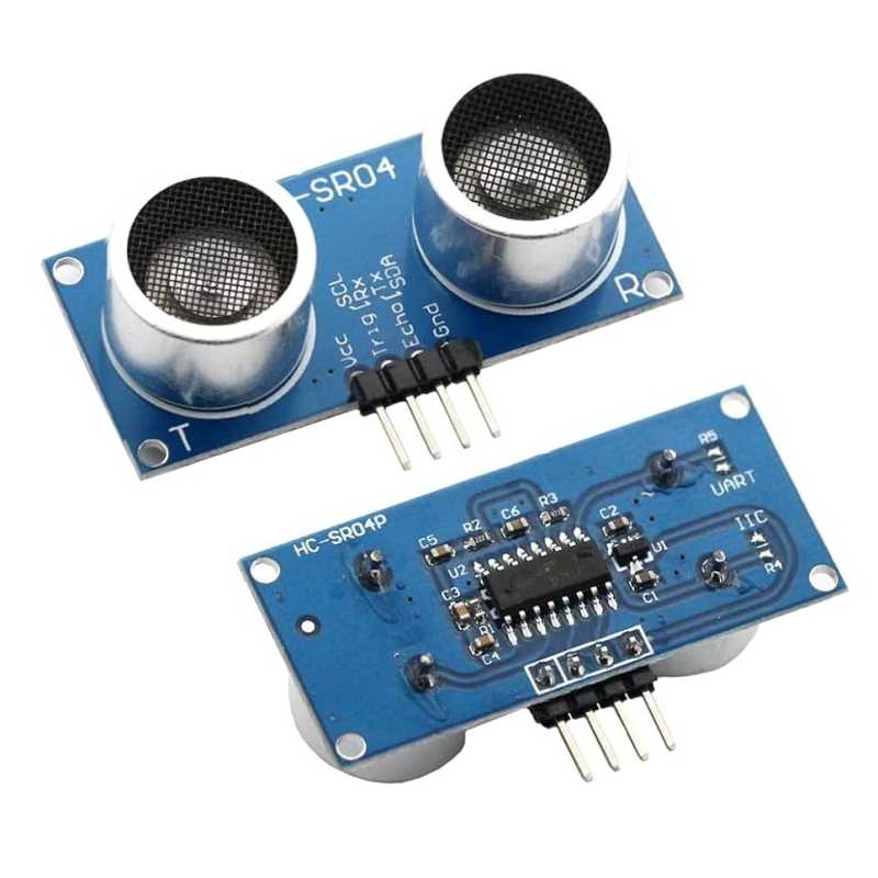 | Measure distances | 🛒 Shop |
| HC-SR04 | 2 |
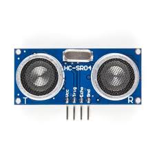 | Measure distances | 🛒 Shop |
| Arduino R4 MINIMA | 1 |
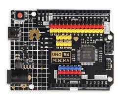 | Robot controller | 🛒 Shop |
| Quick-connect panel | 1 |
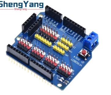 | It allows us to connect all the sensors and servos to the Arduino thanks to all the pins it has | 🛒 Shop |
| Battery support | 1 |
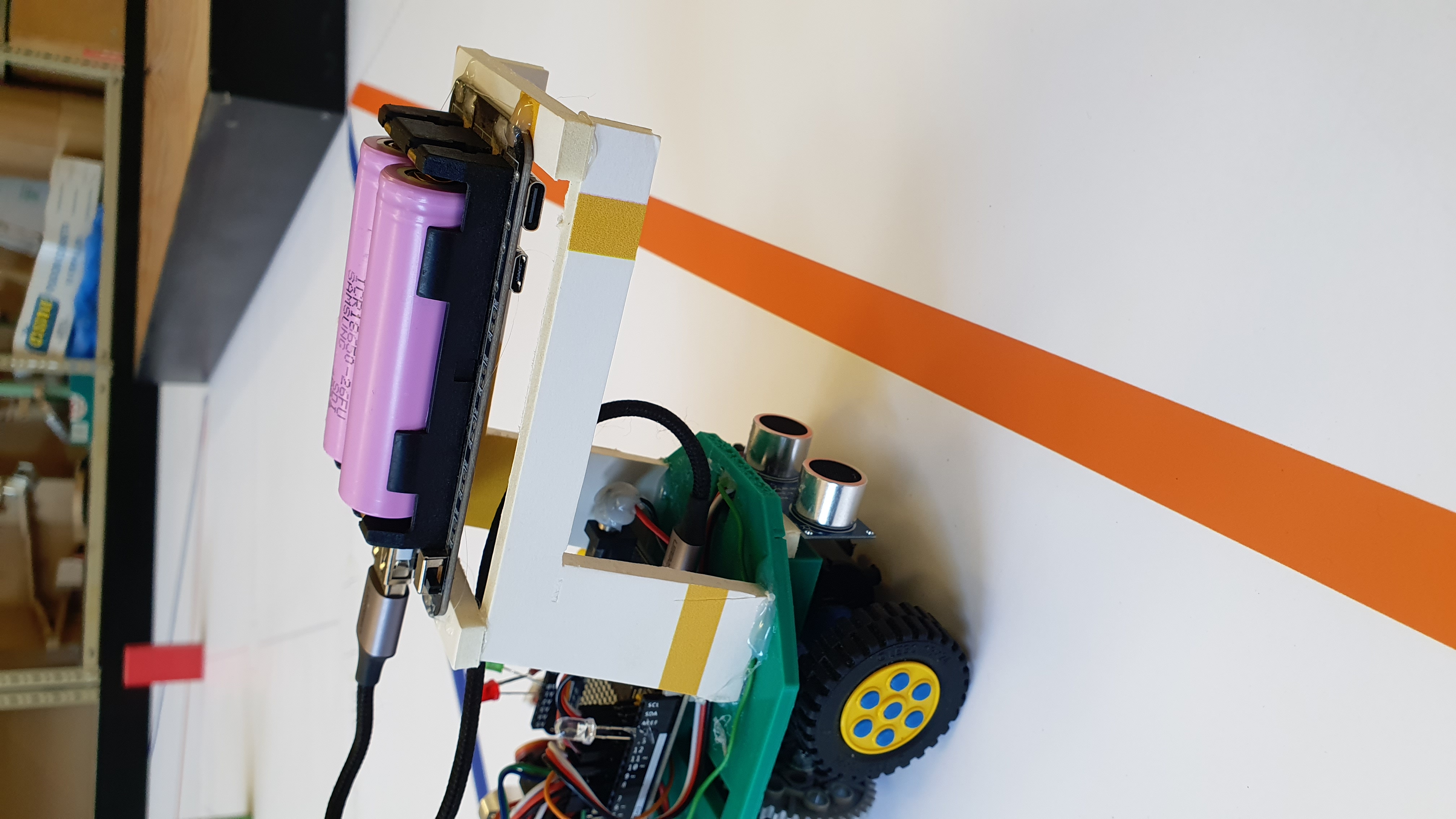 | Is the support of the second battery | We made it in class using a kind of cardboard and hot glue|
| Chasis in 3D | 1 |
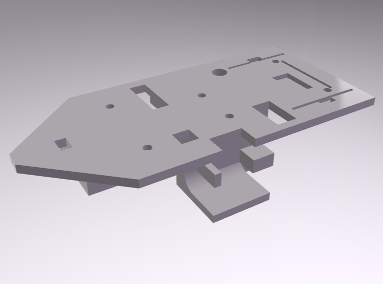 | Skeleton of the robot | [`📥Download`](models/CHASSIS.stl) |
4.2 Second version - Components and 3D designs
Here is a list of all components we used, including an image, their specific function in the robot, and a purchase link:
| Component | Quantity | Preview | Main Function | Purchase link |
| :---: | :---: | :---: | :---: | :---: |
| SPT5632-360 | 1 | 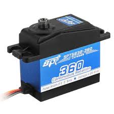 | Robot mobility | 🛒 Shop |
| MS18 | 1 |
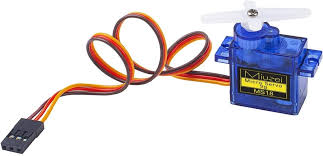 | Robot direction system | 🛒 Shop |
| TFmini-S | 1 |
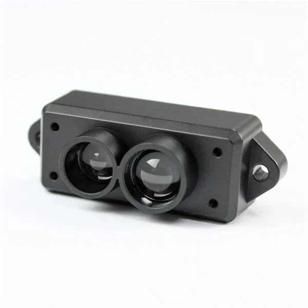 | Measure distances | 🛒 Shop |
| T0F400F | 2 |
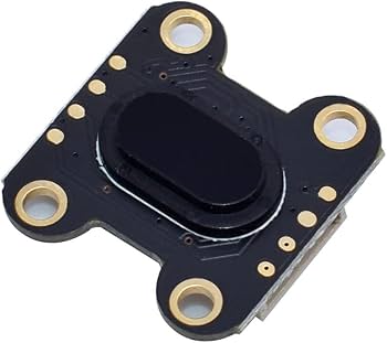 | Measure distances | 🛒 Shop |
| LED | 2 |
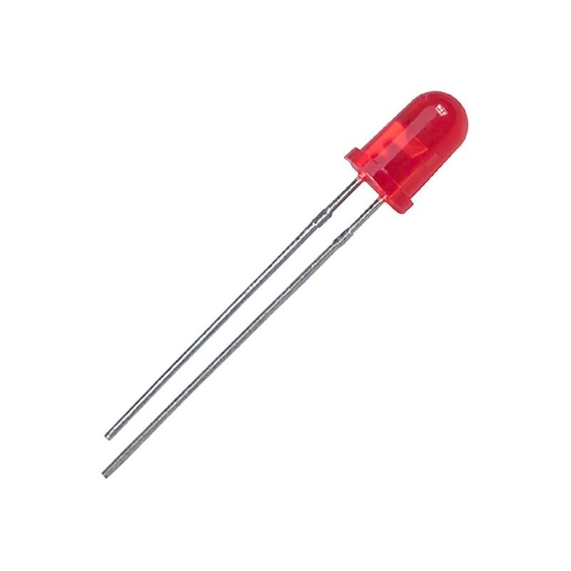 | Checkpoints | 🛒 Shop |
| HUSKYLENS | 1 |
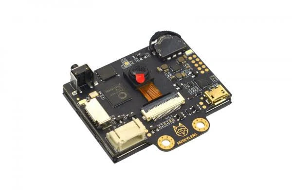 | Object detection | 🛒 Shop |
| Raspberry pi pico 2 rp2350 | 1 |
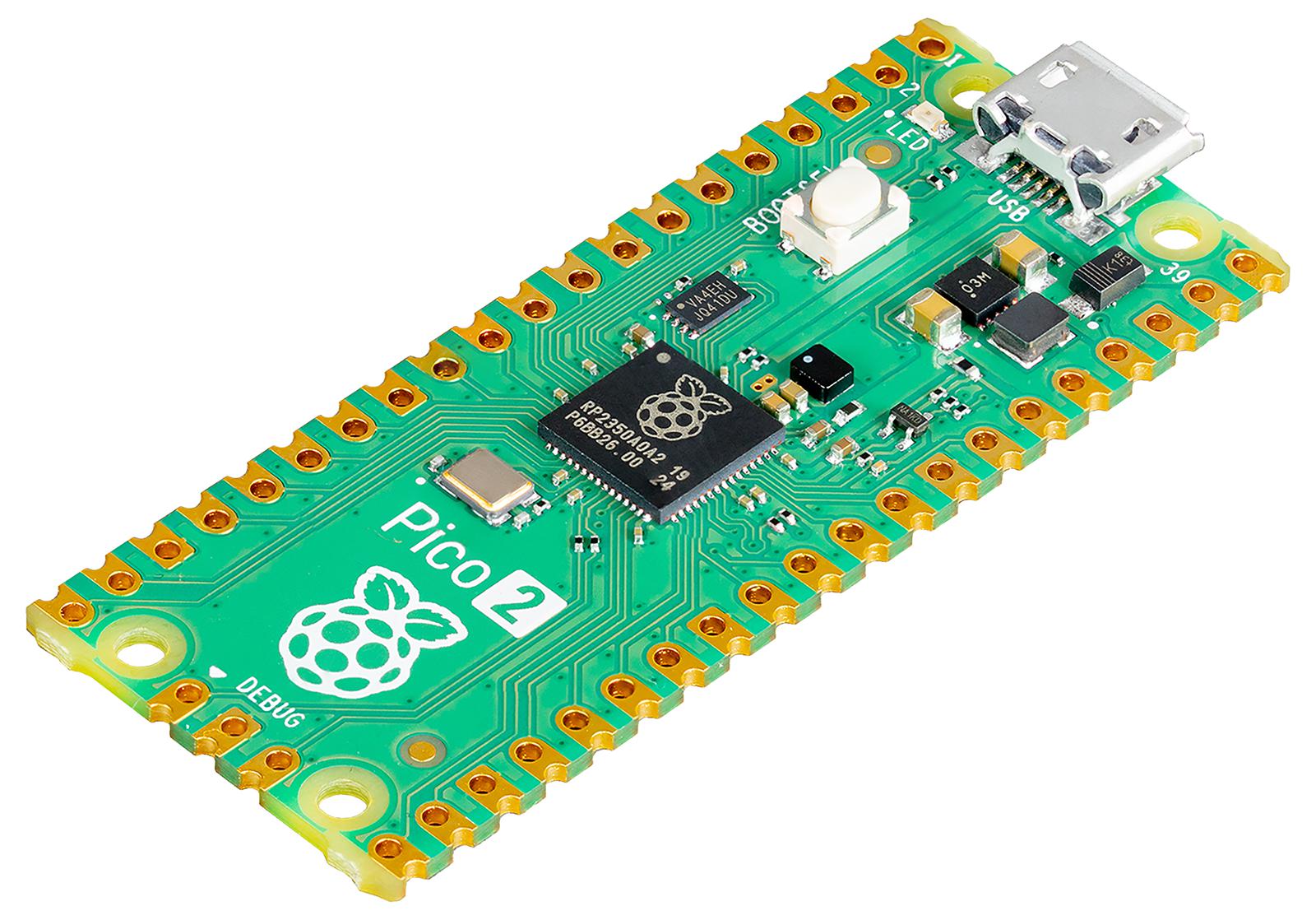 | Robot controller | 🛒 Shop |
| KS3017 Keyestudio Raspberry Pico IO Shield | 1 |
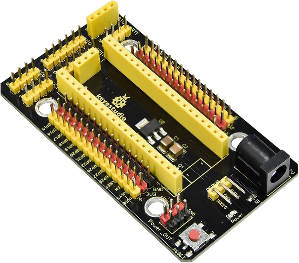 | Conexions | 🛒 Shop |
| 10 DOF IMU sensor (L3GD20 - gyroscope) | 1 |
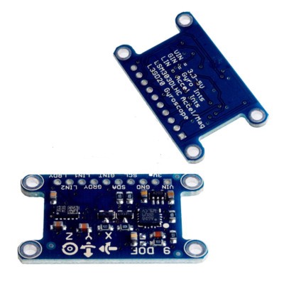 | Robot orientation | 🛒 Shop |
| TCS34725 RGB sensor | 1 |
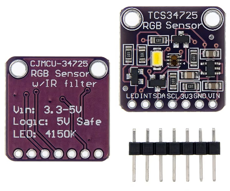 | Lines detection | 🛒 Shop |
| Rocker Switch | 1 |
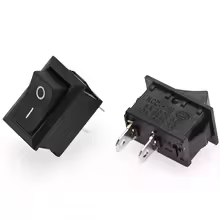 | Power on and off robot switch | 🛒 Shop |
| Pull down button | 1 |
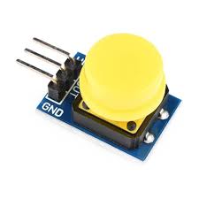 | Starter robot program button | 🛒 Shop |
| Samsung battery 2600mAh | 4 |
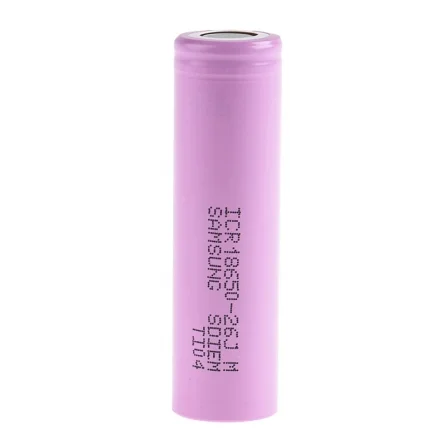 | Batteries | 🛒 Shop |
| Lego wheels 30,4x14 | 2 |
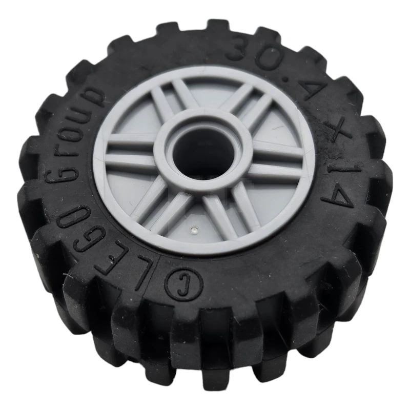 | Directional wheels | 🛒 Shop |
| Lego wheels 13x24 | 2 |
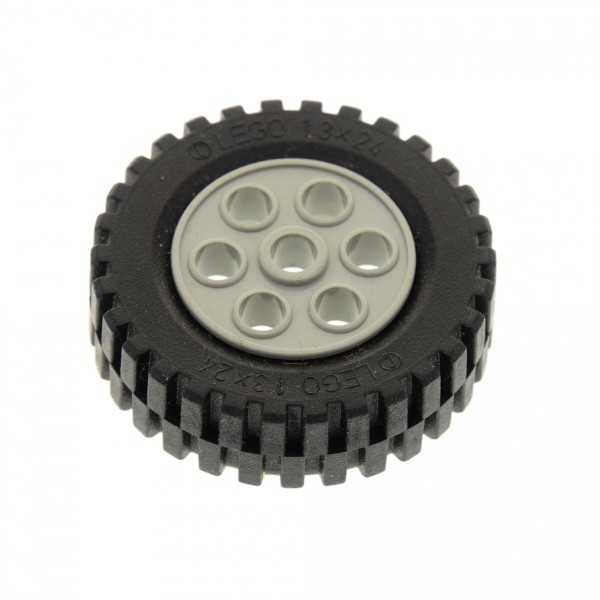 | Drive wheels | 🛒 Shop |
| Servo arm | 1 |
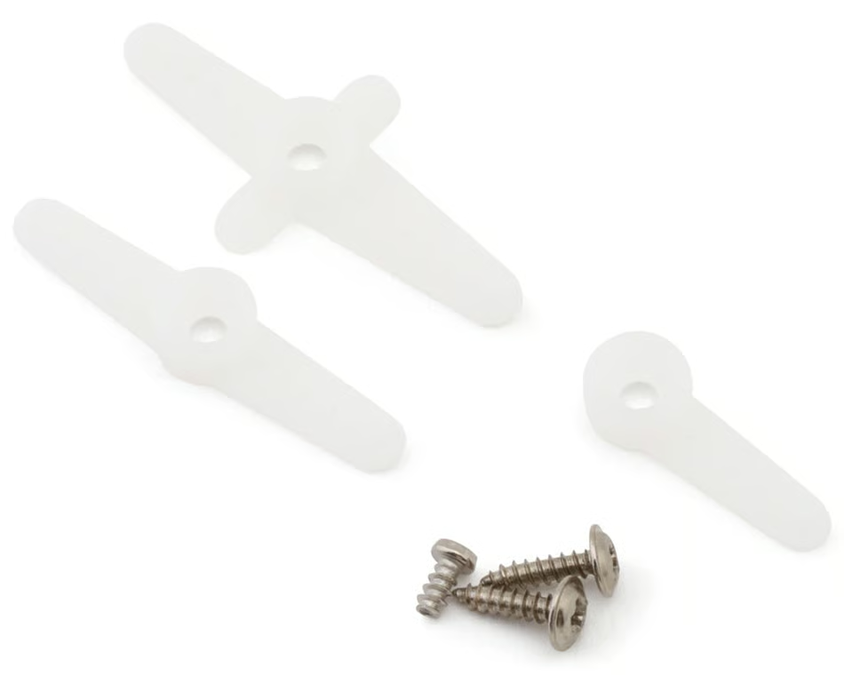 | Servo direction arm | 🛒 Shop |
| Gear teeth Lego 4285634 | 1 |
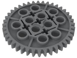 | Gear teeth transmission | 🛒 Shop|
| Lego structure piece 4495931 | 3 |
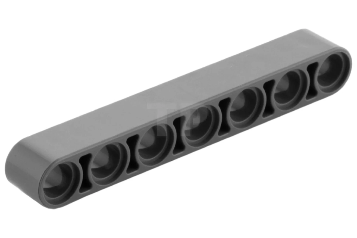 | Maintain direction structure | 🛒 Shop |
| Lego structure piece 4210686 | 3 |
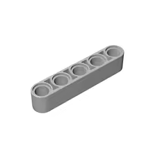 | Connect directional wheels and connect them with the structure | 🛒 Shop |
| Lego piece 4514554 (3 modules) | 3 |
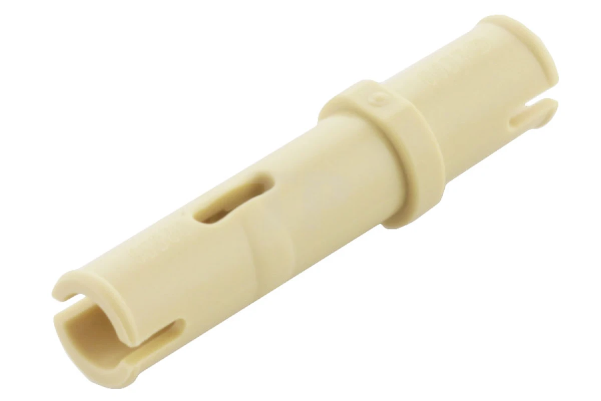 | Connect the directional | 🛒 Shop |
| Lego piece 4514553 (3 modules) | 4 |
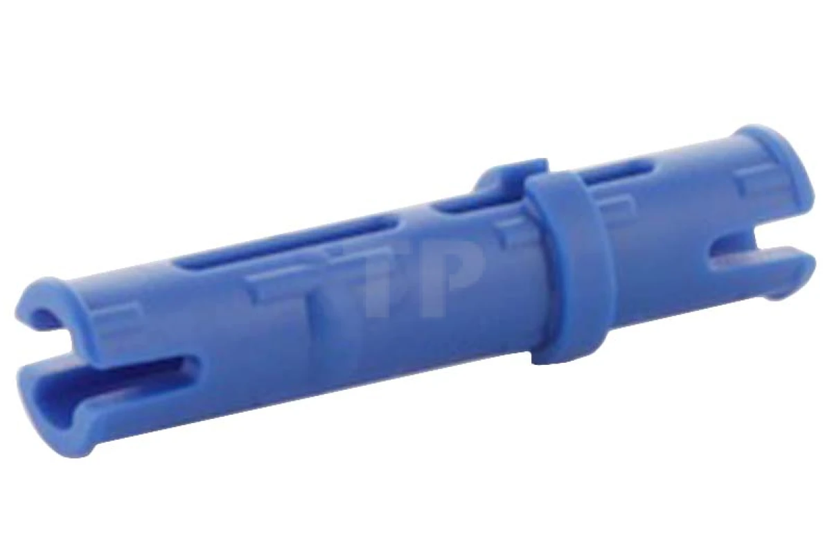 | Connect the directional structure and connect it with chassis | 🛒 Shop |
| Lego piece 4211807 (2 modules) | 2 |
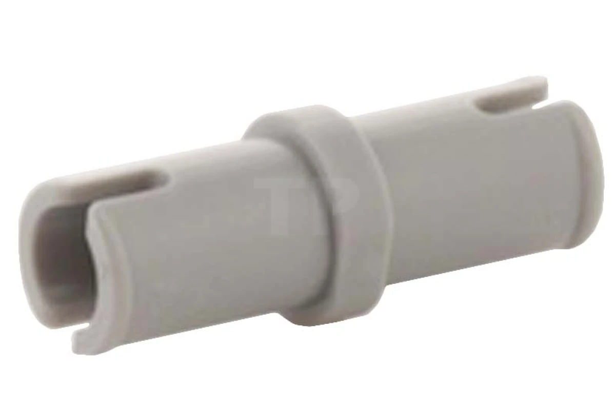 | Connect the directional structure | 🛒 Shop |
| Lego piece 4495931 (2 modules) | 1 |
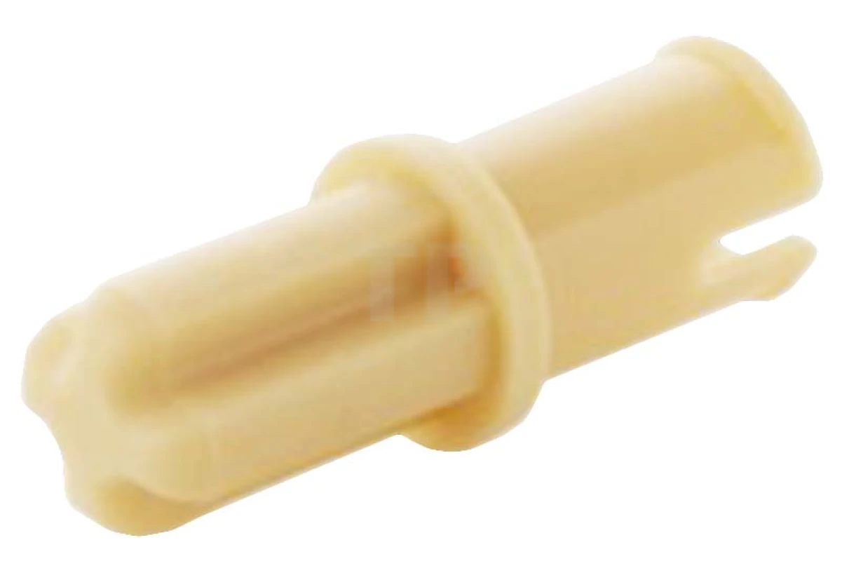 | Connect directional structure | 🛒 Shop |
| Lego piece 4560175 | 1 |
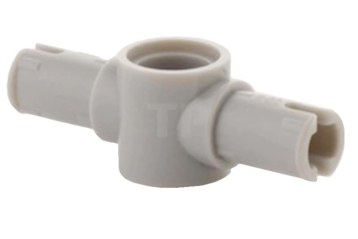 | Connect directional structure | 🛒 Shop |
| Lego piece 4107767 | 2 |
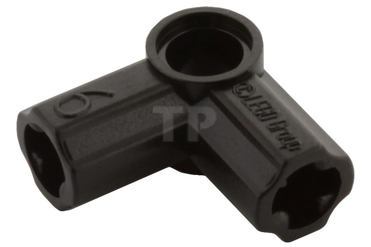 | Connect directional wheels with directional structure | 🛒 Shop |
| Lego piece 4107085 | 2 |
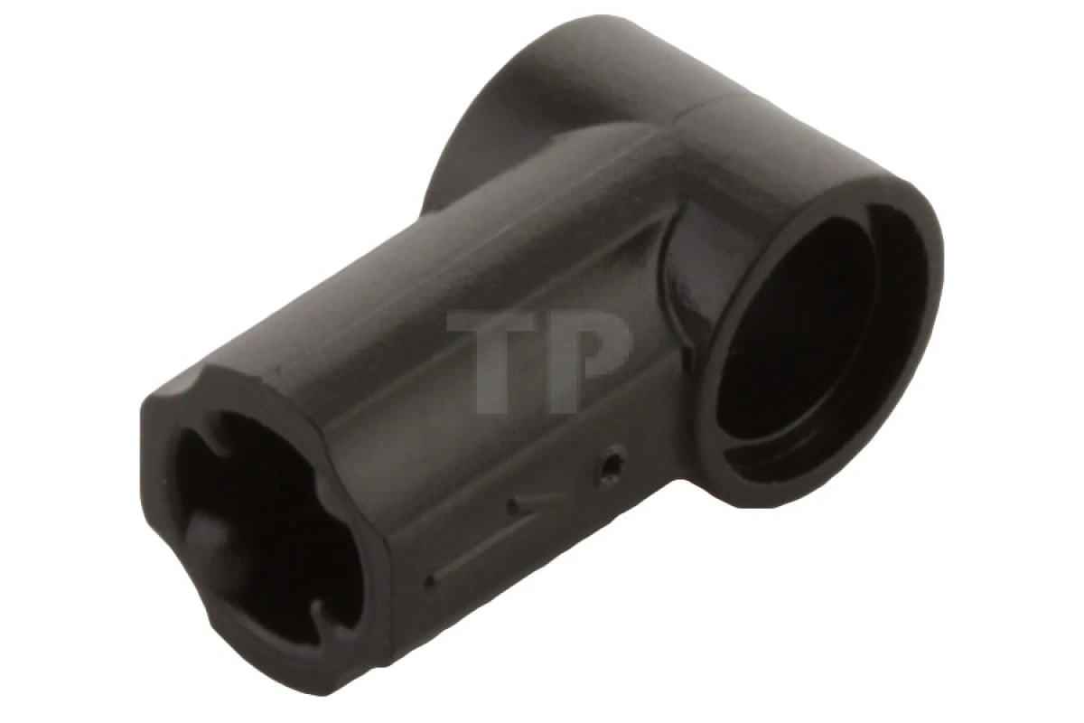 | Connect directional structure | 🛒 Shop |
| LM7805CT | 2 |
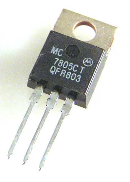 | Supply energy to huskylens directly of the batteries | 🛒 Shop |
| Electrolytic condenser 0,1 microfarad | 1 |
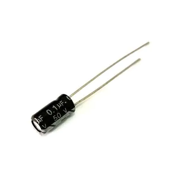 | (maker recommendation) | 🛒 Shop |
| Electrolytic condenser 0,33 microfarad | 1 |
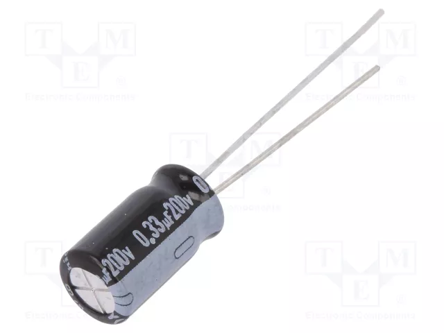 | (maker recommendation) | 🛒 Shop |
| Circuit board | 1 |
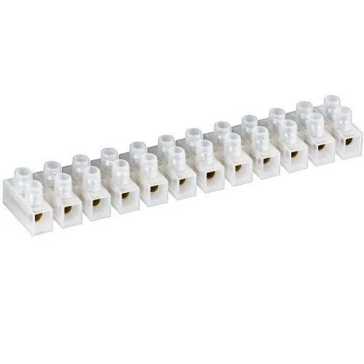 | Connect huskylens with the LM7805CT and then with batteries | 🛒 Shop |
| Differential QBX01 1:12 | 1 |
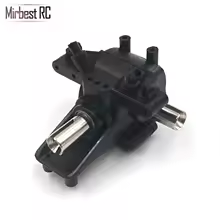 | It allows the drive wheels to rotate at different speeds on curves, preventing slippage | 🛒 Shop |
| Power Expansion Board Module | 2 |
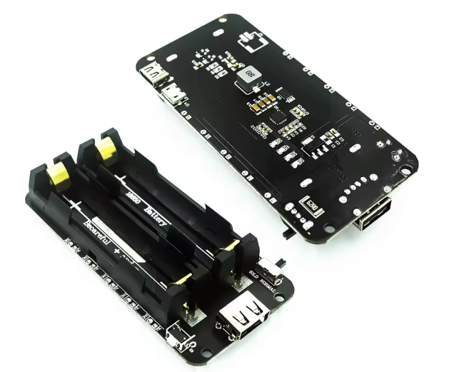 | It's a type of power bank where we've used the same Samsung batteries | 🛒 Shop |
| Micro Servo MG90S | 1 |
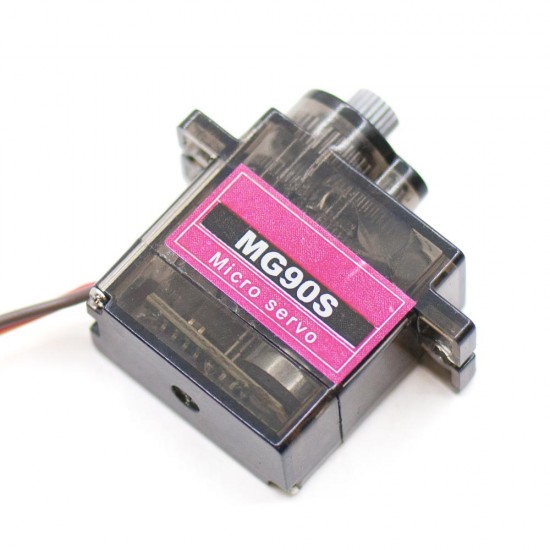 | Allow the camera to move and have a wider field of view | 🛒 Shop |"> Camera servo link |
| Heatsink | 1 |
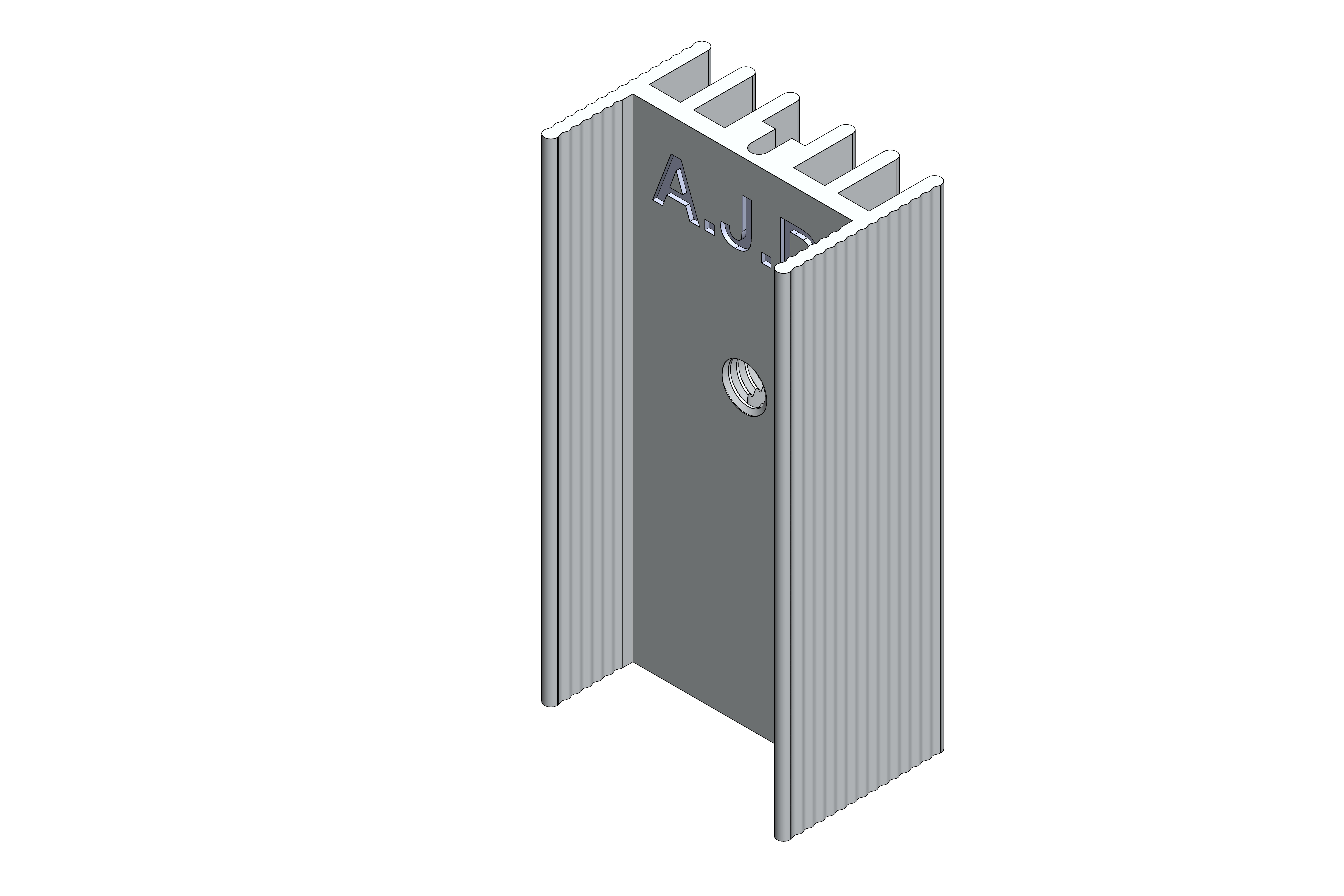 | Prevent the current regulator from overheating | 🛒 Shop |
| USB-Kabel | 1 |
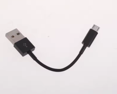 | It makes it easy to connect the robot to the computer to upload programmes or view the terminal when we’re carrying out tests, in a simple and convenient way that prevents the Raspberry Pi’s connector from breaking. | 🛒 Shop |
| Counterweight | 2 |
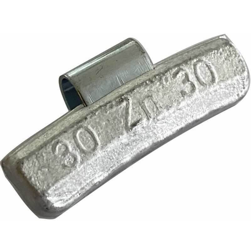 | We use it to adjust and balance the robot’s weight, as the rear is quite heavy due to the spoiler housing the batteries, which is why we place it at the front. In this case, there are two of them, and each one weighs 40 grams | 🛒 Shop |
4.3 Final version - Components and 3D designs
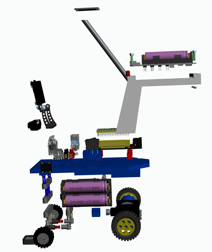
These are the 3D designs we have created, which include: a custom-made chassis for all components, a gear to connect the differential to the 360-degree servo, a rear wheel adapter to connect the differential shaft to the wheels and a mount for the HUSKYLENS module:
| Component | Quantity | Image | Function | File link |
| :---: | :---: | :---: | :---: | :---: |
| Chasis in 3D | 1 | 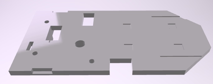 | Skeleton of the robot | [`📥Download`](models/CHASIS_modificado_2.stl) |
| Battery support 1 | 2 |
 | Support batteries | [`📥Download`](models/soportebateria1.stl) |
| Battery support 2 | 1 |
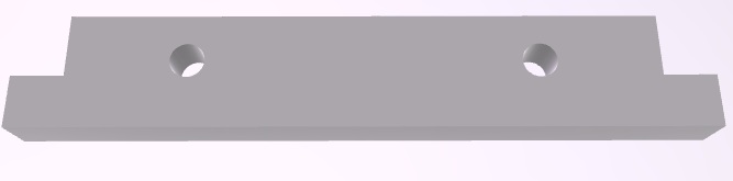 | Support batteries | [`📥Download`](models/soportebateria2.stl) |
| Switch support | 1 |
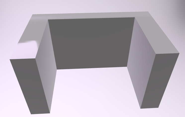 | Support the switch | [`📥Download`](models/SOPORTE_INTERRUPTOR.stl) |
| Adapter wheels in 3D | 2 |
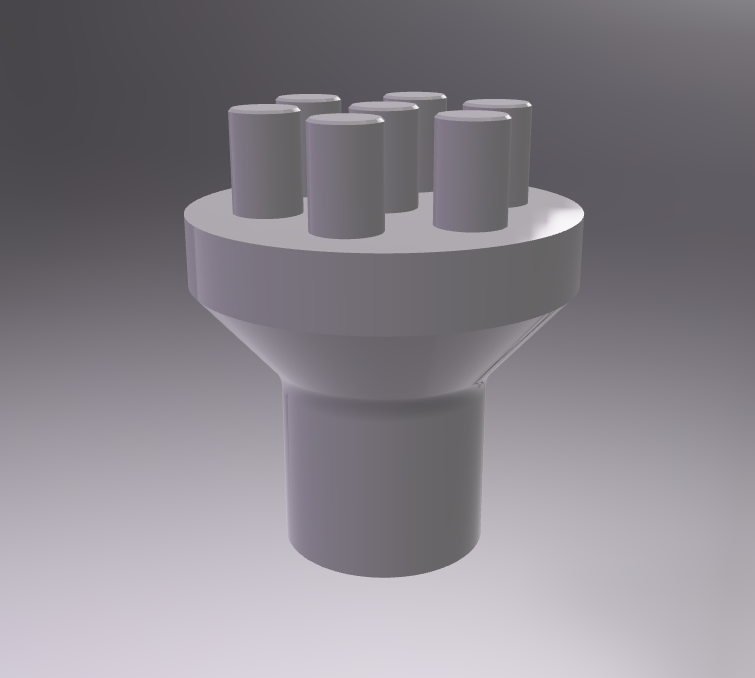 | Connect the wheels to the differential | [`📥Download`](models/wheel%20adapter.stl) |
| Adapter gear in 3D | 1 |
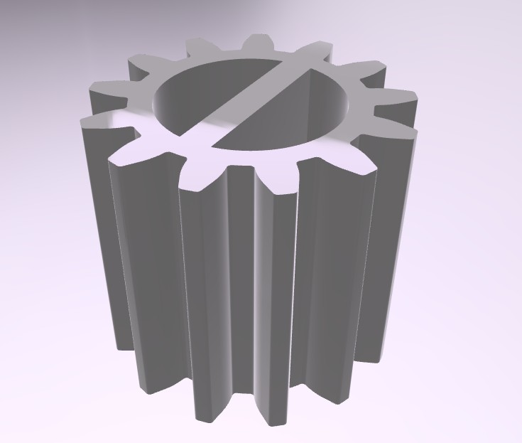 | Gearing with 360º servo gear | [`📥Download`](models/GEAR_ADAPTER.stl) |
| Magnetometer mast | 1 |
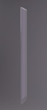 | Support the magnetometer | [`📥Download`](models/SOPORTE_10-DOF.stl) |
### 5. 🪛 Mobility design
This section includes an overview of the robot's components, speed and torque calculations, and the steering, motor and transmission systems.
5.1 First version - Mobility design
Generally speaking, the robot has:
* An Arduino R4 board (chosen based on previous experience programming it)
* Four HC-SR04 sensors (one at the front, one at the rear, and two on the sides, one on each side): the front and side sensors are mounted on top of the chassis on a small piece of foam board to...; the rear sensor is mounted underneath the chassis due to space constraints at the rear top of the chassis. The triggers for the four sensors are soldered to the same pin to save pins on the Arduino board, in case more components need to be connected.
* Four Samsung batteries... two of which power the Arduino board directly...
* A 360-degree servo that functions as a servo motor.
* A transmission system made with LEGO gears and one made with 3D-printed parts that runs from the servo motor to the mechanical differential.
* A mechanical differential equipped with two adapters for 3D printers to ensure a better fit on the wheels.
* Four LEGO wheels (two larger and two smaller: the specific models are listed in the parts list).
* Un sistema de dirección de LEGO (piezas usadas en la lista de componentes).
* An 180-degree servo to move the LEGO steering system via an arm attached to a string that runs to the steering system.
* A HUSKYLENS module for detecting obstacles.
* A foam board frame for holding a couple of batteries.
* A switch to turn on the robot.
* A button to start the program.
#### Steering system
The steering system used consists of:
* A system made from LEGO bricks from our Technology class, because it’s easy to assemble and disassemble and can be put together fairly quickly in case modifications are needed, featuring two LEGO wheels that are smaller than the rear ones.
* An 180-degree servo, since it’s easy to program and a larger turning angle wasn’t necessary given the system we built.
* A servo arm with a string, to connect the LEGO steering system to the servo.
If this steering turned too far in one direction, it would jam and could break. To prevent this, we adjusted the values using the steering servo calibration program so that this wouldn’t happen.
Micro servo 180
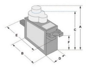
|
- A:32mm
- B:23mm
- C:28,5mm
- D:12mm
- E:32mm
- F:19mm
- Speed:0,1sec
- Torque:2,5kg-cm
- Weight:14,7g
- Voltage:4,8-6V
|
An important consideration regarding the robot’s balance was to place the heaviest components (the Arduino board, the batteries, the 360-degree servo) in the center of the chassis, maintaining a low and centralized center of mass. The batteries that directly power the 360-degree servo (explained in detail below) are located in a separate structure, as this was a last-minute modification.
The robot remained in that state for a time until we encountered several problems and some broken circuit boards, which forced us to build a mount for a second battery, as recommended in the instructions.
Finally, the servo we fitted to the HUSKYLENS to make the camera rotate was causing problems, so we decided to remove it and build a 3D structure to hold it in place, allowing us to view objects and lines from a better angle without needing a servo. We also positioned the camera so that it was pointing slightly downwards, to avoid confusion with other objects and colours in the surroundings.
5.2 Second version - Mobility design
Generally speaking, the robot has:
* Microcontroller: Raspberry Pi Pico 2 board on a KS3017 shield.
* Motor system: SPT5632-360 servo.
* Drivetrain: mechanical differential, gear system, differential-to-wheel adapters, and four LEGO wheels, two of which are larger than the others.
* Steering system: LEGO brick system, 180-degree micro servo, and a servo arm with a string to connect the micro servo to the steering system.
* Camera: HUSKYLENS module.
* Distance sensors: one TFmini-S sensor, two TOF400F sensors.
* Gyroscope: L3GD20 gyroscope.
* Color sensors: TCS34725 RGB sensor.
* Power supply: four Samsung ICR18650-26FU batteries, arranged in pairs across two battery expansion modules.
* Other components: a pushbutton to start the robot, a switch to turn on the batteries, a micro servo to rotate the HUSKYLENS and the TFmini-S sensor, red and green LEDs to provide hardware feedback on the program, and a heat sink connected to a current regulator for the HUSKYLENS module with two electrolytic capacitors.
All of the components mentioned above are explained in greater detail below.
#### Steering system
The steering system used consists of:
* A system made from LEGO bricks from our Technology class, because it’s easy to assemble and disassemble and can be put together fairly quickly in case modifications are needed, featuring two LEGO wheels that are smaller than the rear ones because they had to account for the height of the steering system.
* An 180-degree servo, since it’s easy to program and a larger turning angle wasn’t necessary given the system we built.
* A servo arm with a string, to connect the LEGO steering system to the servo.
If this steering turned too far in one direction, it would jam and could break. To prevent this, we adjusted the values using the steering servo calibration program so that this wouldn’t happen.
Micro servo 180
|
- A:32mm
- B:23mm
- C:28,5mm
- D:12mm
- E:32mm
- F:19mm
- Speed:0,1sec
- Torque:2,5kg-cm
- Weight:14,7g
- Voltage:4,8-6V
|
|
|
- Type: 360° continuous rotation digital servo
- Voltage: 4.8–8.4 V
- Speed: 56–88 rpm
- Rated current: 1.5 A
- Maximum current: 2.5 A
- Gears: Metal
- Motor: Coreless
- Weight: ≈58 g
- Dimensions: 40.5 × 20 × 37.5 mm
|
Torque of each wheel:
F= 2 N
r= 21,5 mm = 0,0212 m
T= 2 N · 0,0212 m = 0,0424 N·m
#### Chassis design
The chassis has evolved based on the need to add or remove components, and depending on what was most practical for meeting the challenges.
Initially, we used a sheet of foam board that was in the classroom, onto which we gradually added all the components. To attach the components, we used hot glue (because it has good adhesive properties, allows us to make modifications easily, and doesn’t damage the components). In fact, the first prototype was tested with a foam board base.
The front is cut into a pointed shape to prevent it from coming into contact with any of the interior partition walls or those of the parking garage during the obstacle phase.
After confirming that this was the final base, we designed the chassis in 3D, printed it, and transferred the components from one base to the other. Although we thought this change might cause problems once everything was already assembled, there were none.
The robot remained in this configuration for a while until we encountered several issues and broken circuit boards, which forced us to build a mount for a second battery as recommended in the instructions. Initially, it was made of foam board since it was a last-minute modification, but it was later 3D-designed to ensure a more durable and reliable material over time.
Finally, after the regional competition, the chassis had bent under the weight of the components, so we designed a new one with minor modifications—thicker so it could easily support them over time.
An important consideration regarding the robot’s balance was to place the heaviest components—the Raspberry Pi Pico 2 board with its shield, the SPT5632-360 servo, and a pair of batteries with their expansion module—in the center of the chassis, ensuring a low and centralized center of mass.
However, the addition of the other two batteries—a last-minute modification—forced us to build a special structure for them at the rear of the robot. Over time, it became apparent that when accelerating, the robot would sometimes skid due to an overload at the rear. To compensate for this extra weight, lead plates were added to the front of the robot.
The chassis was always designed to provide a stable and reliable foundation on which to mount the components, avoid unnecessary wiring, provide specific spaces for certain components, save space, and keep the robot compact throughout its journey through the challenges.
5.3 Final version - Mobility design
### 6. ⚡ Power and Sensor Architecture
This section includes the robot's power supply, the wiring diagram created in Cirkit Designer, everything related to the sensors that provide information to the board, and the reasoning behind the sensor layout.
6.1 Old Power and Sensor Architecture
#### Power Supply
The robot uses four Samsung ICR18650-26FU batteries as its power source. Two batteries power the Arduino R4 board, and the other two directly power the 360-degree servo motor. This prevents interference with the servo, allowing the robot to move smoothly.
An energy estimate was calculated for all components to determine the appropriate batteries:
* HUSKYLENS module: 230–420 mA.
* Arduino R4 Minima board: 100 mA.
* HC-SR04 sensors: 15 mA
* 180-degree microservo: 200 mA
* 360-degree continuous rotation servo: 700 mA
* Total: 1215 mA
Theoretically, this is the robot’s power consumption. However, after measuring the robot’s actual power consumption, it was 500 mA. Therefore, with two batteries (2600 mA), we have enough power for 5 hours. These were the initial calculations since we were only going to use two batteries. Finally, after verifying that using two batteries connected directly to the 360-degree servo and the HUSKYLENS module works as intended, we will now connect four batteries (5200 mA), which theoretically gives us:
* Battery life for the 360° servo and the HUSKYLENS camera (8.4 V and 2600 mA): approximately 2.5 hours.
* Battery life for the Arduino board (4.2 V and 5200 mA): approximately 16 hours.
This means we need to be careful with the batteries for the 360° servo and the HUSKYLENS module because they may fail due to a lack of power.
Based on this estimate and the availability of batteries in our class, we chose the Samsung ICR18650-26FU model. The main features of this model are:
The batteries that power the board are placed in a dedicated space on the 3D-printed chassis. Initially, in the prototype with the foam board base, they were glued to the bottom of the base, as seen in the initial sketches of the component layout. Later, it was decided to create a custom-made 3D-printed space for them in that same location.
The batteries that power the servo, being a last-minute modification, have been placed in a foam board structure on the upper rear of the robot. This also extends the parking length and allows us to exit the parking space in the obstacle course with more room to maneuver.
To power the HUSKYLENS module, an LM7805 regulator has been included to step down the voltage from the batteries from 8.4 V to 5 V. Electrolytic capacitors have also been included as recommended by the manufacturer.
#### Wiring Scheme
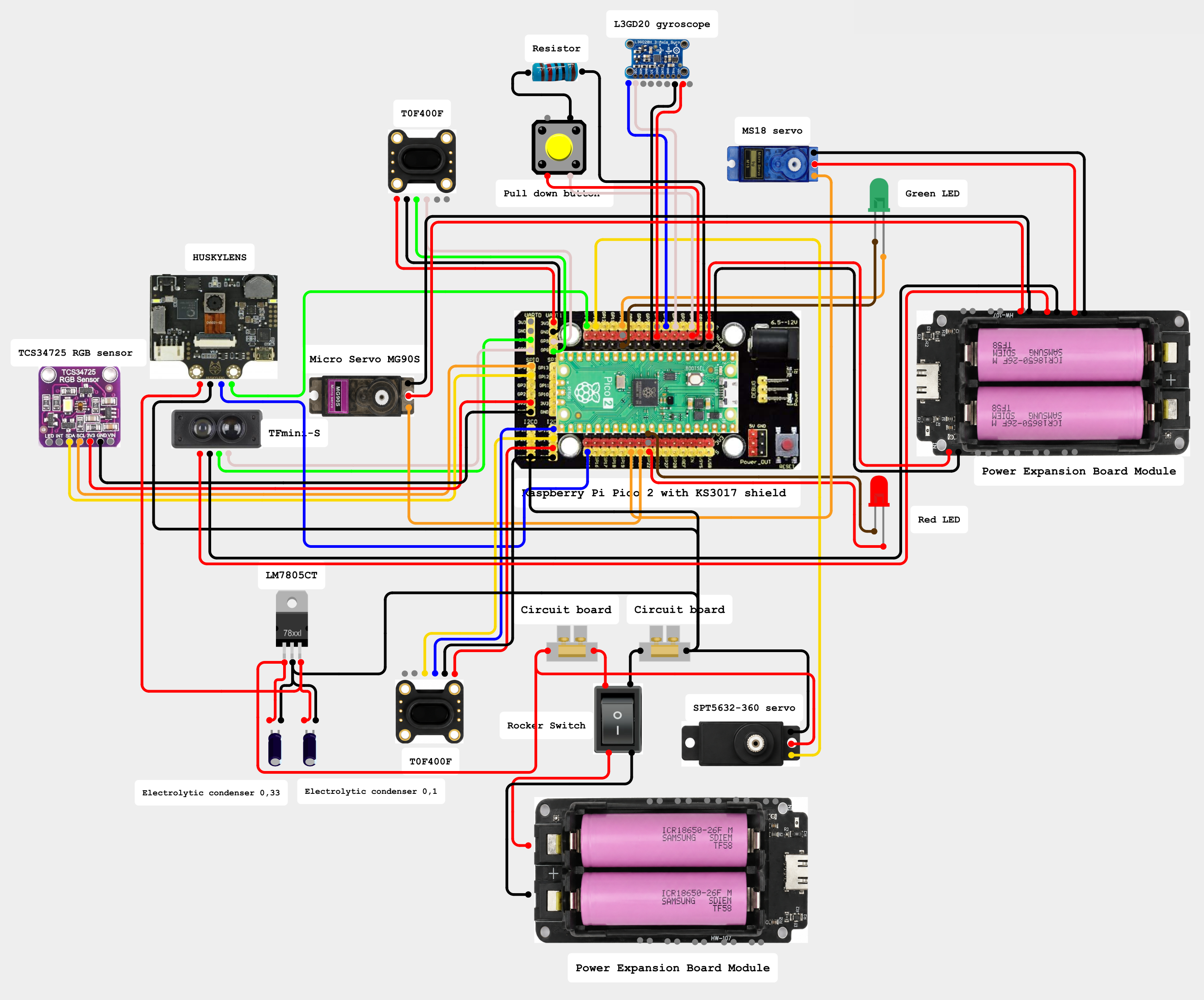
The wiring diagram used for assembling the robot is shown in the image below. It was created in TinkerCad based on previous experience using this program. Some components were not available in TinkerCad, so similar ones that met the necessary connection requirements were used, and their names were noted on the final diagram to avoid confusion:
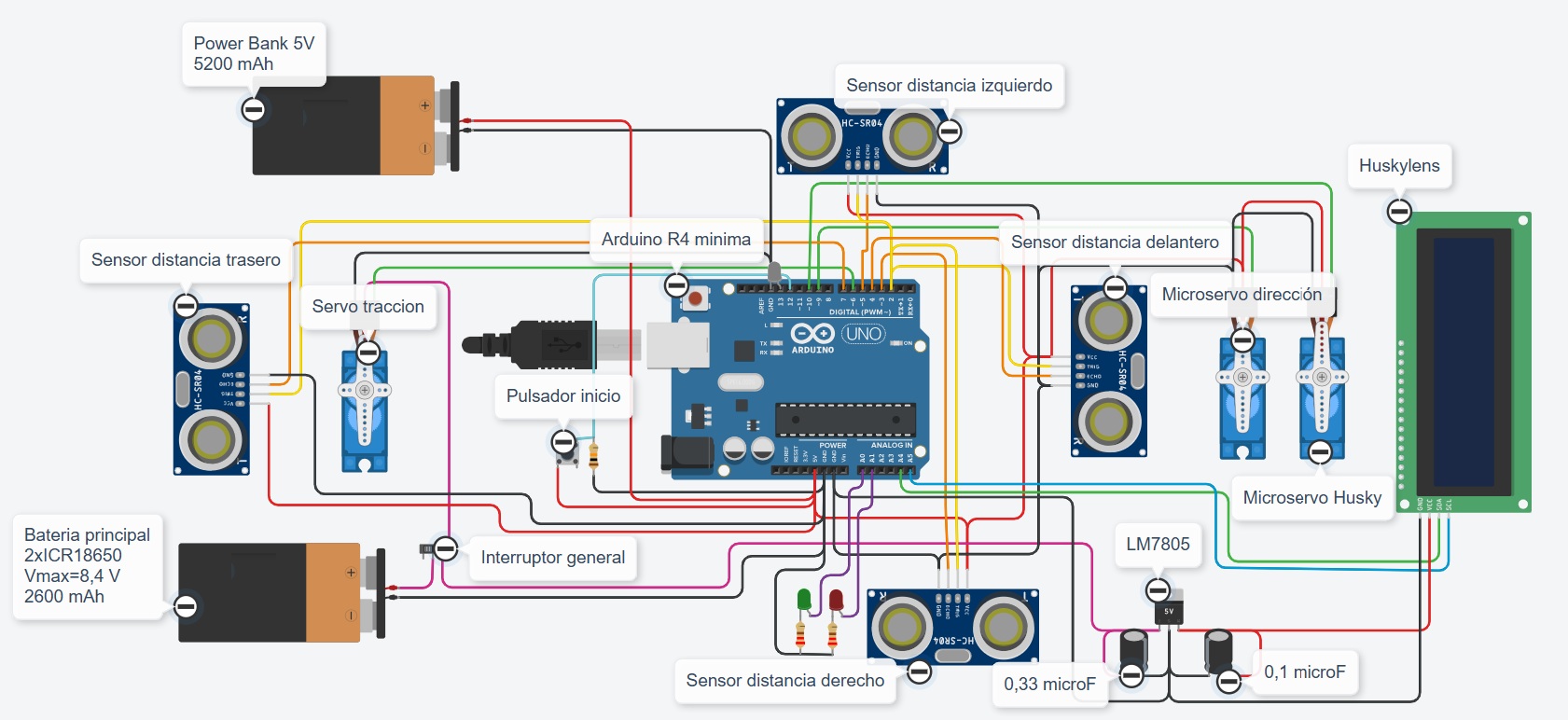 #### Sensors
The robot receives data from three main components: the Arduino R4 Minima board, the HC-SR04 sensors, and the HUSKYLENS module.
The Arduino R4 Minima board was chosen because it has additional pins that other Arduino boards do not have, ensuring there are enough pins to connect all the components. However, after an accident in which this board stopped working, we considered replacing it with an Arduino R4 Wi-Fi board we had in class, without using the Wi-Fi and Bluetooth functions, since that would violate the rules. In the end, we used another Arduino UNO R4 Minima board and attached a shield to it so we could access all the pins we had before.
The HC-SR04 sensors were chosen after considering three types of sensors: the HC-SR04, the CJVL53L0XV2 (which use lasers), and the TOF10120 (which also use lasers). Initially, the CJVL53L0XV2 was chosen, although it was later replaced due to programming issues. The HC-SR04, although less efficient, is easier to program, and we had used it before.
We started by installing three sensors (two on the sides and one at the front), because we thought that would be enough to park and navigate turns without any problems. However, adding a fourth sensor—mounted on the lower rear of the robot—provided more accurate measurements that helped us overcome challenges (specifically the parking portion of the obstacle course) more easily.
|
|
- Operating Voltage: 5V DC
- Quiescent Current: < 2mA
- Operating Current: 15mA
- Measuring Range: 2–450 cm
- Accuracy: ±3 mm
- Beam Angle: 15°
- Ultrasonic Frequency: 40 kHz
- Minimum TRIG trigger pulse duration (TTL level): 10 μs
- Output ECO pulse duration (TTL level): 100–25,000 μs
- Dimensions: 45 × 20 × 15 mm
- Minimum wait time between one measurement and the start of the next: 20 ms (50 ms recommended)
|
6.2 Current Power and Sensor Architecture
#### Power Supply
The robot runs on four Samsung ICR18650-26FU batteries. Two of the batteries directly power the two mini-servos (the one on the HUSKYLENS module and the steering servo), the TF-Mini S sensor, and the Raspberry Pi Pico 2 board, while the other two power the drive servo and the HUSKYLENS.
An energy calculation was performed, taking all components into account, to help select the batteries:
| Battery one🔋(the one on the wing) |
Battery two⚡(the one underneath the chassis) |
| Electronic device |
milliampere-hours consumed (mA/h) |
Volts (V) |
Electronic device |
milliampere consumed (mA) |
volts (V) |
| Raspberry Pi Pico 2 board |
40 mA |
3,3 V |
360° continuous rotation servo |
700 mA |
8,4 V |
| TOF400F (right and left) |
40 mA |
3,3 V |
HUSKYLENS module |
230–420 mA |
5 V |
| LEDS |
15 mA |
3,3 V |
|
|
|
| TFmini-S |
140 mA |
5 V |
|
|
|
| 180 microservo direction |
200 mA |
5 V |
|
|
|
| 10DOF magnetometer |
6 mA |
3,3 V |
|
|
|
| Huskylens and TFmini micro-servo |
200 mA |
5 V |
|
|
|
| RGB sensor TCS34725 |
6 mA |
3,3 V |
|
|
|
* Total: approximately 1,600 mA
Based on this data, the approximate theoretical battery life would be:
* Battery life for the traction servo and the HUSKYLENS camera (8.4 V and 2,600 mAh): approximately 2,5 hours.
* Battery life for the Raspberry Pi Pico 2 board, TFmini-S sensor, and mini servos (4.2 V and 5,200 mAh): approximately 12 hours.
This means we need to be careful with the batteries for the 360° servo and the HUSKYLENS module, as they may fail due to a lack of power.
It’s clear that we have more than enough battery power to cover the robot’s components’ power consumption, but even so, we’ve opted to have a bit of a reserve so we don’t have to worry about recharging the batteries every so often. Normally, the batteries can last up to two or three weeks, depending on whether I use it or whether we carry out a lot of tests with the robot.
Given this budget and the availability of batteries in our category, we chose the Samsung ICR18650-26FU model. The main features of this model are:
|
|
- Brand: Samsung
- Model: ICR 18650-26FU
- Capacity: Nominal capacity: 2600 mAh
- Voltage: 3.7 V nominal
- Charging: 4.2 V maximum, 1300 mA standard, 2600 mA maximum
- Discharge: Cut-off at 2.75 V, standard 520 mA, maximum 5200 mA
- Description: Pink cell casing, white insulating ring, 18650 format
|
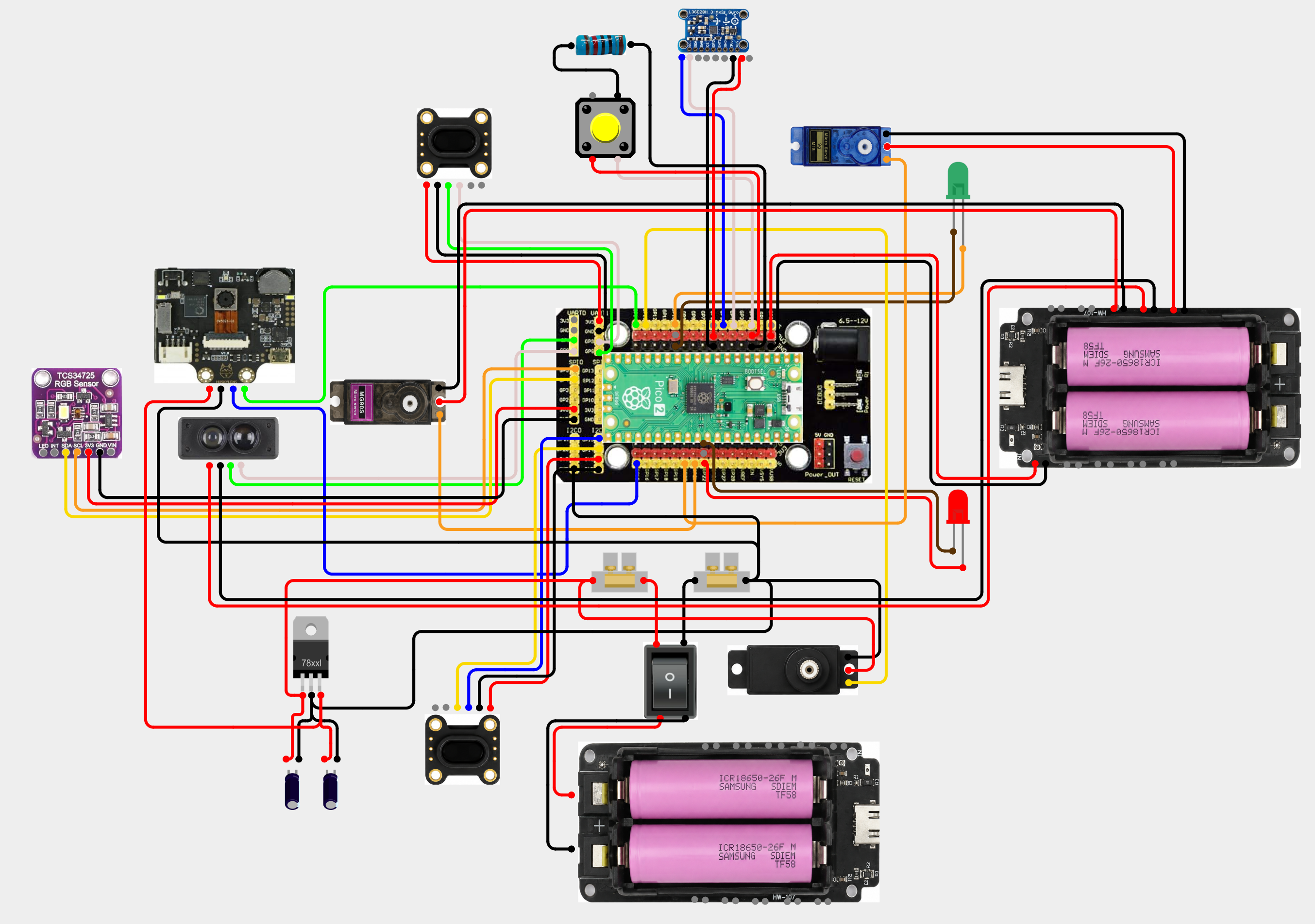 #### Sensors
The robot receives data from six main components: the Raspberry Pi Pico 2 board, the TFmini-S distance sensor, the TOF400F distance sensors, the HUSKYLENS module, the TCS34725 RGB sensor, and the L3GD20 gyroscope.
The Raspberry Pi Pico 2 board was chosen after the regional competition. Initially, we used an Arduino R4 Minima board, but it was clear that a more powerful microcontroller was needed to handle such a large amount of data. There were other options, but they presented serious programming challenges. By using this board, the entire program was written in Python, which presented difficulties compared to the code from the regional competition, which was in C++.
This board is mounted on a KS3017 display to allow for convenient connection of the cables from the other components; otherwise, the cables for all components would have to be soldered.
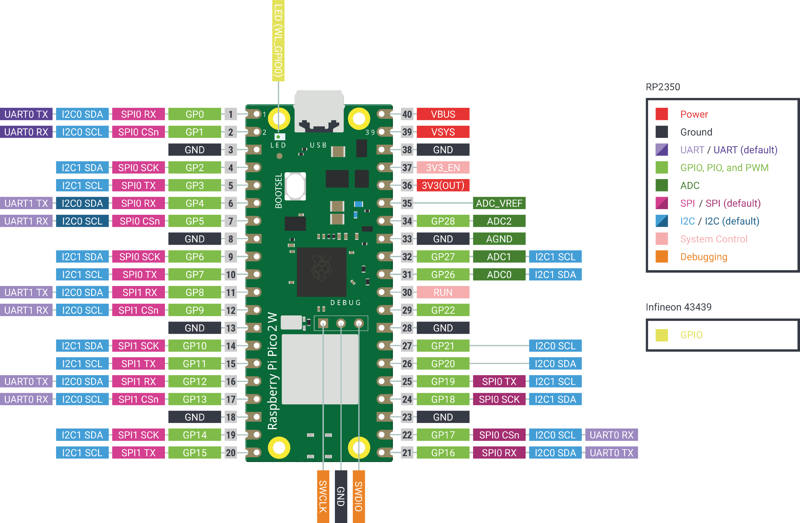
|
- Dimensions: 21 mm x 51 mm
- CPU: Dual-core Cortex-M33 or RISC-V Hazard3 processors at 150 MHz
- Memory: 520 KB of on-chip SRAM
- Flash: 4 MB of on-chip QSPI flash memory
- Interface: 26 multipurpose GPIO pins (5V-tolerant), including 4 that can be used for ADC
- Peripherals: 2 × UART, 2 × SPI controllers, 2 × I2C controllers, 16 × PWM channels, 1 × USB 1.1 and PHY controller, with support for host and device modes, 12 × PIO state machines
- Power supply: 1.8–5.5 V DC
|
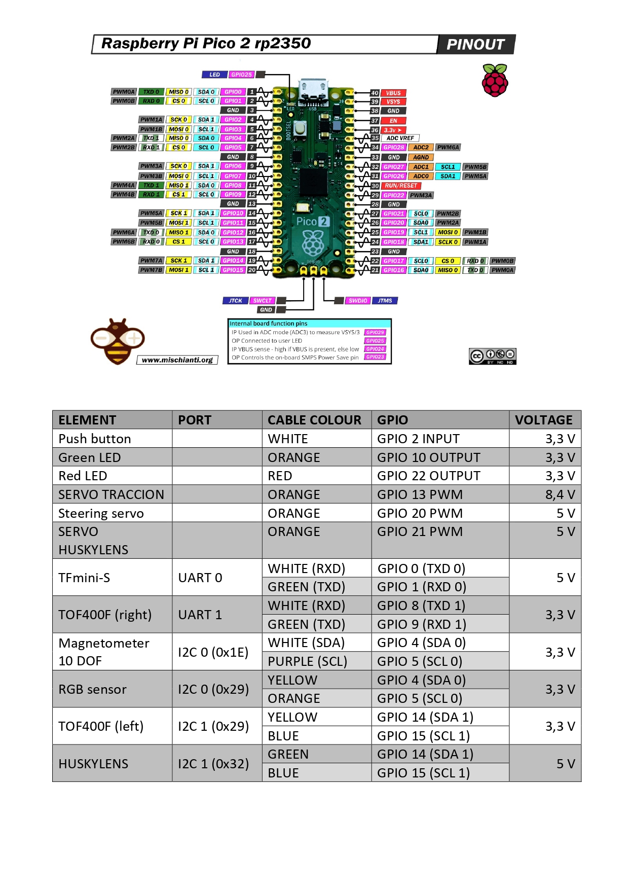 The TFmini-S sensor was chosen from among other options from the same manufacturer (as explained in greater detail in the project log); ultimately, this sensor has a detection range that is more than sufficient for the challenge, low power consumption, excellent accuracy, and a reasonable price. The other options were either too expensive or not up to par. Furthermore, during the regional phase, we had used HC-SR04 ultrasonic sensors, which worked at the time, but for this national phase we needed more accurate and reliable sensors, so we looked for laser sensors.
|
|
- Measurement principle: Time of flight (ToF) using a single-channel LiDAR sensor.
- Detection range: 0.1 meters to 12 meters
- Blind spot: 10 cm
- Sampling frequency: Adjustable between 1 Hz and 1,000 Hz (100 Hz by default)
- Accuracy: ±6 cm (from 0.1 to 6 m) / ±1% (from 6 to 12 m).
- Field of view (FoV): 2 degrees.
- Light source: 850 nm infrared VCSEL emitter (Eye Safety Class 1).
- Supply voltage: 5 V DC (±0.1 V)
- Current consumption: Average ≤140 mA (peaks of 200 mA)
- Dimensions and weight: 42 mm × 15 mm × 16 mm / 5 grams
- Ambient light immunity: Up to 70 Klux
|
|
|
- Internal Core Chip: Based on the STMicroelectronics VL53L1X Time-of-Flight laser sensor.
- Useful Measurement Range: 4 cm – 400 cm (4 meters)
- Dead Zone (Maximum Proximity): 0 to 4 cm
- Supply Voltage: Supports 3.3V and 5V DC
- Current Consumption: ~20 mA in standby / ~40 mA maximum during laser emission
- Emitter Technology: 940 nm invisible infrared VCSEL laser
- Receiver Array: SPAD array
- Field of View (FoV): 27°
- Refresh Rate: Up to 50 Hz
- Ambient Light Immunity: Very high
|
|
|
- Core Processor Chip: Dual-core RISC-V processor
- Integrated Image Sensor: Omnivision OV2640 2.0-megapixel camera
- Built-in Display: 2.0-inch IPS LCD display with a resolution of 320x240 pixels.
- Supply Voltage: 3.3V to 5.0V DC.
- Current Consumption: ~320 mA at 3.3V / ~230 mA at 5.0V
- Frame Rate: Up to 30 frames per second
- Illumination: Features 2 built-in front LEDs
- Physical Dimensions: 52 mm × 44.5 mm (2.05“ × 1.75”).
|
|
|
- Detection Channels (RGBC): 4 independent channels: Red, Green, Blue, and Clear
- Resolution per Channel: 16-bit precision per channel
- Integrated Physical Filter: Features an infrared (IR) blocking filter positioned directly over the photodiodes
- Dynamic Range: Extreme, with a ratio of 3,800,000:1
- Recommended Measurement Distance: between 3 mm and 10 mm
- Supply Voltage: Supports 3.3V and 5V DC
- Current Consumption: ~2.5 uA in deep sleep mode / up to 20 mA when operating with LEDs on
- Illumination: 1 or more high-brightness white LEDs
|
|
|
- Type: 3-axis MEMS gyroscope
- Axes: X, Y, and Z
- Measurement range: ±250, ±500, and ±2000 °/s
- Interface: I²C / SPI
- Supply voltage: 2.4–3.6 V
- Current consumption: approx. 6.1 mA during operation
- Resolution: 16 bits
- Output frequency: up to 760 Hz
- Sensing: angular velocity on all three axes
- Operating temperature: −40 to +85 °C
- Applications: orientation, motion, and rotation sensing, as well as stabilization.
|
### 7. 🧠 Strategy
Here you can find the strategy we have followed to complete both challenges
7.1 Old strategy
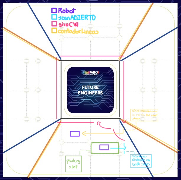 clock-wise mode |
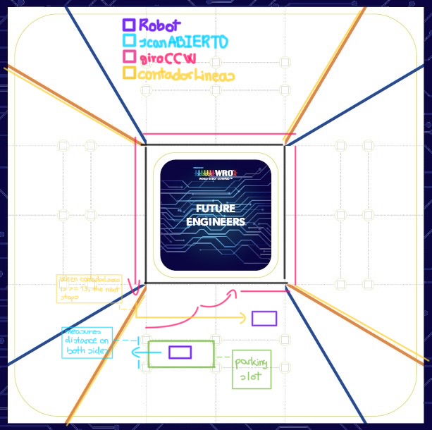 counter clock-wise mode |
For this setup, we’ve decided to rely primarily on ultrasonic sensors, though we also use the HUSKYLENS machine vision camera.
We start by exiting the parking area, then reverse to check which direction we’re facing (clockwise or counterclockwise). Then:
* If the distance on the right is shorter than the distance on the left, we’re facing counterclockwise. Once we know this, we move forward to the center of the field and begin circling. We chose to go through the center of the field for two reasons: first, since we have to cover less distance, it would take us less time to complete the laps; second, we believe that, by using distance sensors, this option would be easier to program and cause fewer measurement issues.
* If the distance to the right is greater than the distance to the left, we would be moving clockwise. Once we know this, we move to the center of the field and begin circling. We chose to go through the center of the field for the reasons explained in the previous paragraph.
While this is running, we use HUSKYLENS to count the red lines on the field floor; this way, we can determine the number of laps the robot has completed and make it stop after completing the required three laps.
We have not yet developed a specific strategy for parking in the parking zone due to lack of time; however, we continue to working on that.
#### Obstacle challenge
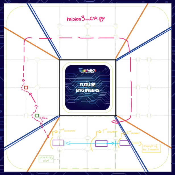 clock-wise mode |
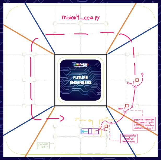 counter clock-wise mode |
7.2 Current strategy
After much testing, trial and error, and various strategies, we finally settled on the definitive one (you can see the process leading up to this documented in ‘Daily documentation’). Before discussing the specific strategy for each challenge, let’s explain how we distinguish one challenge from another. To do this, we used the most obvious difference between the two: the presence of obstacles in the Obstacle Challenge and their absence in the Open Challenge. As it is difficult to describe the strategy in writing, we have attached an image showing the diagram.
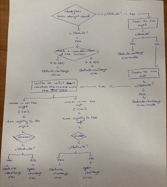
#### Open challenge
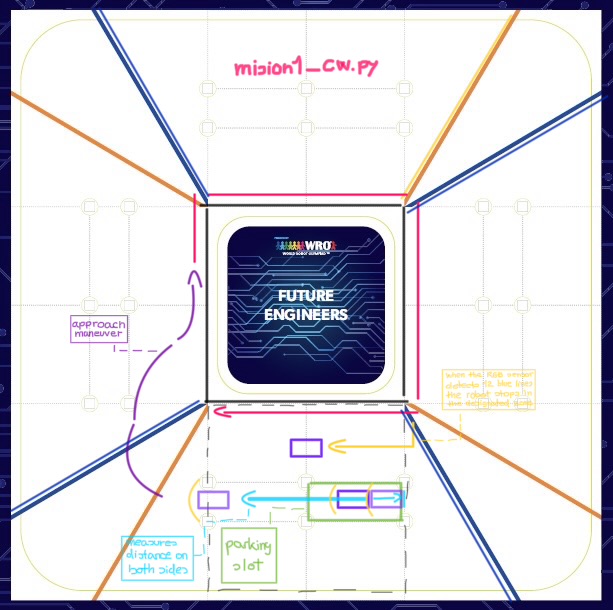 clock-wise mode |
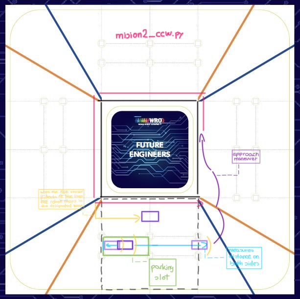 counter clock-wise mode |
|
clock-wise mode
|
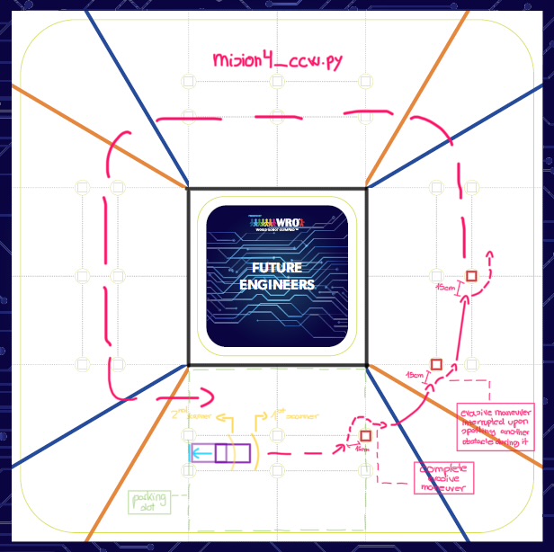 counter clock-wise mode |
For this challenge, we used laser distance sensors (TF-mini-S and TOF400F), the TCS34725 RGB sensor, the HUSKYLENS machine vision camera and the 10-DOF IMU sensor. Of the two options available to us (exiting the parking area from the previous challenge or exiting a car park), we chose to exit the same area as in the previous challenge because the HUSKYLENS cannot distinguish between magenta and red; in other words, it sees magenta as if it were red (something that sometimes also happens with orange). It is true that we spent most of the time working with the car park, but given that this often caused us problems and we could not think of a way to identify or distinguish the car park other than by colour (an unviable strategy), we decided to change it at the last minute. Having covered these specifications, we move on to the strategy. There are three ways to approach this challenge (as per the diagram above):
* It spots a block on the first front scanner: in this case, it checks the direction; if the block is on the right-hand side of the screen, it’s CW, whilst if it’s on the left-hand side, it’s CCW. We make use of this distinction by exploiting the fact that blocks cannot be placed on the line next to the outer wall. As soon as it knows the direction, it heads towards it and starts looking for obstacles.
* It does not see an obstacle in the first front-facing scanner, but it does when it looks to the left and to the right: in this case, as it already knows the direction is towards it, it immediately starts scanning for obstacles.
* It does not detect a block with the first front scanner, nor when it looks to the left or right, but it does when it turns at the corner: in this other case, as it also knows the direction is towards it, it immediately starts searching for obstacles.
From this point onwards, the strategy is always the same: to search for obstacles. Even so, let’s highlight a few cases:
* When the robot detects a blue line with the RGB sensor, it knows it is changing section and, if it does not see any objects, it turns 90° in the corresponding direction depending on the street number (1, 2, 3, 4). We do this to prevent the robot from becoming disoriented by searching on the wrong side or crashing into the wall whilst scanning.
* Whilst performing the obstacle-avoidance manoeuvre (which consists of two phases), upon completing phase 1, it scans to check if it can see another block; if it sees none, it completes the manoeuvre, and if it sees one, it heads straight for it without completing the manoeuvre. We did this because we realised that a lot of time was being wasted finishing the avoidance manoeuvre when the robot could be heading towards another pillar, as well as complicating the manoeuvre to avoid the next pillar (if one exists) in 40% of cases.
* When the robot gets too close to an obstacle before avoiding it, it goes backwards. This is something we do to reach the perfect distance to avoid it before starting the obstacle-avoidance maneuver and, this way, we prevent moving the obstacle from its original place and, by consequence, get disqualified.
While we do all that, the RGB sensor is counting the blue lines on the floor to know when to stop (when this counter becomes 12 // 3 laps).
### 8. 💻 Software
Here you can find almost all programs used in the development of our robot; including flowcharts, test programs and each version of the final program we have made.
#### 8.1 Old programs (Arduino - C++)
📋 Test programs
These are all programs we used to calibrate sensor and conduct functional tests:
* [00_I2C_SCAN.ino](src/Old_programs/Test_programs1/00_I2C_SCAN.ino) ➜ to check the 12C addresses
* [01-MAGNETOMETRO.ino](src/Old_programs/Test_programs1/01-MAGNETOMETRO.ino) ➜ to check the compass bearing of the magnetometer (which we did not use at the end)
* [03_EJEMPLO_TOFx2.ino](src/Old_programs/Test_programs1/03_EJEMPLO_TOFx2.ino) ➜ to test the operation of two TOF400F at the same time
* [11_JOYSTICK_CON_2_SERVOS.ino](src/Old_programs/Test_programs1/11_JOYSTICK_CON_2_SERVOS.ino) ➜ to calibrate the steering servo
* [11_POTENCIOMETRO_CON_1_SERVO.ino](src/Old_programs/Test_programs1/11_POTENCIOMETRO_CON_1_SERVO.ino) ➜ to calibrate the drive servo
* [CALIBRAR_MAGNETOMETRO.ino](src/Old_programs/Test_programs1/CALIBRAR_MAGNETOMETRO.ino) ➜ to test the magnetometer's gyroscope
* [HCSR04_x1.ino](src/Old_programs/Test_programs1/HCSR04_x1.ino) ➜ to test the operation of the HCSR04
* [HCSR04_x4.ino](src/Old_programs/Test_programs1/HCSR04_x4.ino) ➜ to test the operation of four HCSR04 at the same time
* [HCSR04_x4_display.ino](src/Old_programs/Test_programs1/HCSR04_x4_display.ino) ➜ to test the operation of four HCSR04 at the same time while the text is being printed on a display
* [HUSKYLENS_I2C.ino](src/Old_programs/Test_programs1/HUSKYLENS_I2C.ino) ➜ an example of a HUSKYLENS connected by I2C library
* [HUSKYLENS_OBJECT_TRACKING.ino](src/Old_programs/Test_programs1/HUSKYLENS_OBJECT_TRACKING.ino) ➜ to test the OBJECT TRACKING mode of the HUSKYLENS
💻 Final program
This is our old final program, which allowed us to reach the national WRO final:
```cpp
#include //Cable verde al A4 y cable azul al A5
#include
HUSKYLENS huskylens;
const int rojo = 1;
const int verde = 2;
#include
HCSR04 hc(2, new int[4]{3, 4, 5, 7}, 4); //initialisation class HCSR04 (trig pin , echo pin, number of sensor)
#include
Servo servoTraccion;
Servo servoDireccion;
Servo SERVOcam;
#define ledV 14
#define ledR 15
int i=0;
int dir=90;
int distDE=15; // SENSOR 0 derecho
int distFR=110; // SENSOR 1 frontal
int distIZ=15; // SENSOR 2 izquierdo
int distTR=15; // SENSOR 3 trasero
// Variables control servos
int Izda=134;
int Dcha=54;
int Recto=94;
int Para=90;
int Avanza=0;
int Retrocede=180;
int lectura=0;
int CASO;
//variable para esquivar obstáculos.
int anguloCam = 86; // guarda la posicion actual del servo de la camara
int direccionBarrido = 5; // velocidad y sentido del barrido (positivo derecha, negativo izquierda)
unsigned long tiempoCam = 0; // controla el refresco del movimiento del servo de la camara
int ladoBusqueda = 1; // 1 = empezar a la derecha, 2 = empezar a la izquierda
//variables para contar vueltas en el desafío libre.
int contadorLineas = 0; // guarda las lineas rojas que va cruzando
unsigned long tiempoBloqueoRojo = 0; // guarda el momento exacto en que pisa el rojo
bool rojoBloqueado = false; // bandera para saber si esta en el tiempo de espera
void setup()
{ //Serial.begin(9600);
Wire.begin(); // Iniciar el bus I2C
pinMode (12, INPUT);
pinMode (13, OUTPUT);
pinMode(ledV, OUTPUT); //led verde
pinMode(ledR, OUTPUT); //led rojo
servoTraccion.attach(6); // 0 AVANZA 90 STOP 180 RETROCEDE
servoDireccion.attach(9); // 50 DCHA 90 RECTO 130 IZDA
SERVOcam.attach(10); // 0 DCHA 86 RECTO 172 IZDA
servoTraccion.write(Para);
servoDireccion.write(Recto);
SERVOcam.write(86);
while (!huskylens.begin(Wire)) { // Con el while, el programa no continua hasta que se inicie la cámara
//Serial.println("Error al iniciar HuskyLens");
digitalWrite(13, HIGH);
delay(1000);}
//Huskylens iniciado
digitalWrite(13, LOW);
delay(300);
huskylens.writeAlgorithm(ALGORITHM_OBJECT_TRACKING);
delay(300);
while (digitalRead(12) == LOW) { //espera al pulsador de inicio mientras parpadea el led
digitalWrite(13, HIGH);
delay(100);
digitalWrite(13, LOW);
delay(100);
}
}
void scan1(){ //para ver en qué zona está
while (true){ //lectura segura
distFR=hc.dist(1);
delay(60);
if ((distFR>2)&&(distFR<250))
{break;}
}
if (distFR > 40) {
digitalWrite(ledV, HIGH);
delay(2000);
digitalWrite(ledV, LOW);
CASO=1; //El robot esta en la zona de salida
scanABIERTO();
}
if (distFR < 40) {
digitalWrite(ledR, HIGH);
delay(2000);
digitalWrite(ledR, LOW);
CASO=2; //El robot esta en el aparcamiento
scanOBSTACULOS();
}
}
////////////////////zona Desafio Abierto////////////////////////////////
void scanABIERTO(){ //aquí comprueba el sentido de giro
while (true){
servoDireccion.write(Recto);
servoTraccion.write(105); //atras despacito hasta ver el hueco con un sensor lateral
distDE=hc.dist(0);
delay(30);
distIZ=hc.dist(2);
delay(30);
if ((distDE>90)||(distIZ>90)) //detecta hueco a un lado
{ delay(30);
servoTraccion.write(Para);
break;}
}
if (distDE < distIZ) {
giroCCW();
} //CCW a izquierdas
if (distDE > distIZ) {
giroCW();
} //CW a derechas
}
void giroCW(){
servoDireccion.write(70); //maniobra de aproximacíon
servoTraccion.write(70);
delay(2100);
servoDireccion.write(110);
servoTraccion.write(70);
huskylens.writeAlgorithm(ALGORITHM_COLOR_RECOGNITION); //cuenta las vueltas por las lineas naranja de las esquinas
delay(2400);
while(true) { //empieza a seguir la pared interior a 15 cm
servoTraccion.write(0);
servoDireccion.write(dir);
distDE=hc.dist(0);
delay(30);
dir=(80-3*(-15+distDE)); //15 es la distancia a la pared y *3 es el factor de coreección de la dirección
dir = constrain(dir, Dcha, Izda); // Dcha<90 y Izda>90
servoDireccion.write(dir);
// aquí cuenta las líneas de color naranja
// si está en tiempo de espera, mira si ya pasaron los 3 segundos para desbloquear
if (rojoBloqueado) {
if (millis() - tiempoBloqueoRojo > 3000) {
rojoBloqueado = false; // al pasar la linea, vuelve a activar el sensor
}
}
// si el sensor esta activo pide datos a la huskylens
if (!rojoBloqueado && huskylens.request() && huskylens.available()) {
HUSKYLENSResult colorSuelo = huskylens.read();
if (colorSuelo.command == COMMAND_RETURN_BLOCK) {
// si ve la linea naranja y ademas esta en la parte baja de la pantalla (cerca del coche)
if (colorSuelo.ID == rojo && colorSuelo.yCenter > 160) {
contadorLineas++; // suma una esquina detectada
tiempoBloqueoRojo = millis(); // guarda el tiempo actual
rojoBloqueado = true; // bloquea el sensor para no repetir lecturas
// parpadeo rapido del led rojo de arduino al pasar la linea
digitalWrite(ledR, HIGH); delay(100); digitalWrite(ledR, LOW);
}
}
}
// CONTROL DE FIN DE CARRERA: si llega a 13 lineas (3 vueltas) el coche para
if (contadorLineas >= 13) {
servoTraccion.write(Para); // detiene el motor
servoDireccion.write(Recto); // endereza ruedas
while(true) {
// bucle infinito de parada final de carrera
digitalWrite(ledR, HIGH); digitalWrite(ledV, HIGH); // leds fijos de fin de carrera
}
}
}
}
void giroCCW(){
servoDireccion.write(110);//maniobra de aproximacíon
servoTraccion.write(70);
servoTraccion.write(70);
delay(3100);
servoDireccion.write(70);
servoTraccion.write(70);
huskylens.writeAlgorithm(ALGORITHM_COLOR_RECOGNITION); //cuenta las vueltas por las lineas naranja de las esquinas
delay(2200);
while(true) { //empieza a seguir la pared interior a 15 cm
servoTraccion.write(0);
servoDireccion.write(dir);
distIZ=hc.dist(2);
delay(30);
dir=(80+3*(-15+distIZ)); //15 es la distancia a la pared y *3 es el factor de coreección de la dirección
dir = constrain(dir, Dcha, Izda); // Dcha<90 y Izda>90
servoDireccion.write(dir);
// aquí cuenta las líneas de color naranja
// si está en tiempo de espera, mira si ya pasaron los 3 segundos para desbloquear
if (rojoBloqueado) {
if (millis() - tiempoBloqueoRojo > 3000) {
rojoBloqueado = false; // al pasar la linea, vuelve a activar el sensor
}
}
// si el sensor esta activo pide datos a la huskylens
if (!rojoBloqueado && huskylens.request() && huskylens.available()) {
HUSKYLENSResult colorSuelo = huskylens.read();
if (colorSuelo.command == COMMAND_RETURN_BLOCK) {
// si ve la linea naranja y ademas esta en la parte baja de la pantalla (cerca del coche)
if (colorSuelo.ID == rojo && colorSuelo.yCenter > 160) {
contadorLineas++; // suma una esquina detectada
tiempoBloqueoRojo = millis(); // guarda el tiempo actual
rojoBloqueado = true; // bloquea el sensor para no repetir lecturas
// parpadeo rapido del led rojo de arduino al pasar la linea
digitalWrite(ledR, HIGH); delay(100); digitalWrite(ledR, LOW);
}
}
}
// CONTROL DE FIN DE CARRERA: si llega a 13 lineas (3 vueltas) el coche para
if (contadorLineas >= 13) {
servoTraccion.write(Para); // detiene el motor
servoDireccion.write(Recto); // endereza ruedas
while(true) {
// bucle infinito de parada final de carrera
digitalWrite(ledR, HIGH); digitalWrite(ledV, HIGH); // leds fijos de fin de carrera
}
}
}
}
////////////////////zona Desafio de Obstaculos////////////////////////////////
void scanOBSTACULOS(){ //comprueba hacia que lado está mirando
while (true){ //lectura segura
distDE=hc.dist(0);
delay(60);
distIZ=hc.dist(2);
delay(60);
if ((distDE>2)&&(distDE<100)&&(distIZ>2)&&(distIZ<100))
{break;}
}
if (distDE > distIZ) {
desaparcaCW();
} //CW a derechas
if (distDE < distIZ) {
desaparcaCCW();
} //CWW a izquierdas
}
void desaparcaCW(){ //sale del aparcamiento a derechas
distTR = hc.dist(3);
delay(50);
if (distTR > 5) {
servoTraccion.write(100);
}
else {
servoTraccion.write(Para);
delay(500);
servoDireccion.write(Dcha);
servoTraccion.write(80);
delay(2800);
servoTraccion.write(Para);
delay(2000);
giroObstCW();
}
}
void desaparcaCCW(){ //sale del aparcamiento a izquiedas
//Falta probar esto
}
void giroObstCW(){ //este programa vale para los dos sentidos de giro, creo
while(true) {
// solicita datos a la huskylens en modo object tracking
if (huskylens.request() && huskylens.available()) {
HUSKYLENSResult objetoCercano;
int maxAnchoObjeto = 0;
bool objetoEncontrado = false;
// filtra en tiempo real todos los bloques para quedarse solo con el mas ancho que es el mas cercano
while (huskylens.available()) {
HUSKYLENSResult objetoActual = huskylens.read();
if (objetoActual.command == COMMAND_RETURN_BLOCK) {
if (objetoActual.width > maxAnchoObjeto) {
maxAnchoObjeto = objetoActual.width;
objetoCercano = objetoActual;
objetoEncontrado = true;
}
}
}
// si encuentra un objeto valido procesa su posicion
if (objetoEncontrado) {
// hace que la camara regrese al centro despacito si se habia quedado girada
if (anguloCam > 86) { anguloCam--; SERVOcam.write(anguloCam); delay(5); }
if (anguloCam < 86) { anguloCam++; SERVOcam.write(anguloCam); delay(5); }
// EL BLOQUE ESTÁ LEJOS: El robot se dirige hacia él centrándolo en el eje X
// Cuando se acerca al bloque, el bloque aparece cada vez más abajo y la yCenter crece
if (objetoCercano.yCenter < 130) { //con el valor yCenter controla cuanto se acerca al bloque
// Con esto el robot se dirige al bloque de frente
dir = 90 + 0.5 * (160 - objetoCercano.xCenter);
dir = constrain(dir, Dcha, Izda); // Dcha<90 y Izda>90
servoDireccion.write(dir);
servoTraccion.write(70); // Avanzar con tracción trasera
}
// EL BLOQUE ESTÁ CERCA: el robot se para
else {
servoTraccion.write(90); // el robot se para
servoDireccion.write(90); // y endereza las ruedas
// Fase de decisión de color
determinarColorYEsquivar();
}
}
}
// si no ve nada avanza lento velocidad 80 y mueve la camara a los lados buscando objeto
else {
servoDireccion.write(Recto);
servoTraccion.write(80); // velocidad lenta requerida de busqueda
// mueve el servo de la camara de lado a lado usando tiempo no bloqueante cada 20ms
if (millis() - tiempoCam > 20) {
tiempoCam = millis();
anguloCam += direccionBarrido;
// limites mecanicos del barrido de la camara de un lado a otro (0 a 172 grados)
if (anguloCam >= 172 || anguloCam <= 0) {
direccionBarrido = -direccionBarrido; // invierte el sentido al llegar al tope
}
SERVOcam.write(anguloCam);
}
}
}
}
void determinarColorYEsquivar() {
// cambia al modo de reconocimiento de color
huskylens.writeAlgorithm(ALGORITHM_COLOR_RECOGNITION);
delay(250); // esperar a quer cambie de modo
// mira el color
if (huskylens.request() && huskylens.available()) {
int maxAncho = 0;
int idColorMasCercano = 0;
// Recorrem todos los bloques detectados en este frame para buscar el más grande (cercano)
//a veces ve dos colores al mismo tiempo
while (huskylens.available()) {
HUSKYLENSResult bloqueActual = huskylens.read();
if (bloqueActual.command == COMMAND_RETURN_BLOCK) {
if (bloqueActual.width > maxAncho) {
maxAncho = bloqueActual.width;
idColorMasCercano = bloqueActual.ID;
}
}
}
if (idColorMasCercano == rojo) {
//Esquivar por la derecha
digitalWrite(ledR, HIGH); // Enciende el led rojo como testigo de "Rojo detectado"
delay(2000);
digitalWrite(ledR, LOW);
servoDireccion.write(Dcha); // Dcha 50
servoTraccion.write(80);
delay(1000);
servoDireccion.write(90);
delay(2500);
servoTraccion.write(90); // Detiene el motor de tracción
servoDireccion.write(90); // Enderezar las ruedas delanteras
delay(5000);
ladoBusqueda = 2; // despues de esquivar bloque rojo por la derecha busca el siguiente a la izquierda
}
else if (idColorMasCercano == verde) {
// Esquivar por la izquierda
digitalWrite(ledV, HIGH); // Enciende el led verde como testigo de "Verde detectado"
delay(2000);
digitalWrite(ledV, LOW);
servoDireccion.write(Izda); // Izda 130
servoTraccion.write(80);
delay(1000);
servoDireccion.write(90);
delay(2500);
servoTraccion.write(90); // Detener el motor de tracción de inmediato
servoDireccion.write(90); // Enderezar las ruedas delanteras
delay(5000);
ladoBusqueda = 1; // despues de esquivar bloque verde por la izquierda busca el siguiente a la derecha
}
}
// cambia de nuevo a tracking y detiene el coche para mirar fijamente antes de arrancar
huskylens.writeAlgorithm(ALGORITHM_OBJECT_TRACKING);
servoTraccion.write(Para); // se detiene a mirar por completo
servoDireccion.write(Recto);
delay(1000); // tiempo muerto de seguridad parado mirando antes de reanudar el bucle
}
void loop() {
scan1(); // arranca el escaneo de salida para elegir el desafio
}
```
🔄 Flowchart
Here is a flowchart that will help you understand how our final program works:
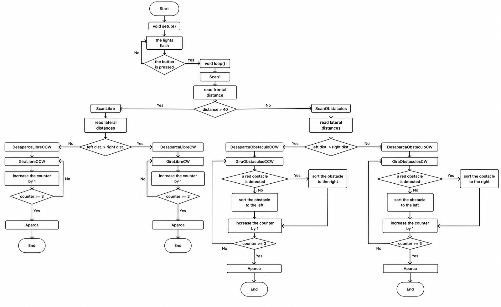
🎛️ Finite-State Machine Diagram
Here is a FSM that will show you the logic our program follows:
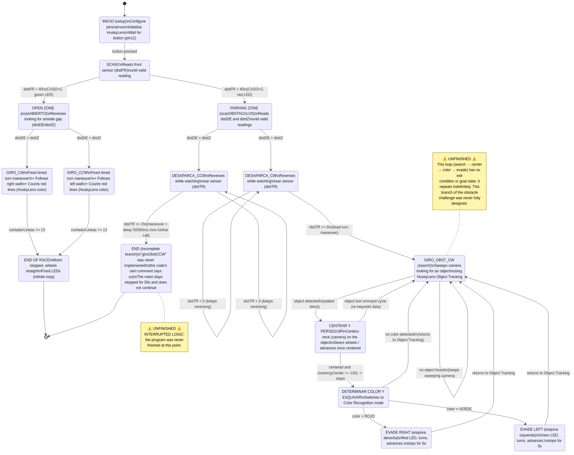
🔙 Previous versions
Here are all versions we did to make our final program:
* [SEGUIDOR_V1.00.ino](/src/Old_programs/Program_versions1/SEGUIDOR_V1.00.ino)
* [SEGUIDOR_V1.01.ino](/src/Old_programs/Program_versions1/SEGUIDOR_V1.01.ino)
* [SEGUIDOR_V1.02.ino](/src/Old_programs/Program_versions1/SEGUIDOR_V1.02.ino)
* [SEGUIDOR_V1.03.ino](/src/Old_programs/Program_versions1/SEGUIDOR_V1.03.ino)
* [SEGUIDOR_V1.04.ino](/src/Old_programs/Program_versions1/SEGUIDOR_V1.04.ino)
* [SEGUIDOR_V1.10.ino](/src/Old_programs/Program_versions1/SEGUIDOR_V1.10.ino)
* [SEGUIDOR_V1.11.ino](/src/Old_programs/Program_versions1/SEGUIDOR_V1.11.ino)
* [SEGUIDOR_V1.12.ino](/src/Old_programs/Program_versions1/SEGUIDOR_V1.12.ino)
* [SEGUIDOR_V1.20.ino](/src/Old_programs/Program_versions1/SEGUIDOR_V1.20.ino)
* [SEGUIDOR_V1.21.ino](/src/Old_programs/Program_versions1/SEGUIDOR_V1.21.ino)
* [SEGUIDOR_V1.22.ino](/src/Old_programs/Program_versions1/SEGUIDOR_V1.22.ino)
* [SEGUIDOR_V2.01.ino](/src/Old_programs/Program_versions1/SEGUIDOR_V2.01.ino)
* [SEGUIDOR_V2.02.ino](/src/Old_programs/Program_versions1/SEGUIDOR_V2.02.ino)
* [SEGUIDOR_V2.03.ino](/src/Old_programs/Program_versions1/SEGUIDOR_V2.03.ino)
* [SEGUIDOR_V2.04.ino](/src/Old_programs/Program_versions1/SEGUIDOR_V2.04.ino)
#### 8.2 Current programs (Raspberry - python)
📋 Test programs
These are all programs we used to calibrate sensors and conduct functional tests:
* [01.Blink_led.txt](/src/Current_programs/Test_programs2/01.Blink_led.txt) ➜ to make an external LED connected to a Raspberry Pi Pico board blink using the MicroPython programming language
* [02.Botón+led.txt](/src/Current_programs/Test_programs2/02.Botón%20+%20led.txt) ➜ to turn on an external LED only when you hold down a pushbutton
* [03.Contador con TCRT5000.txt](/src/Current_programs/Test_programs2/03.Contador%20con%20TCRT5000.txt) ➜ to count the lines on the floor using a TCRT5000 infrared optical sensor
* [04.Control de servo con potenciómetro.txt](/src/Current_programs/Test_programs2/04.Control%20de%20servo%20con%20potenciómetro.txt) ➜ to calibrate the steering servo
* [05.Medir distancia con TOF 400F.txt](/src/Current_programs/Test_programs2/05.Medir%20distancia%20con%20TOF%20400F.txt) ➜ to test the TOF400F laser sensor
* [06.Medir distancia con TFmini-s usand.txt](/src/Current_programs/Test_programs2/06.Medir%20distancia%20con%20TFmini-s%20usand.txt) ➜ to test the TFmini-S laser sensor
* [07.Leer color con TCS34725.txt](/src/Current_programs/Test_programs2/07.Leer%20color%20con%20TCS34725.txt) ➜ to read color values from the TCS34725 sensor using I2C
* [08.Contador con TCS34725.txt](/src/Current_programs/Test_programs2/08.Contador%20con%20TCS34725.txt) ➜ to count the lines on the floor using the TCS34725 digital color sensor
* [09.Leer escala de grises con TCRT500.txt](/src/Current_programs/Test_programs2/09.Leer%20escala%20de%20grises%20con%20TCRT500.txt) ➜ to verify the accuracy of the TCRT5000 sensor's grayscale reading by using it to distinguish colors (Conclusion: it is not reliable)
* [10.Conexion inicial con Husky1.txt](/src/Current_programs/Test_programs2/10.Conexion%20inicial%20con%20Husky1.txt) ➜ to verify the connection between the Raspberry Pi and HUSKLENS using the I2C communication protocol
* [11.Color Recognition con HUSKY.txt](/src/Current_programs/Test_programs2/11.Color%20Recognition%20con%20HUSKY.txt) ➜ to turn on two LEDs based on HuskyLens's visual object recognition
* [12.Calibrate the magnetometer 10DOF.py](/src/Current_programs/Test_programs2/12.calibrar_magnetometro.py) ➜ so that the robot knows which angle corresponds to each street
💻 Final program
This is our (almost) current final program (we are still working on it), that will be shown up on the WRO final:
[ANDORRA_V8](/src/Current_programs/Program_versions2/ANDORRA_V8)
🔄 Flowchart
Here is a flowchart that will help you understand how our final program works.
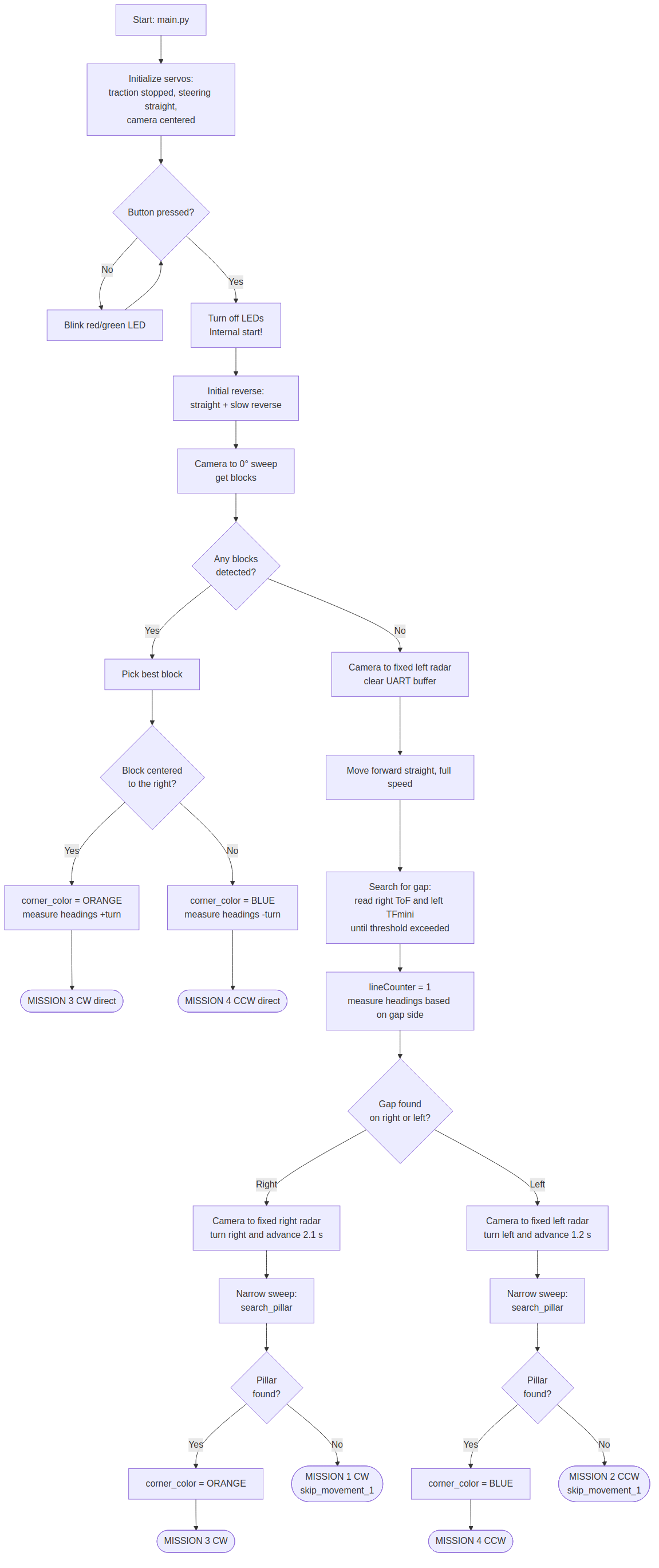
🎛️ Finite-State Machine Diagram
Here is a FSM that will show you the logic our program follows:
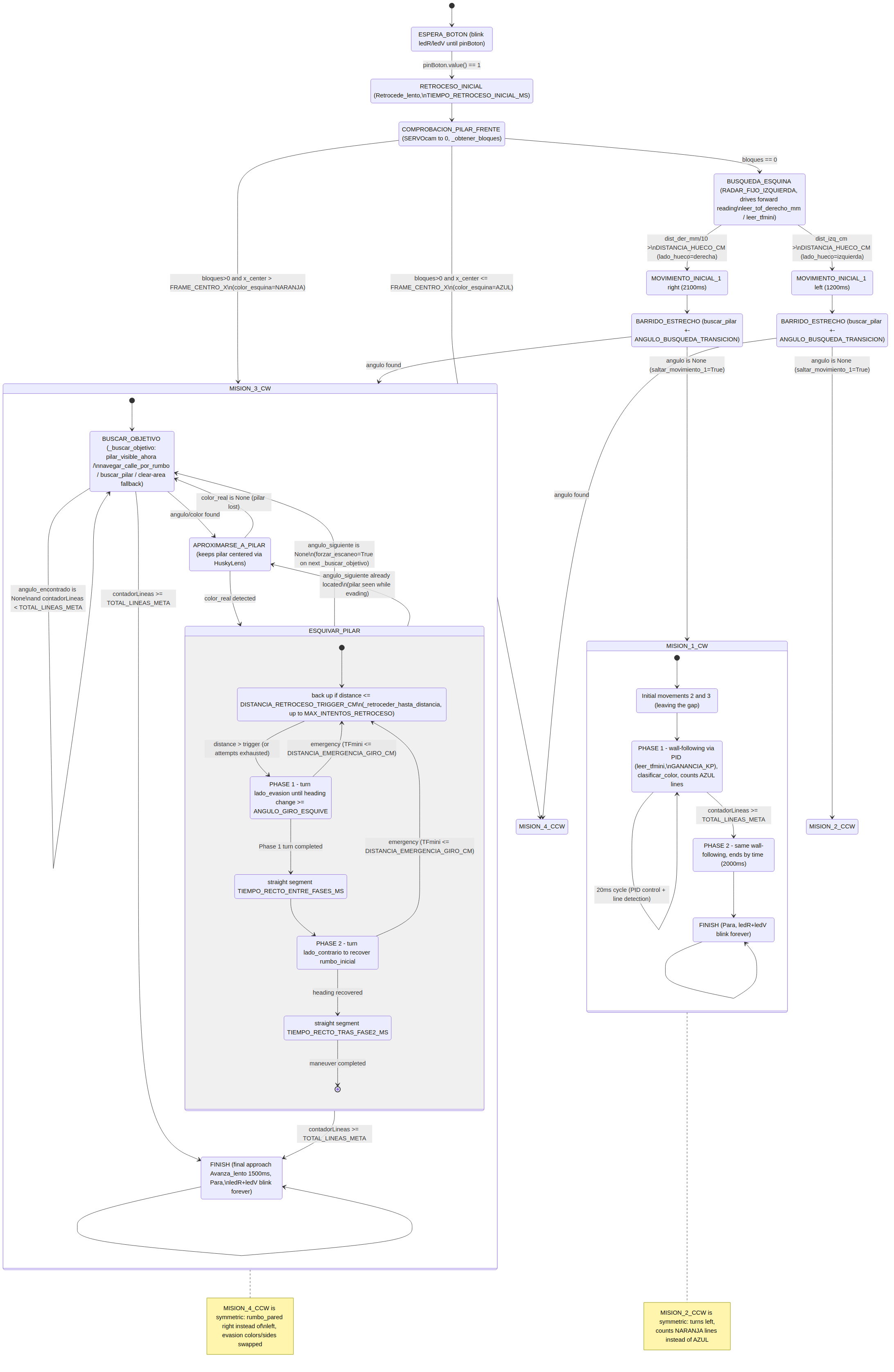
🔙 Previous versions
* [ANDORRA_V1](src/Current_programs/Program_versions2/ANDORRA_V1)
* [ANDORRA_V2](src/Current_programs/Program_versions2/ANDORRA_V2)
* [ANDORRA_V3](src/Current_programs/Program_versions2/ANDORRA_V3)
* [ANDORRA_V4](src/Current_programs/Program_versions2/ANDORRA_V4)
* [ANDORRA_V5](src/Current_programs/Program_versions2/ANDORRA_V5)
* [ANDORRA_V6](src/Current_programs/Program_versions2/ANDORRA_V6)
* [ANDORRA_V7](src/Current_programs/Program_versions2/ANDORRA_V7)
### 9. 🦾 Build our robot
Here you will find everything necessary to create our current robot step by step
9.1 Components
Here are all the necessary components:
| Component | Quantity | Preview | Main Function | Purchase link |
| :---: | :---: | :---: | :---: | :---: |
| SPT5632-360 | 1 | | Robot mobility | 🛒 Shop |
| MS18 | 1 | | Robot direction system | 🛒 Shop |
| TFmini-S | 1 | | Measure distances | 🛒 Shop |
| T0F400F | 2 | | Measure distances | 🛒 Shop |
| LED | 2 | | Checkpoints | 🛒 Shop |
| HUSKYLENS | 1 | | Object detection | 🛒 Shop |
| Raspberry pi pico 2 rp2350 | 1 | | Robot controller | 🛒 Shop |
| KS3017 Keyestudio Raspberry Pico IO Shield | 1 | | Conexions | 🛒 Shop |
| 10 DOF IMU sensor (L3GD20 - gyroscope) | 1 | | Robot orientation | 🛒 Shop |
| TCS34725 RGB sensor | 1 | | Lines detection | 🛒 Shop |
| Rocker Switch | 1 | | Power on and off robot switch | 🛒 Shop |
| Pull down button | 1 | | Starter robot program button | 🛒 Shop |
| Samsung battery 2600mAh | 4 | | Batteries | 🛒 Shop |
| Lego wheels 30,4x14 | 2 | | Directional wheels | 🛒 Shop |
| Lego wheels 13x24 | 2 | | Drive wheels | 🛒 Shop |
| Servo arm | 1 | | Servo direction arm | 🛒 Shop |
| Gear teeth Lego 4285634 | 1 | | Gear teeth transmission | 🛒 Shop|
| Lego structure piece 4495931 | 3 | | Maintain direction structure | 🛒 Shop |
| Lego structure piece 4210686 | 3 | | Connect directional wheels and connect them with the structure | 🛒 Shop |
| Lego piece 4514554 (3 modules) | 3 | | Connect the directional | 🛒 Shop |
| Lego piece 4514553 (3 modules) | 4 | | Connect the directional structure and connect it with chassis | 🛒 Shop |
| Lego piece 4211807 (2 modules) | 2 | | Connect the directional structure | 🛒 Shop |
| Lego piece 4495931 (2 modules) | 1 | | Connect directional structure | 🛒 Shop |
| Lego piece 4560175 | 1 | | Connect directional structure | 🛒 Shop |
| Lego piece 4107767 | 2 | | Connect directional wheels with directional structure | 🛒 Shop |
| Lego piece 4107085 | 2 | | Connect directional structure | 🛒 Shop |
| LM7805CT | 2 | | Supply energy to huskylens directly of the batteries | 🛒 Shop |
| Electrolytic condenser 0,1 microfarad | 1 | | (maker recommendation) | 🛒 Shop |
| Electrolytic condenser 0,33 microfarad | 1 | | (maker recommendation) | 🛒 Shop |
| Circuit board | 1 | | Connect huskylens with the LM7805CT and then with batteries | 🛒 Shop |
| Differential QBX01 1:12 | 1 | | It allows the drive wheels to rotate at different speeds on curves, preventing slippage | 🛒 Shop |
| Power Expansion Board Module | 2 | | It's a type of power bank where we've used the same Samsung batteries | 🛒 Shop |
| Micro Servo MG90S | 1 | | Allow the camera to move and have a wider field of view | 🛒 Shop |"> Camera servo link |
| Heatsink | 1 | | Prevent the current regulator from overheating | 🛒 Shop |
| USB-Kabel | 1 | | It makes it easy to connect the robot to the computer to upload programmes or view the terminal when we’re carrying out tests, in a simple and convenient way that prevents the Raspberry Pi’s connector from breaking. | 🛒 Shop |
| Chasis in 3D | 1 | | Skeleton of the robot | [`📥Download`](models/CHASIS_modificado_2.stl) |
| Battery support 1 | 2 | | Support batteries | [`📥Download`](models/soportebateria1.stl) |
| Battery support 2 | 1 | | Support batteries | [`📥Download`](models/soportebateria2.stl) |
| Switch support | 1 | | Support the switch | [`📥Download`](models/SOPORTE_INTERRUPTOR.stl) |
| Adapter wheels in 3D | 2 | | Supply energy to huskylens directly of the batteries | [`📥Download`](models/wheel%20adapter.stl) |
| Adapter gear in 3D | 1 | | Gearing with 360º servo gear | [`📥Download`](models/GEAR_ADAPTER.stl) |
| Magnetometer mast | 1 | | Support the magnetometer | [`📥Download`](models/SOPORTE_10-DOF.stl) |
9.2 Pins connections
Use these two photos to connect the components:
9.3 Placing
Here you will find two files showing the exact position of each component:
9.4 Raspberry pi pico 2 and VSCode startup
Firmware of the Raspberry Pi Pico 2➜ First of all, you’ll need to install a firmware on the Raspberry Pi Pico 2 so that we can load programmes onto it and use it in VScode. You can find the firmware on the official website MicroPython for Raspberry Pi Pico 2, download it here. We’ll explain how to do this step by:
*Press and hold the white BOOTSEL button on your Raspberry Pi Pico 2 board; without letting go, connect the board to your computer using a compatible USB cable. Release the button once the computer has recognised the card. It will appear as an external USB storage device.
*Drag and drop (or copy and paste) the .uf2 file you downloaded directly onto the Pico 2’s USB drive. The board will restart automatically and the device will disappear from your computer. This means that the firmware has now been installed.
*Here you can install VScode
9.5 Adjust the servos
Here you will find the essential software for calibrating servos and sensors, so that you can get the robot ready and load the final programme onto it.
* [01.Calibrate the steering servo.txt](/src/Current_programs/Test_programs2/04.Control%20de%20servo%20con%20potenciómetro.txt) ➜ One of the first things you need to do to get your robot working is to calibrate the steering servo. First, upload this programme to the servo, and use a potentiometer to adjust the servo until it stops at 90 degrees. This programme can also be used to calibrate the servo attached to the HUSKYLENS.
* [02.Calibrate the magnetometer 10DOF.py](/src/Current_programs/Test_programs2/12.calibrar_magnetometro.py) ➜To guide you through the circuit’s streets, you’ll first need to calibrate the magnetometer; to do this, we’ll load this programme onto the Raspberry Pi. Calibration involves placing the robot on the circuit. You must remove or move as far away as possible any metal objects in the vicinity, as these may interfere with the calibration. After that, you must rotate the robot around an imaginary axis and turn it as many times as necessary until the offset_x and offset_y values stabilise and remain constant. You will be able to monitor all of this on the terminal.
* [03.Calibrate the magnetometer 10DOF.py](/src/Current_programs/Test_programs2/13.lsm303_mag)➜This is the magnetometer library. Once the magnetometer has been calibrated, make a note of the offset_x and offset_y values, as you will then need to enter these values next to where it says OFFSET_X_DEFAULT and OFFSET_y_DEFAULT. There may already be some values in the library we’ve uploaded; change them and enter the ones you’ve calculated, as those were our offset values, yours will be different.
We’re almost there, all that’s left is for you to save the red and green colours in the HUSKYLENS, with red as colour ID1 and green as colour ID2. It’s very simple and will only take a couple of minutes.
And that’s it, you can now load the final programme, along with its sub-programmes, onto it and get your robot up and running!!!😀
⬆️Back to top