# WRO 2026 — Future Engineers | Self-Driving Car
> **Team:** FoxRobotics
> **| Members:** Erick Blanco · Jesse Banda · César Emiliano Ahumada
> **| Coach:** Daniel Millan
> **| Country / Region:** México — Baja California
> **| Season:** 2026
---
## Table of Contents
1. [Vehicle Overview](#1-vehicle-overview)
- [1.1 Design goals](#11-design-goals) · [1.2 Bill of Materials](#12-bill-of-materials) · [1.3 What changed in v2](#13-what-changed-for-the-international-final-v2)
2. [Mechanical Design & Mobility](#2-mechanical-design--mobility)
- [2.1 Chassis selection](#21-chassis-selection) · [2.2 Wheels](#22-wheels) · [2.3 Drive system (torque vs. speed)](#23-drive-system-torque-vs-speed-analysis) · [2.4 Steering](#24-steering--rack-and-pinion-with-ackermann-geometry) · [2.5 Custom parts & assembly](#25-custom-parts--assembly) · [2.6 v2 chassis](#26-v2-chassis--shorter-car-pi-on-top)
3. [Power Architecture & Sensors](#3-power-architecture--sensors)
- [3.1 Power budget](#31-power-budget) · [3.2 Sensor selection and placement](#32-sensor-selection-and-placement) · [3.3 PCB & wiring](#33-pcb--wiring) · [3.4 Raspberry Pi 5](#34-main-computer--raspberry-pi-5-v2)
4. [Software Architecture](#4-software-architecture)
- [4.1 System overview](#41-system-overview--two-controllers-one-link) · [4.2 Inter-controller protocol ("V2")](#42-inter-controller-protocol-v2) · [4.3 Vision pipeline](#43-vision-pipeline-raspberry-pi--pure_pursuit) · [4.4 Obstacle handling](#44-obstacle-handling-obstacle-challenge) · [4.5 ESP32 state machine](#45-esp32-finite-state-machine-srcesp32purepursuitpurepursuitino) · [4.6 Cascade PID](#46-cascade-pid-always-running-underneath) · [4.7 Startup handshake](#47-startup-handshake) · [4.8 Development status](#48-development-status)
5. [Systemic Thinking & Engineering Decisions](#5-systemic-thinking--engineering-decisions)
- [5.0 Design constraints](#50-design-constraints) · [5.1 Subsystem interaction map](#51-subsystem-interaction-map) · [5.2 Key engineering trade-offs](#52-key-engineering-trade-offs) · [5.3 Iteration log](#53-iteration-log) · [5.4 Risk analysis](#54-risk-analysis) · [5.5 Failure & Incident log](#55-failure--incident-log)
6. [Testing & Validation](#6-testing--validation)
- [6.1 How we test](#61-how-we-test) · [6.2 Results to date](#62-results-to-date) · [6.3 Validation matrix](#63-validation-matrix) · [6.4 Pre-run checklist](#64-pre-run-checklist-each-venue) · [6.5 Milestones](#65-milestones) · [6.6 Releases](#66-releases)
7. [How to Build & Run](#7-how-to-build--run)
- [7.1 Hardware](#71-hardware-requirements) · [7.2 ESP32 firmware](#72-esp32-firmware) · [7.3 Raspberry Pi software](#73-raspberry-pi-software) · [7.4 Calibration](#74-calibration-before-each-venue) · [7.5 Run](#75-run) · [7.6 Autostart & deployment](#76-autostart--deployment)
8. [Repository Structure](#8-repository-structure)
9. [Videos](#9-videos)
10. [Photos](#10-photos)
**Companion document:** [Engineering Journal](ENGINEERING_JOURNAL.md) — the dated, phase-by-phase build log, from the pre-repo design work through today, tied to commits. [§5.3 Iteration log](#53-iteration-log) and [§6.5 Milestones](#65-milestones) are the thematic views of the same history.
---
# 1. Vehicle Overview
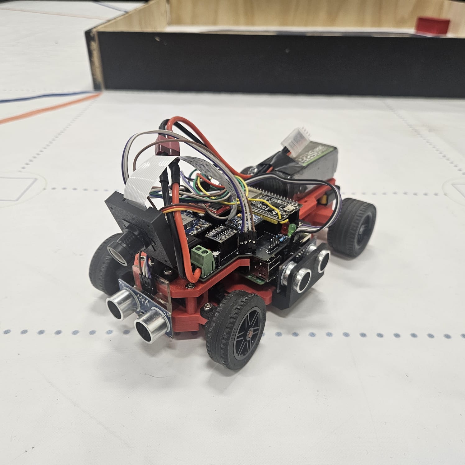
Our vehicle is a custom-built autonomous car for the WRO 2026 Future Engineers — Self-Driving Cars challenge. It completes 3 laps around a randomized track, and in the Obstacle Challenge it also detects and correctly passes coloured traffic-sign pillars (**red → keep the pillar on the car's left / pass on its right; green → keep it on the right / pass on its left**) before parking at the end.
The car uses **two controllers working together**: a Raspberry Pi runs the camera vision pipeline (a Raspberry Pi 4 at the national final, a Raspberry Pi 5 for the international final) and the high-level path planner (Pure Pursuit), and an ESP32 runs the real-time control loop, the state machine and all the actuators. They talk over a UART link with a small line-based protocol ("V2"). This split is the central architectural decision of the project and is explained in [Section 4](#4-software-architecture) and [Section 5](#5-systemic-thinking--engineering-decisions).
**Key specifications:**
| Parameter | Value |
|---|---|
| Dimensions | v1: 210 × 140 × 80 mm body, ≈240 mm overall with the extension added to drive out of the parking lot · v2: ≈170 × 130 × 110 mm (168.7 × 128 mm in CAD; height includes the camera ribbon over the top, §2.6) |
| Weight | 564 g |
| Drive type | Rear-wheel drive (RWD) |
| Steering | Ackermann rack-and-pinion, SG90 servo — v2: 53° inner / 37° outer wheel at full lock, ~106% Ackermann (§2.4) |
| High-level controller | Raspberry Pi 5, 16 GB + Active Cooler (vision + Pure Pursuit) — Raspberry Pi 4 Model B until the national final (§3.4) |
| Real-time controller | ESP32 DevKit (FSM, PID, motor & sensor I/O) |
| Inter-controller link | UART @ 115200 baud, line protocol "V2" (see §4.2) |
| Vision | Raspberry Pi Camera, NoIR wide-angle lens (FOV ≈ 120°), processed at 640 × 480; custom lens-shading calibration on the Pi 5 (ERR-03) |
| Distance sensors | HC-SR04 (5V) × 3 — left, right, front — via 5V↔3.3V level shifter · v2: + VL53L1X ToF × 4, in integration (§3.2) |
| IMU | MPU-6050 (gyroscope + accelerometer) · v2: BNO085 with on-chip sensor fusion, in integration (§3.2) |
| Drive motor | v1: N20 DC gear motor (50:1) · v2: Pololu 50:1 12 V gear motor **with encoder** · + 2:1 stage → 100:1 total |
| Motor driver | TB6612FNG |
| Battery | 3S LiPo 11.1 V 2200 mAh |
| Logic power | MINI560 step-down, 5 V |
## 1.1 Design goals
One reliable vehicle that finishes **both** challenges — scoring for completing three laps consistently over completing them fast. Everything below follows from that.
- **Fixed architecture from day one: Raspberry Pi 4 + ESP32.** The Pi does *all* image processing and vision; the ESP32 does *all* peripheral I/O — both sensing and actuation. This split was decided before the first line of code and never revisited.
- **Small footprint for maneuverability.** Comfortably inside the rulebook envelope with ~10 cm of margin on width and length — the car is ≈ 20 × 10 cm, deliberately smaller than the limit so it has room to maneuver in the obstacle field.
- **Mechanically extensible.** The chassis and the PCB were designed so components could be added later without a redesign. This paid off directly: the front ultrasonic — added for the obstacle-round segmented turn (see [§4.5](#45-esp32-finite-state-machine-srcesp32purepursuitpurepursuitino)) — went from idea to mounted-and-wired in under 30 minutes because both the chassis and the PCB already had the space and a spare header.
- **Tight-turn capable.** Rack-and-pinion steering driving both wheels symmetrically ([§2.4](#24-steering--rack-and-pinion-with-ackermann-geometry)) so the car can take the obstacle-round corners without a multi-point turn.
- **Room for a printed differential** so the rear wheels can turn at different speeds through a corner without scrub.
- **Electronics-first packaging.** The chassis was sized around the electronics — the Raspberry Pi 4 above all — and the PCB was then laid out to fit the finished mechanical model, not the other way around.
## 1.2 Bill of Materials
### Custom Manufactured Parts
| ID | Component | Description | Quantity | Supplier | Approximate Cost |
|---|---|---|---|---|---|
| 1 | BaseChasis | Main body of the vehicle. | 1 | Custom made, 3D printed | 1.6 USD |
| 2 | TopShell | Upper part of the vehicle. | 1 | Custom made, 3D printed | 1 USD |
| 3 | Cremallera | Rack used for steering. | 1 | Custom made, 3D printed | 0.1 USD |
| 4 | ServoGearDirection | Pinion for the steering system, directly connected to the servo. | 1 | Custom made, 3D printed | 0.5 USD |
| 5 | LinkageDirection | Linkage between the rack and steering knuckle. | 2 | Custom made, 3D printed | 0.05 USD |
| 6 | SteeringKnuckle | Allows lateral wheel movement for steering. | 2 | Custom made, 3D printed | 0.15 USD |
| 7 | DCsupport | Holds the DC motor in place. | 1 | Custom made, 3D printed | 0.05 USD |
| 8 | RingDifferential | Main driven gear of the differential that transfers power to the axle assembly. | 1 | Custom made, 3D printed | 0.25 USD |
| 9 | PlanetDifferential | Allows torque distribution between both wheels while enabling different wheel speeds during turns. | 2 | Custom made, 3D printed | 0.1 USD |
| 10 | PinionDifferential | Transfers rotational motion from the motor to the differential gear system. | 1 | Custom made, 3D printed | 0.1 USD |
| 11 | SunDifferential | Transfers torque from the differential gears to the wheel axle. | 2 | Custom made, 3D printed | 0.1 USD |
| 12 | CameraBase | Holds the camera frame in place. | 1 | Custom made, 3D printed | 0.1 USD |
| 13 | CameraBack | Rear section of the camera frame. Connects to the CameraBase. | 1 | Custom made, 3D printed | 0.1 USD |
| 14 | CameraFront | Camera frame. | 1 | Custom made, 3D printed | 0.2 USD |
| 15 | UltrasonicSupport | Holds an ultrasonic sensor in place (used for the left, right and front sensors). | 3 | Custom made, 3D printed | 0.3 USD |
---
### LEGO Components
| ID | Component | Description | Quantity | Supplier | Approximate Cost |
|---|---|---|---|---|---|
| 16 | Lego 6135494 | Front wheel axle. | 2 | LEGO | 0.8 USD |
| 17 | Lego 4535768 | Rear wheel axle. | 2 | LEGO | 1 USD |
| 18 | Lego 6121485 | Reduces friction on the rear wheels. | 2 | LEGO | 0.4 USD |
| 19 | Lego 4299389 | Rim for rear wheels. | 2 | LEGO | 1.2 USD |
| 20 | Lego 4184286 | Tires for rear wheels. | 2 | LEGO | 3.5 USD |
| 21 | Lego 6251174 | Rim for front wheels. | 2 | LEGO | 1.2 USD |
| 22 | Lego 6182551 | Tires for front wheels. | 2 | LEGO | 3.82 USD |
---
### Electronics
| ID | Component | Description | Quantity | Supplier | Approximate Cost |
|---|---|---|---|---|---|
| 23 | ESP32 | Real-time controller: sensor I/O, cascade PID, finite state machine, actuator PWM. | 1 | Unit Electronics | 8 USD |
| 24 | Raspberry Pi 5 (16 GB) + Active Cooler + M.2 HAT+ | High-level controller: computer vision and Pure Pursuit path planning. Replaced the Raspberry Pi 4 (60 USD) after the national final; price includes taxes and shipping. | 1 | Official reseller | 410 USD |
| 25 | Mini560 5V | Step-down regulators. v2 uses two: one only for the Raspberry Pi 5, one for the ESP32, servo and sensors (v1 had one for everything). | 2 | Amazon | 12 USD |
| 26 | BNO085 | 9-axis IMU with on-chip sensor fusion (heading at 100 Hz). Replaced the MPU-6050 (3 USD) in v2. | 1 | Local purchase | 27 USD (500 MXN) |
| 38 | VL53L1X | Laser time-of-flight distance sensors — front, left, right and rear (v2). | 4 | Local purchase | 27 USD total (500 MXN) |
| 27 | HC-SR04 | Ultrasonic distance sensors — left, right (wall following) and front (obstacle-round cornering). | 3 | Unit Electronics | 10.5 USD |
| 28 | Level Shifter | Logic-level converter for the 5 V HC-SR04 echo lines into the 3.3 V ESP32. | 1 | Unit Electronics | 7 USD |
| 29 | Driver TB6612FNG | Motor driver controlling speed and direction of the DC drive motor. | 1 | Unit Electronics | 5 USD |
| 30 | RaspiCamera V2 | Camera module used for computer vision. Came with both ribbon cables: 15-pin for the Raspberry Pi 4 and 22-to-15-pin for the Raspberry Pi 5. | 1 | Amazon | 10 USD |
| 31 | Custom PCB | Power distribution and all signal connections. v1: single board (5 USD); v2: two-floor board, in design — price pending. | 1 | JLCPCB | 5 USD (v1) |
---
### Power System
| ID | Component | Description | Quantity | Supplier | Approximate Cost |
|---|---|---|---|---|---|
| 32 | Ovonic 2200mAh 3S | 3-cell LiPo battery powering the robot's electronics and drive system. | 1 | E-Bay | 13 USD |
---
### Actuators
| ID | Component | Description | Quantity | Supplier | Approximate Cost |
|---|---|---|---|---|---|
| 33 | Pololu 50:1 12 V gear motor with encoder | Drive motor; the encoder measures speed and distance. Replaced the N20 50:1 (6 USD) in v2. | 1 | Pololu | 20 USD |
| 34 | SG90 Servo | Micro servo motor used for steering control. | 1 | Unit Electronics | 6 USD |
---
### Fasteners
| ID | Component | Description | Quantity | Supplier | Approximate Cost |
|---|---|---|---|---|---|
| 35 | M3 Screws | Used for structural assembly and component mounting. | 23 | Local Hardware Store | 1 USD |
| 36 | M3 Nuts | Used to secure structural and electronic components. | 1 | Local Hardware Store | 0.05 USD |
| 37 | M2 Nuts | Used to secure servo motor and servo pinion | 3 | Local Hardware Store | 0.15 USD |
### Total Estimated Cost
| Version | Total |
|---|---|
| v1 — national final | ~155 USD |
| v2 — international final | **~576 USD** + v2 PCB (pending) |
**Where the increase comes from:** +410 USD Raspberry Pi 5 bundle, +27 BNO085, +27 VL53L1X ×4, +20 encoder motor, +6 second regulator; −69 USD for the parts that left the car (Raspberry Pi 4, MPU-6050, N20). About 85% of the increase is the Raspberry Pi 5, justified by the profiling in [§3.4](#34-main-computer--raspberry-pi-5-v2): 40 fps vs ~15 fps, no thermal throttling.
## 1.3 What changed for the international final (v2)
After winning the national final (2026-09-19, release [`v1.0-nacional`](docs/releases.md)) we reworked the parts of the car that were limiting it. Each change has its own section with the numbers behind it.
| Area | v1 (national final) | v2 | Why | Details |
|---|---|---|---|---|
| Steering geometry | Anti-Ackermann: the outer wheel steered *more* than the inner one (39.5° inner / 42.8° outer) | Ackermann corrected: rack joints 43 → 47 mm apart, tie rods 18.13 mm | Both front wheels now roll around the same turning center instead of fighting each other | [2.4](#24-steering--rack-and-pinion-with-ackermann-geometry) |
| Steering pinion | Module 1, 14 teeth | Module 1, **19 teeth**; servo moved 2.5 mm away from the rack | Same servo travel moves the rack 36% further: ~37° → **53°** on the inner wheel (measured in CAD) | [2.4](#24-steering--rack-and-pinion-with-ackermann-geometry) |
| Main computer | Raspberry Pi 4 | **Raspberry Pi 5, 16 GB** + Active Cooler | The Pi 4 was compute-bound at 14–18 fps and hit thermal throttling at 84 °C; the Pi 5 runs the same pipeline at ~40 fps at 52 °C | [3.4](#34-main-computer--raspberry-pi-5-v2) |
| Chassis layout | ≈24 cm long; Raspberry Pi enclosed in the center; motor perpendicular to the rear axle (bevel gears) | **≈17 cm long**; battery in the center where the Pi was; Pi 5 on top, open to the air; motor parallel to the axle (spur gears, same 2:1) | Tighter turns and more room to dodge and park; the enclosed Pi overheated (84 °C, throttling) | [2.6](#26-v2-chassis--shorter-car-pi-on-top) |
| Distance sensing | 3 × HC-SR04 only | 3 × HC-SR04 **+** 4 × **VL53L1X** ToF (front, left, right, rear), cross-checked against each other | Each sensor type fails differently against the black walls: the ultrasonic gives phantom echoes, the ToF can lose a dark wall. Using both lets each one veto the other's known failure | [3.2](#why-both-ultrasonic-and-tof) |
| Drive motor | N20 50:1, open-loop | **Pololu 50:1 with encoder** (mounted; speed loop pending) | Maneuvers changed with battery voltage; the encoder gives measured speed and distance | [2.6](#26-v2-chassis--shorter-car-pi-on-top) |
| IMU | MPU-6050, gyro rate integrated on the ESP32 | **BNO085**, fused heading computed on the sensor (UART-RVC, 100 Hz) | Integrated heading was 6.5% low over a run and carried a −7.5° bias after every corner maneuver | [3.2](#bno085-imu-v2-in-integration) |
| Power | One 5 V regulator for everything | **Two** regulators: one only for the Raspberry Pi 5 | Servo current spikes must not sag the Pi's supply; the Pi 5 draws more | [3.1](#v2-power-budget) |
| PCB | One board | **Two-floor** board: power floor + logic floor (in design) | The shorter chassis has less area, and four ToF + BNO085 need new connectors | [3.3](#v2-pcb--two-floor-board-in-design) |
| Camera color | Fixed white-balance gains only (Pi 4) | Lens-shading table calibrated for our lens + gains, as a project tuning file | The new image processor of the Pi 5 showed a magenta ring at the frame edges, close to the pink parking walls and red pillars | [ERR-03](#err-03--wide-angle-noir-lens-put-a-red-cast-on-every-frame) |
| Documentation | One README | + [releases](docs/releases.md), [test record](docs/testing.md), [engineering log](docs/engineering-log.md) (ERR-10 onward) | One release per event; every failure tied to a run number and a commit | §6 |
---
# 2. Mechanical Design & Mobility
### 2.1 Chassis selection
The chassis was designed from scratch to fit all the components we needed for competition. We printed it in red and black SUNLU PLA on a Bambu Lab A1, keeping the structure as light as possible without sacrificing the rigidity the drivetrain and electronics require.
For wheel transmission shafts, we used LEGO axles throughout: part 6135494 for the front and part 4535768 for the rear. This wasn't an aesthetic choice — LEGO axles have much better dimensional consistency than fully printed shafts, which flex under load and cause alignment issues. We also added LEGO bushings (6121485) to the rear axle to cut down on friction between moving parts.
| Component | Material / Part | Purpose |
| ----------- | --------------- | ----------------------- |
| Chassis | SUNLU PLA | Main robot structure |
| Front Axles | LEGO 6135494 | Power transmission |
| Rear Axles | LEGO 4535768 | Rear drivetrain support |
| Bushings | LEGO 6121485 | Friction reduction |
| Printer | Bambu Lab A1 | Manufacturing process |
We used PLA because it prints fast, doesn't warp like ABS, and is stiff enough for indoor competition conditions. PETG has better impact resistance and ABS handles heat better, but neither of those properties matters much for a robot running on a flat mat indoors. What did matter was being able to iterate quickly and get consistent parts, and PLA delivered on both.
### 2.2 Wheels
We tested several wheel options before settling on LEGO parts. The rear wheels use rim 4299389 with tire 4184286, and the front uses rim 6251174 with tire 6182551. Both have a 43 mm outer diameter, which keeps the ride height even front to rear.
Since the drivetrain already uses LEGO axles, LEGO-compatible rims were the obvious fit — they mount directly without adapters, which removes a potential source of wobble at the wheel interface.
The 43 mm diameter was also validated against our motor RPM target. At our gear ratio, this diameter puts normal operation in the 40–70% PWM range, which gives us enough resolution for smooth speed control. A noticeably larger wheel would push operating duty cycles above 85% and compress the usable throttle range.
We ran the car at full throttle on the competition mat surface and saw no detectable slip at the rear. The LEGO rubber compound grips the white matte WRO field without any prep needed.
### 2.3 Drive system (torque vs. speed analysis)
The main drive is an N20 DC motor with a 50:1 internal gearbox — compact at 12 × 10 × 26 mm and still enough torque for a ~1.5 kg vehicle. Between the motor output shaft and the differential, we added a 2:1 LEGO gear stage, bringing the total drivetrain reduction to **100:1** and estimated rear axle torque to about 1.76 kg·cm.
**Why 100:1 and not just 50:1?**
We ran the 50:1 configuration first. It was faster, but corner exits were inconsistent — the rear wheels would occasionally lose traction under acceleration, causing yaw disturbances the PID couldn't fully catch. At 100:1, top speed dropped but torque delivery became smooth and predictable all the way through the speed range. Corner exits became repeatable, which turned out to be a prerequisite for reliable PID tuning.
The ratio also keeps the motor in its efficient RPM band during most of the run, which matters because the motor shares a power source with the logic rail.
The car completes all three Open Challenge laps in about 12 seconds at just 60% motor speed. That headroom is useful if we need to push speed in later iterations.
**The takeaway:** we prioritized consistency over raw speed. A robot that reliably finishes 3 laps scores more than one that's faster but unpredictable.
### 2.4 Steering — rack-and-pinion with Ackermann geometry
Steering is controlled by an SG90 servo connected to both front knuckles through a rack-and-pinion mechanism with symmetric tie rods.
**Mechanism specs (v1, national final):**
| Parameter | Value |
|---|---|
| Servo | SG90 (0°–180° range) |
| Firmware straight-ahead trim | 80° (servo-horn spline offset; `centroServo` in firmware) |
| Pinion | Module 1, 14 teeth |
| Pinion pitch diameter | 14 mm (dp = m × z = 1 × 14) |
| Pinion outer diameter | 16 mm (dp + 2×addendum = 14 + 2) |
| Rack | Module 1, 11 teeth, 27.5 mm total travel |
| Rack displacement per servo degree | 0.1222 mm/° |
| Transmission ratio | 2.50° servo : 1° wheel |
| Geometric wheel steering range | ±43° from center |
| Firmware-clamped servo command | 20°–150° (≈ ±35° usable at the wheel) |
**Kinematic analysis:**
The 14 mm pitch diameter gives a pitch circumference of 43.98 mm. Each degree of servo rotation moves the rack 0.1222 mm. At 90° per side from center, the rack travels 11.00 mm per side — producing ±43° at the front wheels.
The outer diameter of 16 mm confirms the module (d_outer = dp + 2×m = 14 + 2 = 16 mm).
The 2.50:1 ratio reduces steering sensitivity at the wheel, which gives the inner control loop finer resolution at its update rate. A lower ratio would make steering response too abrupt.
The firmware never commands the full mechanical range: `escribirServo()` is clamped to 20°–150° (about ±35° at the wheel) so a saturated control output can't drive the rack into its physical end stop. That still clears the tightest Open-Challenge corridor (600 mm) and the maneuvering the Obstacle Challenge needs.
**Why rack-and-pinion over a direct servo arm?**
A direct arm only controls one wheel directly. The opposite knuckle, linked by a fixed-length tie rod, gets an angle that's geometrically correct only at center — producing toe error everywhere else. The rack pushes both tie rods symmetrically, so both wheels get the right angle at every steering position. Combined with the Ackermann geometry of the knuckles, each wheel tracks its own correct turning radius. No lateral scrub, and steering response is linear across the full range.
#### v2 redesign (October 2026) — Ackermann fix and a bigger pinion
In v2 we redesigned this mechanism because of two problems: the geometry was **anti-Ackermann**, and the car **could not turn tightly enough**. We simulated the linkage in Python with the exact CAD dimensions (the model matched the CAD within ~1°) before reprinting anything.
**Geometry reference** (top view, wheels straight, measured in SolidWorks):
| Parameter | Value |
|---|---|
| Kingpin track T (distance between the two knuckle pivots) | 60 mm |
| Wheelbase L (front kingpin line → rear axle) | 112.85 mm |
| Knuckle steering arm (pivot → tie-rod joint) | 12.49 mm, pointing ~43° outward and backward |
| Rack joints behind the kingpin line | 18.94 mm |
| Servo swing actually used | ±71° (measured from the rack travel, not the nominal ±90°) |
##### Problem 1 — anti-Ackermann (fixed)
In a turn, the inner wheel follows a smaller circle than the outer wheel, so it must steer **more**. Correct (100%) Ackermann is reached when
**cot(δ_outer) − cot(δ_inner) = T / L = 0.532**
and the axis lines of both front wheels cross on the rear axle line.
In v1 the rack joints were only 28.5 mm apart with 26 mm tie rods. We simulated the linkage in Python with the exact CAD dimensions, and the model matched the CAD within ~1°. At full travel the car steered **39.5° on the inner wheel and 42.8° on the outer wheel**: the outer wheel was steering *more* than the inner one. The two front wheels were trying to turn around different centers, so one of them always dragged sideways. That cost traction and current in every corner, and the car turned wider than the servo command implied.
Because the knuckles had to stay as they were (a new knuckle means a new arm, and the rack position is fixed by the chassis), we only changed **the spacing between the rack joints** and **the tie-rod length**. Those two values must change together: for the wheels to point straight with the rack centered, the tie rod must be
**linkage = √( (38.66 − spacing/2)² + 9.94² )** (mm, center to center)
| Rack joint spacing | Tie rod | Ackermann at 30° | 40° | 45° | 50° | 55° |
|---|---|---|---|---|---|---|
| 28.5 (v1) | 26.0 | anti-Ackermann | | | | |
| 43.0 (intermediate) | 19.83 | 51% | 62% | 69% | 76% | 84% |
| **47.0 (v2)** | **18.13** | 76% | **89%** | **95%** | **102%** | 110% |
| 50.0 | 16.89 | 99% | 111% | 117% | 124% | 131% |
*(Percentage = how much of the ideal inner/outer difference the linkage achieves. Below 100% the outer wheel steers slightly too much; above 100% it steers too little.)*
**Why 47 mm:** with a fixed knuckle, Ackermann cannot be exact over the whole range, because the percentage grows as the wheels turn. We chose the spacing that is closest to 100% in the 40°–50° range, which is where the car actually turns at corners and during parking. At small angles the error is under 0.7°, so it does not matter there. Each 0.1 mm of tie-rod error toes a wheel by ~0.5°, so the printed linkages are trimmed in 0.05–0.1 mm steps until the wheels are straight.
##### Problem 2 — turning radius (bigger pinion)
The steering angle depends almost only on **how far the rack moves**, and with the v1 pinion that was **±8.7 mm**: only ~37° on the inner wheel. We looked at three options: shorter knuckle arms, moving the rack, and a bigger pinion. The bigger pinion was the only one that needed no new chassis or knuckles.
| | v1 | **v2** |
|---|---|---|
| Pinion | Module 1, 14 teeth | **Module 1, 19 teeth** (20° pressure angle) |
| Pitch / outer diameter | 14 / 16 mm | **19 / 21 mm** |
| Rack travel per servo degree | 0.122 mm/° | **0.166 mm/°** |
| Rack travel at ±71° servo | ±8.7 mm | **±11.8 mm** |
| Inner / outer wheel at full lock | ~37° / ~32° (with 43 mm spacing) | **53.1° / 37.0°** (measured in the CAD assembly; the linkage model predicted ~50° / ~37°) |
| Turning radius at the rear-axle center (L / tan δ_inner + T/2) | ~208 mm (v1: 147 mm wheelbase, 39.5°) | **~115 mm** (v2: 113 mm wheelbase) — −45% |
| Ackermann at full lock | anti-Ackermann | **~106%** (ideal outer for 53.1° inner = 37.9°, measured 37.0°) |
- **Servo position.** The pitch radius grows from 7 to 9.5 mm, so the servo axis moved **2.5 mm away from the rack** with a spacer on its mount. The rack and the tie-rod joints stay at the same height, so the linkage geometry above is not affected.
- **Pinion profile.** We generated the involute tooth profile with our own script ([`Mecanica/Engranes/gen_pinon.py`](Mecanica/Engranes/gen_pinon.py)) and exported it as a single closed DXF contour that we extrude in SolidWorks. It includes 0.10 mm of backlash for 3D printing.
- **Toggle limit.** The linkage would lock (arm and tie rod aligned) at around 16 mm of rack travel. If the servo ever reached a true ±90°, the 19-tooth pinion could push the rack to ±14.9 mm. The intended mechanical stop is the knuckle touching the chassis before that point, and the servo output is also clamped in software.
- **Servo load.** The bigger pinion needs ~1.36× more servo torque for the same rack force. It also loses some angular resolution, which is still fine for an SG90 in a 0.5 kg car. The servo must not be left stalled against the stop, because it heats up and drags down the 5 V rail.
**Servo calibration.** The servo-to-wheel relation is no longer linear: near full lock the wheels turn faster per servo degree. The servo map and the steering gains in the ESP32 firmware are recalibrated on the assembled car (pending).
### 2.5 Custom parts & assembly
Every structural part is 3D-printed in SUNLU PLA on a Bambu Lab A1. The mechanical model was built first; the PCB was then laid out to fit it. Editable SolidWorks parts are in [`models/CAD/`](models/CAD/), printable meshes in [`models/STL/`](models/STL/), isometric renders in [`models/renders/`](models/renders/).
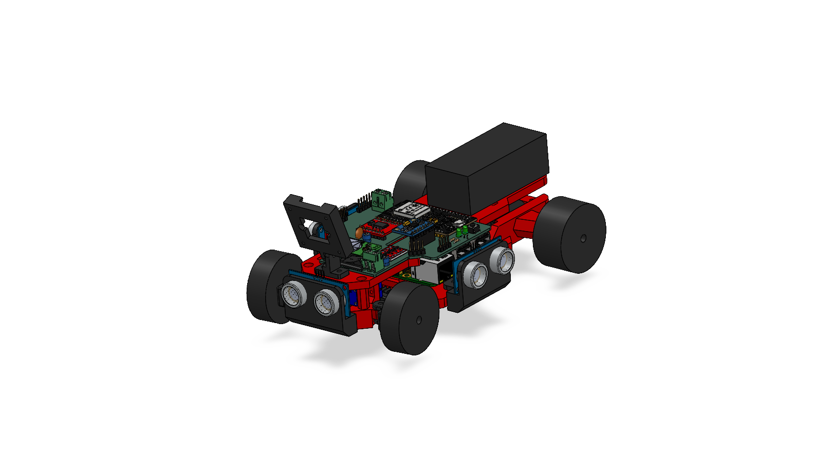
| Render | Part | Function / design note |
|---|---|---|
| 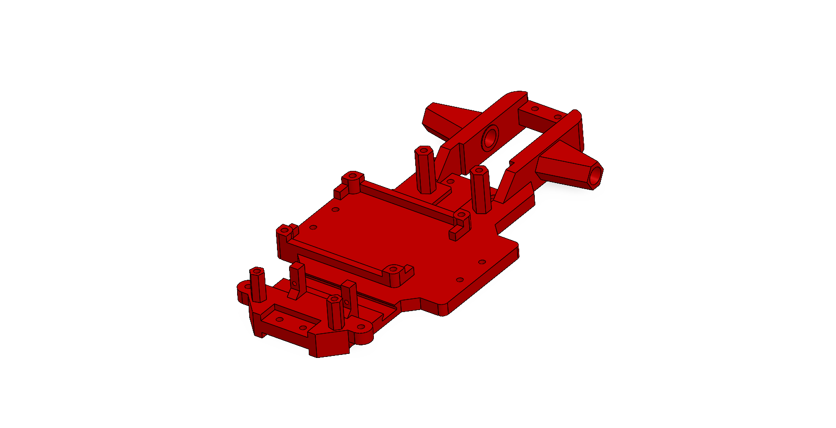 | **BaseChasis** | Main structure. Sized around the electronics (Raspberry Pi 4 first); carries the PCB, steering, drivetrain and every sensor mount. |
|
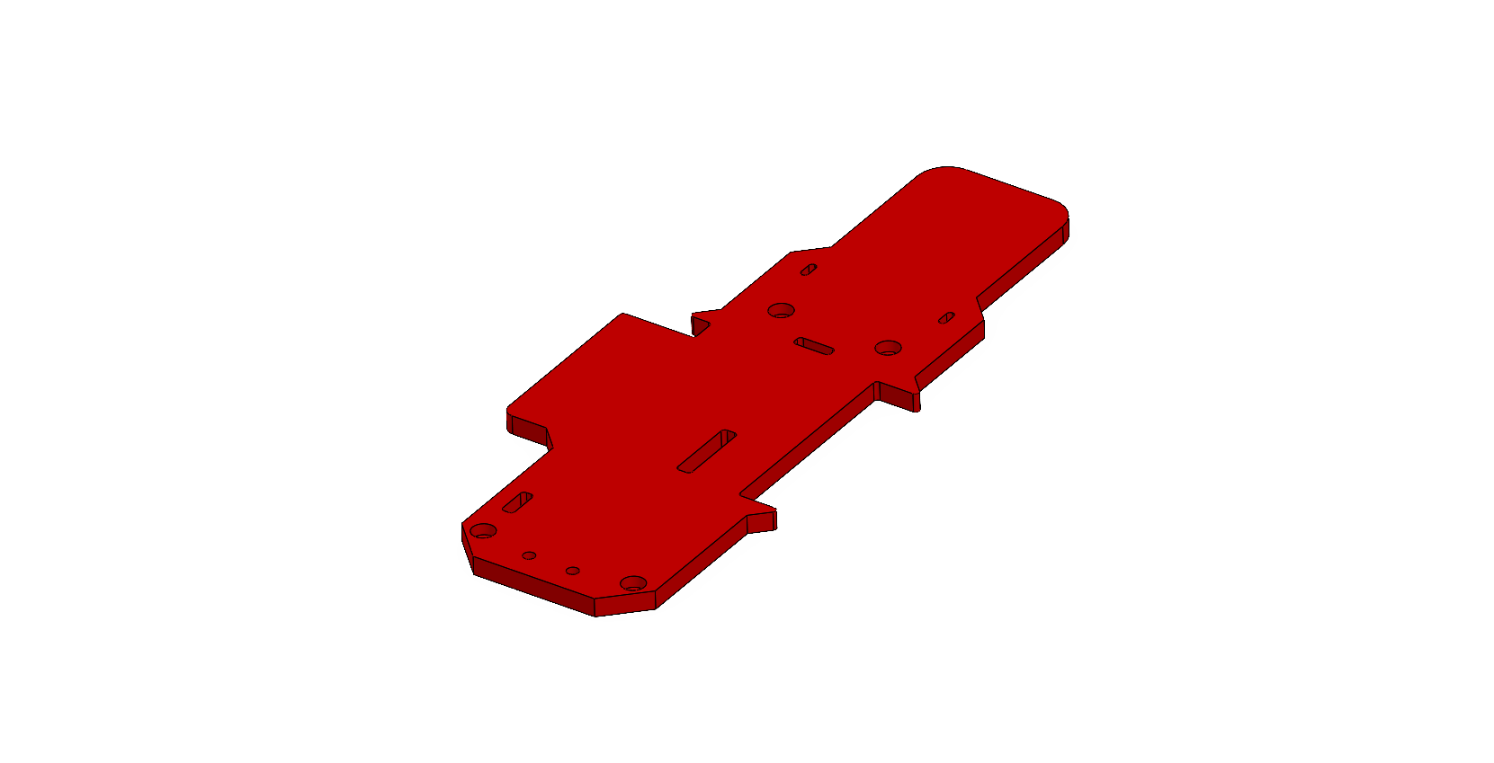 | **TopShell** | Top cover — closes the electronics bay and protects the wiring. |
|
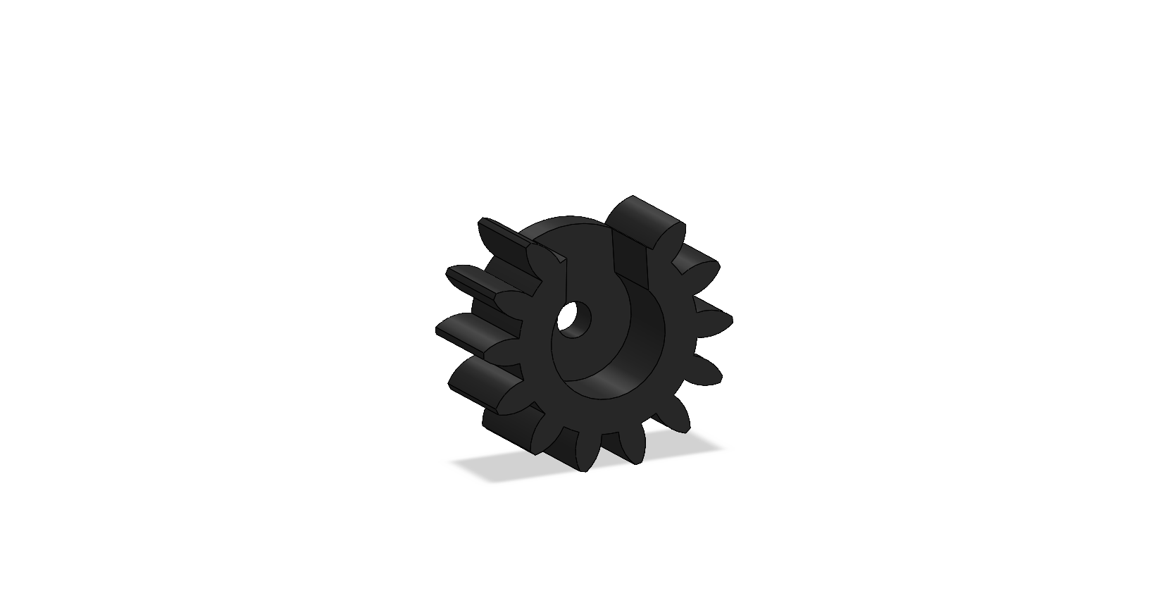 | **ServoGearDirection** | Pinion pressed onto the SG90 output shaft — module 1, 14 teeth (19 teeth in v2, [§2.4](#24-steering--rack-and-pinion-with-ackermann-geometry); profile generated by [`Mecanica/Engranes/gen_pinon.py`](Mecanica/Engranes/gen_pinon.py)). |
|
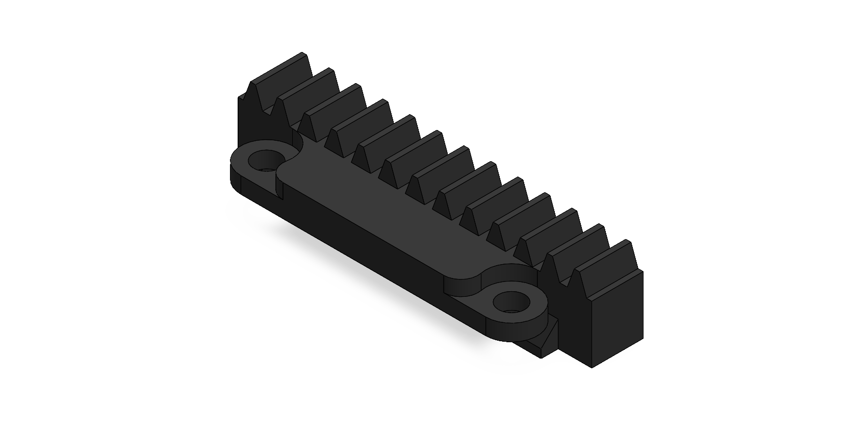 | **Cremallera** (rack) | Module 1, 11 teeth, 27.5 mm travel. Converts servo rotation into lateral travel for the tie rods. |
|
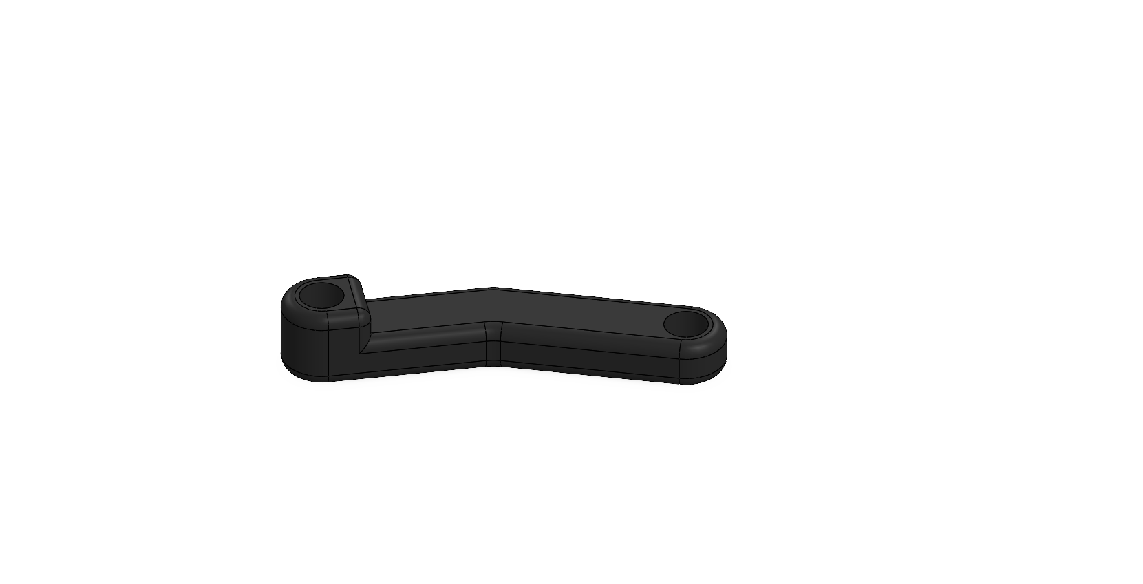 | **LinkageDirection** ×2 | Tie rods from the rack ends to the steering knuckles — symmetric, so both wheels get the correct angle at every rack position. |
|
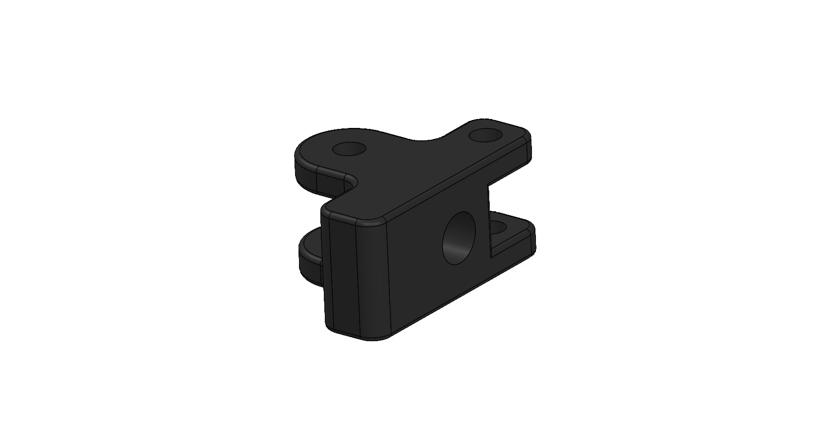 | **SteeringKnuckle** ×2 | Front-wheel pivots; their geometry sets the Ackermann steering angles. |
|
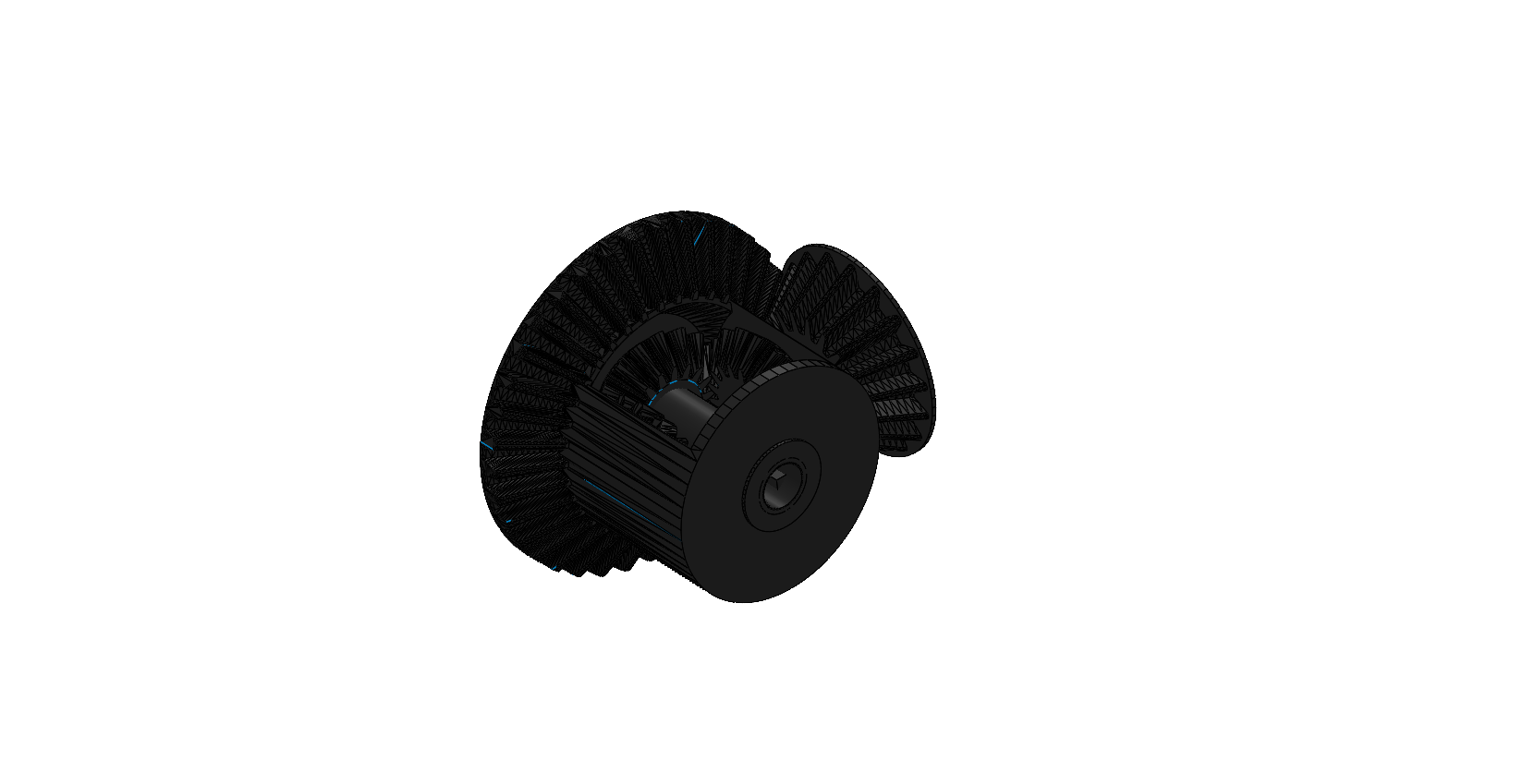 | **Differential** (Ring / Planet ×2 / Pinion / Sun) | Printed open differential — lets the rear wheels turn at different speeds through a corner. |
|
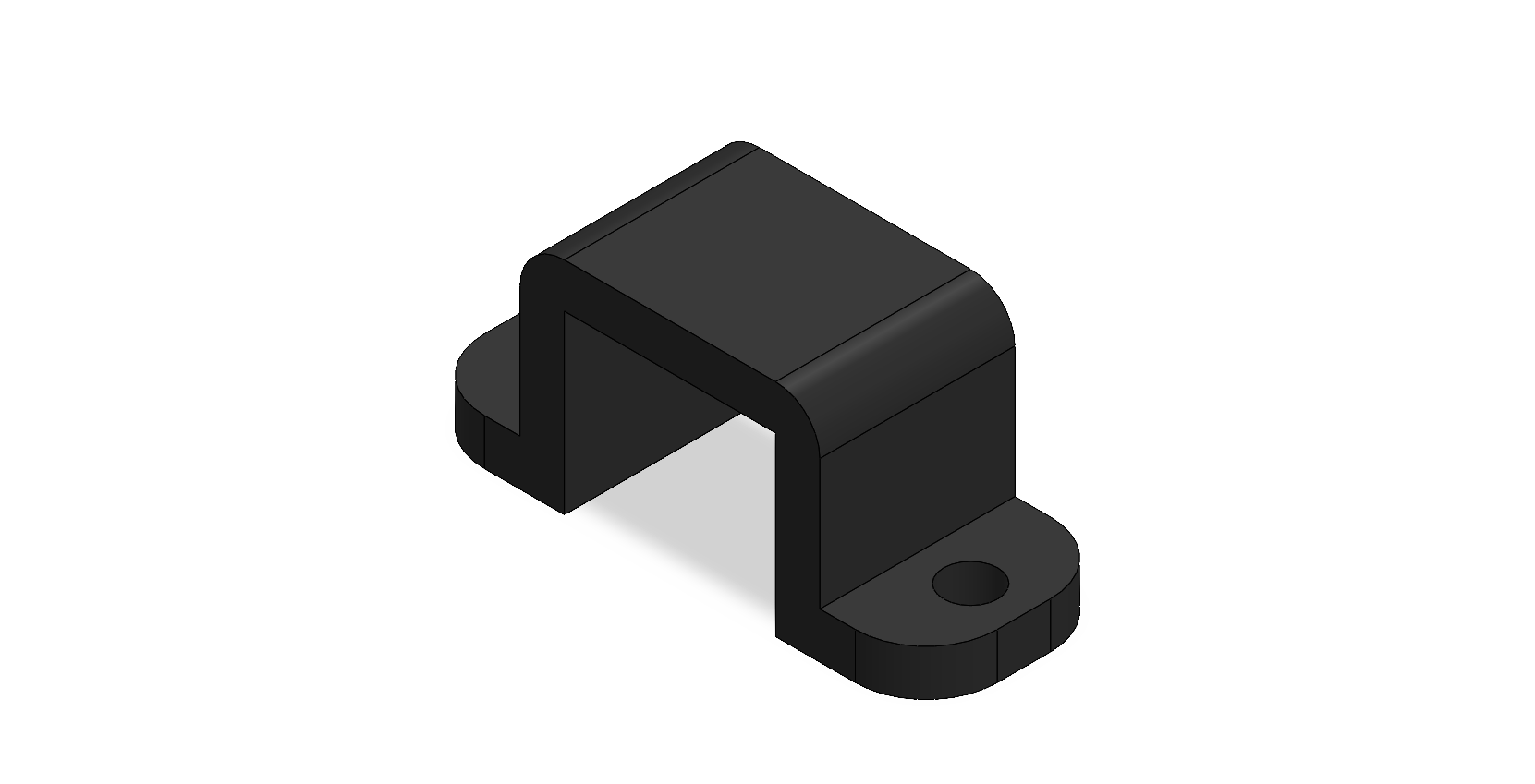 | **DCsupport** | Mounts the N20 gear motor to the chassis. |
|
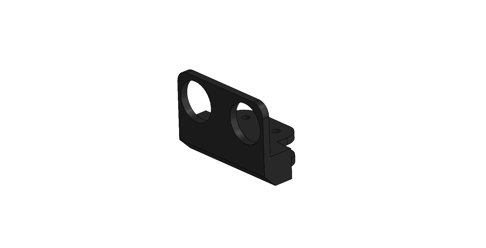 | **UltrasonicSupport** ×3 | Two identical side mounts; one slightly smaller front mount, added later for the obstacle-round segmented turn. |
|
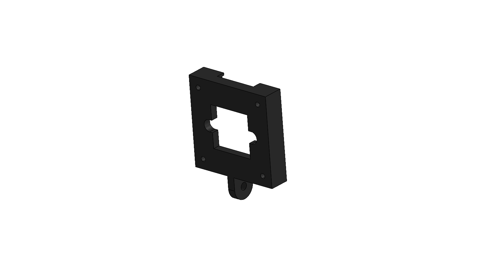 | **CameraHold** | Structure in charge of holding the camera. Sets the fixed ~20° downward tilt the BEV homography is calibrated against ([§3.2](#32-sensor-selection-and-placement)). |
#### Assembly order
1. **Chassis base** — the reference part everything mounts to.
2. **Steering** — press the pinion onto the servo and seat the servo in the chassis; slide in the rack; link each rack end to a SteeringKnuckle with a LinkageDirection tie rod; fit the knuckles and the front LEGO axles.
3. **Drivetrain** — N20 motor into the DCsupport; assemble the printed differential; rear LEGO axles with bushings.
4. **Sensor mounts** — the two side UltrasonicSupports (identical) and the smaller front one; the camera cage (base + back + front) with the camera.
5. **Electronics** — PCB onto the chassis bosses; wire the Pi 4, ESP32, the three HC-SR04 (through the level shifter), the MPU-6050, the TB6612 + motor, the servo, and the start button + status LED.
6. **TopShell** — close the bay.
All fasteners are M3 (M2 nuts on the servo horn and pinion).
### 2.6 v2 chassis — shorter car, Pi on top
*Status: designed in SolidWorks, being printed. Final dimensions and weight will be measured on the printed car.*
For the international final we rebuilt the chassis around two problems we kept seeing at the national final:
1. **The car was long for the obstacle field.** The body was 210 mm, but it reached ≈24 cm overall with an extension we added so the car could drive out of the parking lot comfortably. At that length every dodge swept a lot of floor, and the parking maneuver had little room in the lot.
2. **The Raspberry Pi overheated.** It sat enclosed in the middle of the chassis. With the remote-view client running it reached **84 °C** and throttled its CPU ([ERR-27](docs/engineering-log.md#err-27--the-remote-desktop-client-overheated-the-pi-4)), which lowered the vision frame rate.
**What we changed**
| Change | How | Why |
|---|---|---|
| **Motor parallel to the rear axle** | The drive motor now lies along the axle and drives the differential through **spur gears** (module 1, 15-tooth pinion on the motor's D-shaft, 30-tooth ring on the differential) instead of the perpendicular bevel pair | A motor perpendicular to the axle adds its whole length to the car. Lying along the axle, it adds almost nothing. |
| **Battery in the center** | The 3S pack sits crosswise in a side-loading tunnel, in the space the Raspberry Pi used to take | The heaviest part ends up in the middle and low, which balances the load front to rear. The side tunnel makes battery swaps quick. |
| **Raspberry Pi 5 on top** | The Pi moves from the enclosed center bay to the top of the car | The Active Cooler needs free air. Enclosed, the Pi recirculated its own hot air. On top, it also stays reachable for the camera cable and the SSD. |
| **Encoder motor** | Pololu 50:1 12 V gear motor with a quadrature encoder replaces the plain N20; same 50:1 ratio | Motor speed is open-loop today, so maneuvers change with battery voltage ([ERR-11](docs/engineering-log.md#err-11--a-fresh-battery-over-rotates-the-dodges)). The encoder lets the ESP32 hold a speed and measure distance, as the rules' reference build suggests. *Mounted; firmware integration pending.* |
| **Overall length ≈24 cm → ≈17 cm** (width 128 mm) | Result of the changes above | See below |
**Why a shorter car turns tighter.** For Ackermann steering, the radius of the path at the center of the rear axle is
**R = L / tan(δ_inner) + T/2**
where L is the wheelbase and T the kingpin track (60 mm). Shortening L shrinks R directly, at the same steering angle. With the v2 steering (53° inner wheel, [§2.4](#24-steering--rack-and-pinion-with-ackermann-geometry)) and the v2 wheelbase of **≈113 mm** (CAD), R ≈ **115 mm**. The v1 car had a wheelbase of ≈147 mm (measured) and ~40° of steering, so R ≈ **208 mm**. The turning radius is therefore **≈45% smaller**: about half from the shorter wheelbase, about half from the bigger steering angle. A smaller radius means a dodge needs less lateral room, the stop-and-turn corner maneuver needs less space ahead of the front wall, and the car fits the parking lot with more margin.
**The drivetrain keeps its ratio.** The old bevel pair was 36:18 = 2:1, and the new spur pair is 30:15 = 2:1. The total reduction stays at **100:1**, so the torque and speed analysis of [§2.3](#23-drive-system-torque-vs-speed-analysis) still holds. Spur gears are also easier to print accurately and to align than bevel gears. We checked the tooth strength with the Lewis bending equation (8 mm face, at the N20's stall torque): ≈5.7 MPa, roughly 9× below the strength of printed PLA. It is re-checked with the stall torque of the encoder motor. The gear center distance is designed at 22.6–22.7 mm (22.5 mm nominal) to leave printing clearance. The involute profiles are generated by our own script and exported as DXF; SolidWorks Standard has no gear generator.
**What stayed about the same, on purpose:** the height of the chassis, for stability in fast turns (the v2 car is ≈110 mm tall, but only the camera ribbon over the top reaches that); the LEGO axles and wheels ([§2.1](#21-chassis-selection), [§2.2](#22-wheels)); and the camera height and angle, so the bird's-eye-view calibration concept carries over (it is re-calibrated on the new mount).
---
# 3. Power Architecture & Sensors
### 3.1 Power budget
The whole vehicle runs off an Ovonic 2200mAh 3S LiPo. Power splits two ways: the motor driver takes battery voltage directly for the DC motor, and everything else goes through a MINI560 step-down converter producing a stable 5V at up to 5A.
| Rail | Source | Consumers | Max Current Draw |
|---|---|---|---|
| 5V Logic | MINI560 Step-Down Converter | Raspberry Pi 4 + RaspiCam V2, ESP32, HC-SR04 ×3, MPU6050, SG90 | ~4.0 A |
| Battery / Main Power | Ovonic 2200mAh 3S LiPo | Entire vehicle power distribution | ~35 A discharge capability |
| Motor Power | Motor Driver directly from 3S LiPo | DC drive motor | ~1.6 A peak |
| 3.3V Internal | ESP32 internal regulator | I²C communication and internal ESP32 logic, Level Shifter | ~200 mA |
The Ovonic battery is rated 120C continuous, which is theoretically 264 A. We're drawing about 4.5 A peak — under 2% of its discharge capability. There's no shortage of headroom here.
The Raspberry Pi and the ESP32 share the 5 V rail but the DC motor is fed straight from the battery through the TB6612FNG, so stall-current spikes on the motor never sag the logic supply.
#### v2 power budget
*Design values from the component datasheets and the Raspberry Pi documentation. Each rail will be measured with an inline meter on the assembled v2 car, and the measured values will replace these.*
The Raspberry Pi 5 draws more than the Pi 4 and is sensitive to voltage drops: when its supply sags it throttles the CPU, which directly lowers the vision frame rate. We already saw this on the Pi 4 when it was fed through Dupont jumpers (`throttled=0x50005`, CPU down to 600 MHz, [ERR-08](#err-08--raspberry-pi-undervoltage-from-undersized-power-wiring)). v2 therefore has **two 5 V regulators**: one only for the Raspberry Pi 5, and one for everything else. The servo's current spikes can no longer pull down the Pi's supply.
| Rail | Load | Typical | Design peak | Basis |
|---|---|---:|---:|---|
| **5 V-A** (Mini560 #1, 5 A) | Raspberry Pi 5 under vision load | 1.5 A | 2.5 A | 0.8 A bare-board active (Raspberry Pi docs) + 4 cores busy; peak covers load spikes |
| | Camera v2 | 0.25 A | 0.25 A | Camera module figure |
| | Active Cooler fan | 0.05 A | 0.1 A | Fan at full speed above 75 °C |
| | **Rail total** | **1.8 A** | **2.85 A** | 57% of the regulator's 5 A at peak |
| **5 V-B** (Mini560 #2, 5 A) | ESP32 (radio off) | 0.08 A | 0.25 A | Datasheet |
| | SG90 servo | 0.25 A | 0.70 A | Running current; peak = stall |
| | HC-SR04 × 3 | 0.045 A | 0.045 A | 15 mA each |
| | VL53L1X × 4 | 0.08 A | 0.16 A | ~20 mA each ranging, 40 mA peak |
| | BNO085 | 0.013 A | 0.013 A | Datasheet operating figure |
| | **Rail total** | **0.47 A** | **1.17 A** | 23% of the regulator at peak |
| **Battery 11.1 V** | Drive motor via TB6612 | — | 1.6 A | Peak measured on v1 (N20); to be re-measured with the encoder motor |
| **5 V-B** | Motor encoder | 0.01 A | 0.01 A | Hall-effect encoder |
**Battery current.** With ~90% regulator efficiency, the two 5 V rails at design peak draw 5 V × (2.85 + 1.17) A / 0.9 ≈ 22 W, which is ≈2.0 A from the 11.1 V pack. Adding the motor's 1.6 A gives **≈3.6 A worst case**. The 2200 mAh pack would last over 35 minutes even at that worst case, against a 3-minute round, so **capacity is not the constraint. Voltage is.** A freshly charged pack makes the motor ~17% stronger in low-PWM maneuvers ([ERR-11](docs/engineering-log.md#err-11--a-fresh-battery-over-rotates-the-dodges)), so we race inside an 11.70–12.15 V window.
**Heat.** At its typical 1.8 A, regulator #1 loses about 1 W at 90% efficiency. It is mounted in the airflow of the Pi on top of the car.
**Check before every session:** `vcgencmd get_throttled` must read `0x0` under full vision load.
### 3.2 Sensor selection and placement
| Sensor | Purpose | Placement | Notes |
|---|---|---|---|
| Raspberry Pi Camera Module V2 | Lane, corner-line and pillar detection | Front-center, ~20° downward tilt | Main vision system, OpenCV on the Pi |
| HC-SR04 (left) | Left wall distance | Left side of the chassis | Feeds the wall-centering PID |
| HC-SR04 (right) | Right wall distance | Right side of the chassis | Feeds the wall-centering PID |
| HC-SR04 (front) | Distance to the wall ahead when approaching a corner | Front bumper, facing forward | Obstacle round only — triggers the CRUCERO → MANIOBRA sequence |
| MPU-6050 *(v1)* | Heading integration during cornering and recovery | Center of chassis | Gyro Z integrated into `anguloGyro`, echoed back to the Pi |
| BNO085 *(v2, in integration)* | Fused heading at 100 Hz | Center of chassis, near the rotation axis | Replaces the MPU-6050; heading computed on the sensor |
| VL53L1X ToF ×4 *(v2, in integration)* | Near-field distance (≤ ~80 cm) with a software-set field of view | Front, left, right and rear, ~50 mm high | Cross-checked against the HC-SR04 — see [Why both](#why-both-ultrasonic-and-tof) |
#### Camera system
The camera handles lane geometry (via a bird's-eye-view transform), the orange corner-line markers, and red/green pillar detection. Image processing runs on the Raspberry Pi (Pi 4 → Pi 5 in v2) with OpenCV in real time and drives the Pure Pursuit planner.
It is mounted front-center with a ~20° downward tilt. We tested a horizontal mount first, but that captured too much background, which slowed detection and added noise. Tilting it down focuses the field of view on the track and the obstacle zone, which cut both false positives and computational load. The exact tilt is baked into the bird's-eye-view homography during calibration (see §4.3), so the mount must not move after calibration.
The lens is a wide-angle **NoIR** unit (~120° FOV), chosen over the original ~63° lens so the camera sees far enough ahead to react to a pillar and read the corner on the same frame. The wide lens ships without an IR-cut filter, which gave the raw image a heavy red cast and broke every HSV mask. The libcamera capture pipeline pins white-balance instead of letting it float — `libcamerasrc awb-enable=false colour-gains=<1.2,1.5>` — so the correction holds across venue lighting, and the pillar HSV ranges were re-tuned on the corrected image (see [ERR-03](#err-03--wide-angle-noir-lens-put-a-red-cast-on-every-frame)).
**v2 (Raspberry Pi 5):** fixed gains alone are not enough. The lens also needs its own **lens-shading table** (ALSC), otherwise the edges of the frame turn magenta. We calibrate that table from photos of a white sheet with the official Raspberry Pi tuning tool and ship it as a project tuning file, [`src/RASPI/cam/camera_tuning/`](src/RASPI/cam/camera_tuning/README.md). Result on a white sheet: R/G and B/G = 1.00 at the center **and** at all four corners (they were 1.3–1.4 at the corners).
#### HC-SR04 ultrasonic sensors
The left and right sensors drive lateral positioning and wall following. The **front** sensor was added for the Obstacle Challenge: because that round uses a segmented, stop-and-maneuver turn instead of a continuous arc (see §4.5), the car needs to know how far it is from the wall ahead so it can decide *when* to stop cruising and *which* maneuver (forward arc or reverse pivot) to run.
We originally tested VL53L0X time-of-flight sensors. On paper they win — ±3 mm accuracy versus ±15 mm for the HC-SR04, and a narrower beam. In practice, the black competition walls absorbed their 940 nm IR signal and consistently returned out-of-range readings at 300 mm. The HC-SR04 reflects off any surface regardless of color. We went with reliability over precision and made up the accuracy difference with software filtering (EMA on all three channels, plus a 5-sample median on the front channel to reject spikes before they can trigger a maneuver).
#### MPU-6050 IMU
The MPU-6050 gives heading and rotation data during cornering and recovery. The gyro Z axis is integrated each loop into `anguloGyro`, with a 1°/s deadband to suppress MEMS thermal drift on straights. On startup the firmware averages several hundred stationary samples to compute the gyro bias (`calcGyroOffsets`); if that offset comes back unusually large the firmware halves the integration scale as a safety net. The integrated heading is also sent back to the Pi in every acknowledgement so the vision side can dead-reckon obstacle positions (see §4.4).
#### BNO085 IMU (v2, in integration)
**Why replace the MPU-6050.** The MPU-6050 only gives a gyro *rate*. The ESP32 integrates it once per main loop, with a 1°/s deadband and a bias measured at boot. Our logs show what that costs:
- The integrated heading over a full run came out **6.5% low**: ≈1010° for the 1080° of 12 corners ([§6.3](#63-validation-matrix) #6).
- After every corner maneuver the heading carried a constant **−7.5° ± 0.9°** bias ([ERR-23](docs/engineering-log.md#err-23--systematic-heading-offset-after-every-corner)).
- The integration accuracy depends on how regular the main loop is, and the loop is busy with sensors and serial traffic.
The **BNO085** is a 9-axis sensor (gyroscope, accelerometer and magnetometer) that runs the sensor fusion on its own processor, with continuous bias calibration, and outputs a finished heading.
**How we connect it.** We use its **UART-RVC** mode. The sensor sends a 19-byte packet with yaw, pitch, roll and acceleration every 10 ms (100 Hz) over a single wire: BNO TX → ESP32 GPIO 25. Each packet carries a checksum. We chose this mode because it needs no driver library, keeps the IMU off the I²C bus that the four ToF sensors share, and lets the ESP32 just read the latest heading instead of integrating it. The test sketches [`BnoRvcTest`](src/ESP32/BnoRvcTest/BnoRvcTest.ino) and [`TofBnoTest`](src/ESP32/TofBnoTest/TofBnoTest.ino) report the packet rate, the longest gap, lost packets and checksum errors.
**Acceptance before it gets control** (log-only next to the MPU-6050 first):
- ≥ 99% of packets at ~100 Hz on the car, with the motor running.
- Total rotation over 12 corners within ±1% of 1080° (the MPU-6050 was 6.5% low).
- **Heading unchanged while the motor runs at standstill.** The BNO085 includes a magnetometer, and a magnetometer sitting a few centimeters from a motor and a LiPo pack can be pulled by their magnetic fields. If this test shows drift with the motor on, we switch to the sensor's *game rotation vector* (gyro + accelerometer only, no magnetometer) over I²C, at the cost of using its driver library.
#### VL53L1X time-of-flight array (v2, in integration)
**Layout:**
| Sensor | Position | Use | XSHUT pin (ESP32) | I²C address |
|---|---|---|---|---|
| Front | Front bumper | Distance to the wall ahead: corner approach and the forward/reverse maneuver choice | GPIO 0 | 0x30 |
| Left | Left side | Distance to the side wall | GPIO 15 | 0x31 |
| Right | Right side | Distance to the side wall | GPIO 4 | 0x32 |
| Rear | Rear bumper | Reverse maneuvers: leaving the lot, reverse pivots and parking, which are blind today | GPIO 5 | 0x33 |
All four share the I²C bus (SDA 21, SCL 22) and all start at the same factory address (0x29). At boot the ESP32 holds every sensor off with its XSHUT pin, then turns them on one by one and gives each a new address. Test sketches: [`TofTest4`](src/ESP32/TofTest4/TofTest4.ino) (4 sensors), [`TofId`](src/ESP32/TofId/TofId.ino) (tells an L0X from an L1X).
#### Why both ultrasonic and ToF
The inner walls of the WRO field are **black**, and that is the hardest surface for a distance sensor. The two sensor types fail against it in **different, recognizable ways**, so we keep both and let each one catch the other's failure:
| | HC-SR04 ultrasonic | VL53L1X time-of-flight |
|---|---|---|
| Black wall | Sound reflects regardless of color ✔ | The black surface absorbs most of the 940 nm infrared. The return is weak: the reading drops out, or the range becomes wrong. Our VL53L0X lost the wall past ~70 cm ([ERR-01](#err-01--vl53l0x-lost-the-black-wall-past-70-cm)), and other teams report ~80–100 cm usable with the L1X ✘ |
| False readings | The echo returns from anything inside a wide acoustic lobe, including the side wall at a grazing angle, plus multipath reflections. The front sensor reported a wall that wasn't there in ~20% of straight-line frames ([ERR-19](docs/engineering-log.md#err-19--phantom-echoes-from-the-front-ultrasonic)) ✘ | An optical cone with no echoes. Its size is set in software (region of interest), so it can be made to look only at the wall ✔ |
| Range | Usable to ~119 cm with our timeout | Near field only (≤ ~80 cm) on a black wall |
| Speed | One ping at a time, since sensors that fire together hear each other | 20 Hz each, all four in parallel |
**Planned cross-check rule.** It runs log-only first, recorded next to the current behavior, before it gets control:
- A ToF reading counts only if its range status is valid, it is ≤ 80 cm, and it is stable for 2 readings.
- **Front:** if the two disagree by more than 15 cm and the ToF reading is valid, trust the ToF; the known failure on that side is the ultrasonic phantom. If the ToF is invalid or out of range, use the ultrasonic; the known failure there is a black-wall dropout.
- **Sides:** if the ToF says "no wall" while the ultrasonic sees one closer than 100 cm, it is a black-wall dropout, so trust the ultrasonic.
- Every disagreement is logged with both values, so the thresholds are tuned on recorded runs and not guessed.
#### Sensor placement and field geometry
Each position is chosen from the field dimensions in the rules: walls 100 mm high and black on the inside, pillars 50 × 50 × 100 mm, white floor mat.
| Sensor | Placement | Field geometry behind it |
|---|---|---|
| ToF × 4 | **~50 mm above the floor**, centered on the 100 mm wall height | The VL53L1X sees a 27° cone by default. Mounted low, that cone hits the white floor at ≈4× its mounting height, and a bright floor easily wins over a dark wall. Teams who mounted them low saw exactly this. With a **wide-and-short region of interest** (16 × 4 detector cells ≈ 27° × 7°), the vertical half-angle is ≈3.4°. At 80 cm the cone spans ±4.7 cm, so at 50 mm height it stays inside the 0–100 mm wall. |
| Ultrasonic L / R | Sides, perpendicular to the straight | They read the wall parallel to the current straight. The inside sensor reads the opening that triggers a corner. |
| Ultrasonic F + ToF F | Front bumper, on the centerline | They read the wall ahead. Their distance decides *when* the stop-and-turn starts, and *which* maneuver is used (forward arc vs reverse pivot). |
| ToF rear | Rear bumper | The parking lot and the reverse pivot happen backwards, where v1 had no sensor at all. |
| Camera | Front, ~20° down, wide-angle 120° | Sees both pillar columns of the straight and the corner line on the same frame. |
| BNO085 | Center, near the rotation axis | Keeps centripetal acceleration out of the fused heading. |
### 3.3 PCB & wiring
A custom two-layer PCB is the vehicle's backplane: it distributes power and carries every signal line between the ESP32, the sensors and the motor driver, so there is no breadboard or flying-wire harness to work loose. This is what let the front ultrasonic go in in under 30 minutes ([§1.1](#11-design-goals)) — the header was already there. The full editable KiCad project is in [`electrical/WRO_RevA/`](electrical/WRO_RevA/).
**Schematic** ([`schemes/schematic.png`](schemes/schematic.png)):
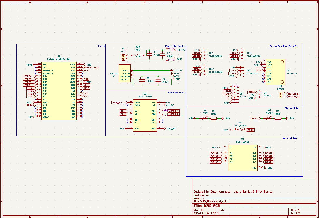
The ESP32 DevKit (`U1`) sits at the centre. Battery voltage (~11.1 V, 3S) comes in at the `VCC` screw terminal (`J1`) and splits two ways: the motor driver takes it directly, and a MINI560 buck (`V1`, bulk caps `C1`–`C4`) drops it to the 5 V logic rail. The RDB-14450 driver (`U2`) takes `PWM_MOTOR` / `AIN1` / `AIN2` from the ESP32 and drives `MOTOR_1/2` out to the screw terminal `J5`. The four HC-SR04s land on headers `US1`–`US4` (5 V / TRIG / ECHO / GND); their 5 V echo lines return through a BOB-12009 level shifter (`U3`) that steps `ECHO1`–`ECHO4` down to 3.3 V for the ESP32. The MPU-6050 (`U4`) is on I²C. The `TO_PI` header (`J3`) is the entire link to the Raspberry Pi — `RX` / `TX` for the V2 protocol, `READY` for the handshake, `PRGN` for the start button (`SW1`), plus 3.3 V / GND. Two status LEDs (`D1` PWR, `D2` READY) complete the operator interface from [§4.7](#47-startup-handshake).
**Populated board** ([`schemes/pcb_render.png`](schemes/pcb_render.png)):
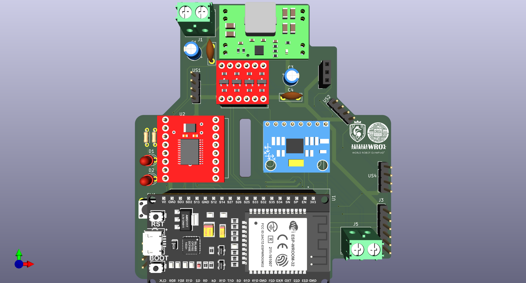
**Board outline** ([`electrical/PCB_dimensions.png`](electrical/PCB_dimensions.png)):
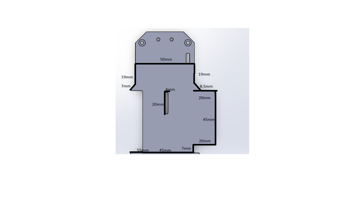
The board is a custom non-rectangular shape (~55 mm at its widest) that nests into the chassis around the Raspberry Pi 4 and the drivetrain — the electronics-first packaging from [§1.1](#11-design-goals) in physical form. The cut-outs and the mounting-hole row let the PCB, the steering and the sensor mounts share one footprint without stacking height.
#### v2 PCB — two-floor board (in design)
The v1 board is a single layer of components shaped around the Raspberry Pi 4. The v2 chassis is ≈7 cm shorter, the Pi moves to the top, and the robot gains four ToF sensors (each with its own XSHUT line), the BNO085 UART and a second regulator. All of that does not fit on one footprint, so the v2 board is designed as **two stacked floors** on standoffs:
| Floor | Contents | Why separate |
|---|---|---|
| **Power** (bottom) | Battery input (XT60), switch and fuse, two Mini560 regulators (Pi / everything else), motor driver | Keeps the switching regulators and motor currents, with their heat and noise, away from the signal lines. It is also the heaviest floor, so it sits low. |
| **Logic** (top) | ESP32, level shifter, headers for 3 HC-SR04, 4 VL53L1X (I²C + XSHUT), BNO085 (UART), servo, start button and LEDs, the link to the Pi | All signal connectors on one accessible floor |
Status: schematic and layout in progress in KiCad. The v1 project in [`electrical/WRO_RevA/`](electrical/WRO_RevA/) remains the reference until RevB is fabricated. The wiring diagram will be updated with it.
### 3.4 Main computer — Raspberry Pi 5 (v2)
**Why we upgraded.** We profiled the Pi 4 running the real race code. The main Python thread was using **97% of one core**, and the loop ran at **14–18 fps** depending on the scene. Most of that time was spent on vision, not on the camera: ~5 ms capture, 17–22 ms color detection, 45–48 ms bird's-eye view and centerline. With the remote desktop client running, the Pi 4 also reached **84 °C** and entered thermal throttling. A faster CPU attacks every stage at once.
**Measured result.** We ran the unmodified race runtime on the Pi 5, replaying a recorded Obstacle Challenge run as the camera input at 30 fps:
| | Raspberry Pi 4 | Raspberry Pi 5 (16 GB) |
|---|---|---|
| Vision loop rate | ~15.5 fps (same run, recorded live) | **40–41.5 fps**, stable for 60 s |
| Time per frame | ~65 ms | ~25 ms |
| Temperature | up to 84 °C, throttled | 46 → 52 °C, no throttling (`0x0`) |
The Pi 5 also has the official **Active Cooler**. Its fan is controlled by the firmware: it stays off below 50 °C and speeds up in steps up to 100% at 75 °C. The **M.2 HAT+** is installed for a future NVMe SSD, which will mainly make storage more durable when recording a video of every run.
**What the port required:**
- **Per-frame constants.** Many filters and confirmations in the runtime count *frames* and were tuned at ~14 fps. At 40 fps they would run almost 3× faster in real time. The loop also doesn't wait for a new camera frame. Before racing on the Pi 5 we either cap the loop at the old rate or rescale those constants.
- **Serial port.** On the Pi 5, `/dev/serial0` points to the debug UART connector, not to the GPIO header. The ESP32 link uses `/dev/ttyAMA0` (GPIO 14/15).
- **GPIO.** The original `RPi.GPIO` library does not support the Pi 5, so we use the drop-in `rpi-lgpio` package and the code stays the same.
- **Camera.** The Pi 5 uses the smaller 22-pin camera connector, so the Camera v2 needs a 22-to-15-pin cable. The automatic camera detection did not recognize our module, so `/boot/firmware/config.txt` loads it explicitly (`camera_auto_detect=0`, `dtoverlay=imx219,cam1`). The capture pipeline must request `format=BGRx`; without it, the camera source fails to negotiate a format on the Pi 5's image processor (`not-negotiated`). BGRx comes straight from the image processor at 30 fps using ~2% CPU.
- **Live view without a monitor.** The remote-desktop client used on the Pi 4 does not work on the Pi 5 desktop (Wayland). [`pure_pursuit/cam_web.py`](src/RASPI/cam/pure_pursuit/cam_web.py) streams the camera (or the race HUD with `--hud`) to a browser, with the color-calibration controls.
- **OpenCV.** It must be the system package (`python3-opencv`), because the pip wheel is built without the GStreamer backend that the `libcamerasrc` capture pipeline needs.
---
# 4. Software Architecture
### 4.1 System overview — two controllers, one link
Responsibility is split across two processors by hardware strength:
```
RASPBERRY PI 4 (Python, OpenCV) ESP32 (Arduino / C++)
┌───────────────────────────────────────────┐ V2 ┌────────────────────────────────────┐
│ Camera → BEV homography → floor centerline│ UART │ readPiSerial() → parse V2 │
│ Pillar detection (HSV) + corner-line track│ ──────► │ │
│ Rolling obstacle memory (dead reckoning) │ 115200 │ 6-state FSM │
│ Pure Pursuit geometric controller │ │ SIGUIENDO / GIRANDO / RECUPERANDO │
│ RECUPERANDO trigger (measured state) │ ◄────── │ CRUCERO / MANIOBRA / TERMINANDO │
│ builds one V2 line per processed frame │ ACK:V2 │ cascade PID (wall + gyro) │
└───────────────────────────────────────────┘ ang= │ servo + motor PWM, HC-SR04, MPU │
est= dir= └────────────────────────────────────┘
```
- The **Pi** decides *where to steer*: it turns the camera frame into a top-down view, extracts a drivable centerline, runs a Pure Pursuit controller against it, and reduces the result to a single normalized steering value plus a few status flags. It processes 1 of every 3 captured frames (~12–15 Hz effective).
- The **ESP32** decides *how to drive*: it owns the 50 Hz control loop, the finite state machine, corner detection, the recovery behaviour, and every actuator. In the Obstacle round it treats the Pi's steering value as the primary reference while Pure Pursuit is active, and falls back to its own wall + gyro PID if the Pi goes silent for more than 800 ms. In the Open round it ignores the Pi's steer altogether and runs on wall + gyro PID the whole time (§4.5).
Why not one processor? Real-time GPIO timing (ultrasonic pulses, servo/motor PWM, gyro sampling) and non-deterministic OpenCV latency don't coexist well on one core. Linux can't guarantee a µs-accurate pulse while an HSV pass is running; a microcontroller can't run OpenCV. Splitting them lets each run at its own natural rate, and a late UART packet just means the ESP32 reuses the last command instead of stalling. This trade-off is analyzed in [Section 5](#5-systemic-thinking--engineering-decisions).
**Where to start reading the code:** the Pi loop is [`pure_pursuit/runtime_nuevo.py`](src/RASPI/cam/pure_pursuit/runtime_nuevo.py) (`run()` → per-frame block); the ESP32 loop is [`PurePursuit.ino`](src/ESP32/PurePursuit/PurePursuit.ino) (`loop()` → the `switch (estado)`). Every module is annotated in [Section 8](#8-repository-structure); tunables live in [`pure_pursuit/config.py`](src/RASPI/cam/pure_pursuit/config.py).
### 4.2 Inter-controller protocol ("V2")
One line per processed frame, newline-terminated, 115200 baud. The rest of Section 4 refers to these fields by name.
**Pi → ESP32:**
```
V2,obs=+0.123,turn=0,state=pp,prio=1,mem=18,pp=1,pasado=0,intr=0
```
| Field | Meaning |
|---|---|
| `obs` | Normalized steering, `steer_deg / 60`, range −1…+1 (`+` = right). |
| `turn` | Legacy directional hint — always `0`; turn direction is resolved on the ESP32 side. |
| `state` | Human-readable label for the journal (e.g. `pp`, `avoid_red`). |
| `prio` | `1` = an obstacle is actively being avoided → **ESP32 must not start a corner turn**. |
| `mem` | Frames of obstacle memory still live → also blocks corner detection while `> 0`. |
| `pp` | `1` = Pure Pursuit steering is authoritative (suspend the wall PID). |
| `pasado` | One-frame pulse: the Pi confirms the car has *physically* cleared an obstacle → enter RECUPERANDO. |
| `intr` | Interior-pass flag (disabled by default). |
**ESP32 → Pi:**
```
ACK:V2,ang=12.34,est=S,dir=L,...debug...
```
| Field | Meaning |
|---|---|
| `ang` | Integrated IMU heading `anguloGyro` (degrees); resets to 0 at each turn. |
| `est` | FSM state — `S` SIGUIENDO, `G` GIRANDO **or** MANIOBRA, `R` RECUPERANDO, `C` CRUCERO. |
| `dir` | Track turn direction — `?` until the first turn, then `L` / `R`. |
### 4.3 Vision pipeline (Raspberry Pi — `pure_pursuit/`)
Entry point: `pure_pursuit/runtime_nuevo.py`. Per processed frame:
1. **Capture** — a threaded grabber pulls frames from the Pi camera through a libcamera/GStreamer pipeline at 640 × 480 BGR, dropping stale buffers so the loop always sees the newest frame.
2. **Bird's-eye view (`bev.py`)** — a homography (inverse-perspective mapping) warps the camera frame to a top-down 400 × 400 image at 2 mm/px. The homography comes from `bev_calib.npz`, generated once by `calibrate.py` from a **3 × 3 grid of 9 physical floor markers** (RANSAC fit). We use 9 points, not the minimum 4: a 4-point fit is exact and can't detect a mis-click or extrapolate safely beyond the marked area, while 9 points let the solver average out click noise across the full range the centerline actually uses (from just ahead of the car out to ~550 mm).
3. **Pillar detection (`vision.py`)** — HSV masks for red and green, then contour filtering by area, **solidity** (compact blob ≈ 0.7–0.9, painted line < 0.4) and **aspect ratio** (< 2.2) so the mat's coloured lines are not mistaken for pillars.
4. **Centerline (`centerline.py`)** — a floor-colour mask in the BEV, minus inflated "keep-out" disks around each obstacle. The keep-out is **asymmetric per the WRO rule**: a red pillar inflates further to its *left* (car passes on the right), a green pillar further to its *right*. Rows are sampled bottom-to-top; each row blends the free-gap center with the WRO pass-side using a weight that ramps up as the car nears the can (not a binary switch). A 1-D moving average plus a per-step Δx clamp keep the path within the servo's curvature limit.
5. **Pure Pursuit (`controller.py`)** — a geometric pure-pursuit controller in BEV pixel space. Look-ahead is **adaptive**: it shrinks from 100 px toward 78 px as the nearest can closes *longitudinally*, so the car keeps translating and arcs around the can instead of pivoting in place. Output is slew-limited to 6°/frame to kill frame-to-frame steering whip.
6. **Serialize** — the steering angle is normalized (`obs = steer_deg / 60`) and packed into one V2 line with the status flags (§4.2).
```mermaid
flowchart TB
A["Capture — threaded grabber
Pi camera 640×480 BGR, drops stale buffers"]
B["BEV homography (bev.py)
IPM warp to 400×400 top-down, 2 mm/px
from bev_calib.npz (9-point RANSAC)"]
C["Pillar detection (vision.py)
HSV red/green + area + solidity + aspect ratio"]
D["Centerline (centerline.py)
floor mask minus asymmetric keep-out disks
red inflates left, green inflates right
pass-side weight ramps with distance"]
E["Rolling obstacle memory (obstacle_memory.py)
ego-motion: assumed speed + real IMU heading from ACK
confidence decay, prune-on-pass"]
F{"Measured RECUPERANDO trigger
ARM / CLEAR / SKEW — see §4.4"}
G["Pure Pursuit (controller.py)
geometric, look-ahead 100 to 78 px adaptive
slew-limited 6°/frame"]
H["Serialize one V2 line
obs = steer_deg / 60, plus prio / mem / pp / pasado"]
A --> B
B --> C
B --> D
C --> E
E --> D
E --> F
D --> G
G --> H
F --> H
H --> Z(["UART to ESP32 @ 115200"])
```
#### How the Pure Pursuit controller works
Pure Pursuit is a path-tracking method: instead of reacting to an *error signal*, the controller looks a fixed distance ahead along the path — the **look-ahead** — picks the point on the centerline at that distance, and computes the single steering angle whose turning arc, starting from the car's current pose, passes exactly through that point. Every frame the target point moves forward along the centerline and the car "chases" it, so the trajectory is always a smooth arc onto the path rather than a hand-tuned reaction curve.
```
centerline (from BEV) look-ahead point picked at
·····•·····•·····•···•···• ← target distance ld along the path
╲
╲ arc the steering angle produces
┌───┐ ╲
│car│────────────• robot pose (rear axle = reference)
└───┘
└─ α = bearing to target, steer = atan2(2·L·sin α, ld)
```
Why it fits this problem:
- The vision pipeline already produces a **path** (the centerline), not a point to servo onto — Pure Pursuit consumes that path directly.
- The look-ahead is a single, physically meaningful tuning knob: **short = cut hard toward the path** (fast dodge), **long = ease onto it** (smooth cruise). That is exactly the behaviour the obstacle logic needs, so avoidance is folded into the *same* controller by shrinking the look-ahead near a can instead of adding a separate avoidance mode.
- It degrades gracefully: a noisy or short path just moves the target point a little; there is no integrator to wind up and no error term to spike.
```python
dx = target[0] - robot_x # lateral offset to the look-ahead point (BEV px)
dy = robot_y - target[1] # forward distance to it
ld = max(1.0, math.hypot(dx, dy)) # actual chord length
alpha = math.atan2(dx, dy) # bearing to the point
steer_rad = math.atan2(2.0 * C.WHEELBASE_PX * math.sin(alpha), ld) # pure-pursuit arc
steer_deg = math.degrees(steer_rad)
if bev_obstacles: # a can is in play
steer_deg *= self._distance_steer_gain(...) # ramp 0.30→1.0 as it closes
steer_deg = max(-C.MAX_STEER_DEG, min(C.MAX_STEER_DEG, steer_deg))
steer_deg = clamp(steer_deg, prev ± C.PP_STEER_SLEW_DEG) # 6°/frame slew limit
```
`adaptive_lookahead` shrinks the look-ahead from 100 px toward 78 px, and `_distance_steer_gain` ramps the steering scale from 0.30 up to 1.0, both as the nearest can closes. Both key off the **longitudinal** distance to the can (forward gap), not the Euclidean one: a can still off to the side but level with the car used to keep those values relaxed, and the car drove straight past the point where it should have started turning. The WRO pass-side bias (right of red, left of green) is *not* handled here — it is already baked into the centerline by `centerline.py`, so the controller only has to follow the path it is given.
If `bev_calib.npz` is missing, the runtime falls back to a simple reactive PID on the pillar's x-position in the raw frame (`RED_TARGET_PX` / `GREEN_TARGET_PX`) so the car is never left without a controller.
### 4.4 Obstacle handling (Obstacle Challenge)
**Rolling obstacle memory (`obstacle_memory.py`).** The BEV only contains what the camera sees *now*; as the car closes on a can, the can leaves the bottom of the frame, its keep-out disc vanishes, and the centerline snaps back to center — cutting the corner onto the can. The memory fixes this: seen cans are stored as `(x, y, colour, confidence)` in robot-relative BEV coordinates and, every frame, the ego-motion is applied to every remembered can — forward travel from an assumed speed, rotation from the **real IMU heading change** in the ESP32 acknowledgement:
```python
dheading = heading_deg - self._prev_heading # real Δ from the ACK, degrees
ds_px = (C.ROBOT_SPEED_MMS * dt_s) / C.MM_PER_PX # assumed forward advance, BEV px
# a hard dodge rotates the car without translating it — shrink ds_px when |dheading| is large
ds_px *= turn_brake(dheading)
self._advance(ds_px, dheading) # each can: y += ds_px, then rotate −dheading about the robot
```
Fresh detections are merged in, unseen cans decay in confidence and are pruned once genuinely passed. The inflated keep-out therefore persists until the car has physically cleared the can. The `heading_deg` this relies on is exactly the value the ESP32 integrates for its own control (see §4.6) and echoes back — one shared heading, so the map rotates by the same angle the car actually turned.
**"Mine" vs "beyond the corner" (`corner_lines.py`).** The mat's orange corner lines are tracked row-by-row in the BEV. Each remembered can is classified as *mine* (on my straight, must be avoided) or *beyond* (on the next straight, ignore for now), with asymmetric hysteresis — quick to start avoiding, slow to stop — because starting to dodge is the safe side of a wrong call.
**Far hint (`far_hint.py`).** A PD controller on a pillar's offset in the *raw* camera frame (before it projects into the BEV range) nudges the steering to pre-center on a distant can, capped at ±12° so it can only hint, never dodge.
**Mid-turn detector (`mid_turn.py`).** While the ESP32 is turning, the rolling memory is disabled (its motion model assumes forward travel, which a pivot violates). This detector instead uses only the raw per-frame BEV projections and requires a same-colour can in a consistent position across several frames inside a close forward cone to "confirm" it. **Phase 1 (current): observe and log only** — it writes `[MTURN]` lines to the journal and does not yet change steering, so we can measure its reliability on-track before wiring it into the firmware.
#### Triggering RECUPERANDO from the obstacle memory
**The problem.** When the car has to swing wide around a can with no room to spare, it finishes the pass **crooked** — pointing 30–60° off the straight — and often with one wall out of ultrasonic range. At that exact moment the camera view is the least trustworthy (the centerline is short and skewed), so letting Pure Pursuit "straighten itself" from what it sees tends to over- or under-correct into a wall. The fix is to hand the wheel to the ESP32's wall + gyro PID (state `RECUPERANDO`) until the chassis is realigned — but *only* for a hard dodge. A gentle dodge with space to spare straightens itself fine and should not stop for a recovery.
**The trigger** (`_measured_recup_trigger` in [`runtime_nuevo.py`](src/RASPI/cam/pure_pursuit/runtime_nuevo.py)) does not dead-reckon the can itself — it reads the state the obstacle memory and the IMU already provide, and needs three things to line up:
```
1. ARM a real dodge is in progress:
the centerline's avoidance weight near the car's axis has been
≥ RECUP_MEAS_ARM_W for RECUP_MEAS_ARM_FRAMES straight frames.
On arming, snapshot heading_ref = current heading (the straight's heading).
2. CLEAR the memory no longer places any Red/Green can both far enough ahead
of the axis AND close enough to the side to be in the way
(going straight, the car's edge would clear it) — held for
RECUP_MEAS_CLEAR_FRAMES frames (or just 1 if a corner is imminent).
3. SKEW |heading − heading_ref| ≥ RECUP_MEAS_HEADING_DEG (25°)
→ there is actually something to straighten.
ARM && CLEAR && SKEW → emit pasado=1 (one-frame pulse) → ESP32 enters RECUPERANDO
CLEAR but never SKEW for RECUP_MEAS_GENTLE_FRAMES → disarm quietly, no RECUPERANDO
```
```mermaid
flowchart TB
S(["Each processed frame"]) --> ARM{"Centerline avoidance weight near the car axis
>= ARM_W for ARM_FRAMES consecutive frames?"}
ARM -- no --> S
ARM -- yes --> SNAP["Snapshot heading_ref = current heading
(the straight's heading)"]
SNAP --> CLR{"Memory places NO red/green can both far enough ahead
of the axis AND close enough to the side to be in the way?
held CLEAR_FRAMES frames (or 1 if a corner is imminent)"}
CLR -- no --> HOLD["Keep dodging (pasado = 0)"]
HOLD --> CLR
CLR -- yes --> SKEW{"abs(heading − heading_ref) >= 25° ?"}
SKEW -- "yes" --> FIRE["Emit pasado = 1 (one-frame pulse)
trigger disarms — fires once per dodge"]
SKEW -- "no, for GENTLE_FRAMES" --> DIS["Disarm quietly — the gentle dodge
straightens itself, no RECUPERANDO"]
FIRE --> ESP(["ESP32: SIGUIENDO → RECUPERANDO
wall + gyro PID realigns the chassis"])
```
Condition 3 is what separates the two cases: same "can is now behind me" geometry, but only the crooked one triggers a recovery. The trigger disarms on fire, so it emits **once per dodge** — a can that lingers in memory while the ESP32 straightens can't re-fire it. The can positions it checks are the same `(x, y)` the memory maintains — corrected by fresh detections while the can is visible, and carried by the *same* ego-motion the centerline uses once it isn't (see the memory snippet above) — so the trigger and the path always agree on where the can is.
This replaced an earlier approach that anchored the can's position when first seen and dead-reckoned it forward with an *assumed* speed and a bicycle model; that anchor drifted 200–400 mm within 1–2 s and fired either early (nose into the can) or far too late.
### 4.5 ESP32 finite state machine (`src/ESP32/PurePursuit/PurePursuit.ino`)
```
enum Estado { SIGUIENDO, RECUPERANDO, GIRANDO, CRUCERO, MANIOBRA, TERMINANDO, INICIO, ESTACIONANDO, ESTACIONANDO_PUNTA };
```
```mermaid
stateDiagram-v2
[*] --> WAIT_PI: setup() blocks on READY
WAIT_PI --> WAIT_FIRST_V2: READY acknowledged
WAIT_FIRST_V2 --> SIGUIENDO: first V2 line (motor gated at 0 until here)
SIGUIENDO --> RECUPERANDO: pasado=1, obstacle physically cleared [Obstacle]
SIGUIENDO --> GIRANDO: corner detected, cooldown elapsed [Open]
SIGUIENDO --> CRUCERO: straight clean, front sensor < FRONT_CRUCERO_CM [Obstacle]
RECUPERANDO --> SIGUIENDO: heading settled or timeout, lane clear
RECUPERANDO --> CRUCERO: heading settled or timeout, wall ahead [Obstacle]
GIRANDO --> SIGUIENDO: reaches AngGiro, turn counted, heading re-zeroed
GIRANDO --> TERMINANDO: 12th turn
CRUCERO --> SIGUIENDO: a new "mine" obstacle appears, not yet committed
CRUCERO --> MANIOBRA: front sensor at turn threshold (debounced), or CRUCERO timeout
MANIOBRA --> SIGUIENDO: sub-sequence done, turn counted, new straight from 0
MANIOBRA --> TERMINANDO: 12th turn
TERMINANDO --> [*]: drive like SIGUIENDO for TERMINANDO_MS, then stop
note right of MANIOBRA
Phase machine (a motor-coast precedes every reversal — H-bridge safety):
0 coast, 1 pivot (forward arc or reverse) to EXIT_DEG,
2 coast, 4 straight back-off, 5 coast, then finish.
Phase 3 = reverse stalled, coast, restart the pivot forward.
end note
```
*This is the complete state machine as it stands on branch `SectionTurning` — the current firmware. One flag, `const bool rondaObstaculos`, selects the profile. `false` (Open Challenge): only `SIGUIENDO` / `GIRANDO` / `RECUPERANDO` / `TERMINANDO` are reachable and corners are the continuous `GIRANDO` arc. `true` (Obstacle Challenge): `GIRANDO` is replaced by the segmented `CRUCERO` → `MANIOBRA` sequence and the `pasado`-driven `RECUPERANDO` is enabled. `RECUPERANDO` never aborts on a new obstacle — it straightens the chassis first, then hands back to `SIGUIENDO`, or to `CRUCERO` if the corner is already in reach. The `main` branch still carries an earlier 3-state cut (`SIGUIENDO` / `RECUPERANDO` / `GIRANDO`); the `SectionTurning` merge is tracked as iteration log v3.0. `WAIT_PI` / `WAIT_FIRST_V2` are the startup handshake (§4.7).*
| State | Role |
|---|---|
| **SIGUIENDO** | Normal driving. In the **Obstacle round**, steering = Pi's Pure Pursuit value, blended with a light gyro correction (weight 0.12) and, only on a clean straight, the wall PID (weight 0.30). In the **Open round** the Pi's steer is ignored entirely — steering is pure wall PID + gyro PID (see §4.5.1). Watches for the next corner and for obstacle flags from the Pi. |
| **GIRANDO** | Continuous corner (**Open round only**). Servo held at full lock, motor speed ramped down in steps as `\|anguloGyro\|` grows, exits at `\|anguloGyro\| ≥ AngGiro` — **76°** in the Open round (the continuous turn coasts the rest on inertia) vs. 90° for the Obstacle round. The first corner latches the track's turn direction from whichever wall opened up. 12 corners = 3 laps → `TERMINANDO`. |
| **RECUPERANDO** | *(Obstacle round)* Entered on the Pi's `pasado=1` pulse. Vision is handed off; wall PID + gyro PID (with widened limits) straighten the chassis back into the lane. Exits when the heading error settles (with a timeout safety net for corners where one wall legitimately reads "open"). |
| **CRUCERO** | *(Obstacle round)* Straight is clean and a corner is near (front sensor < 80 cm). The car drives straight on heading toward the wall: far away, vision keeps the centerline straight; once inside `CRUCERO_GYRO_CM`, control is pure gyro + wall PID. A new obstacle sends it back to SIGUIENDO. |
| **MANIOBRA** | *(Obstacle round)* Replaces the continuous turn. At 30–60 cm from the wall a one-time decision is latched: **turn direction** = the side whose wall is open; **forward arc vs. reverse pivot** = chosen from the distance to the *outer* wall of the turn (tight against it → reverse pivot; room to swing → forward arc). A multi-phase sub-machine runs it, with motor-**coast** phases inserted between every direction reversal (plugging the H-bridge under load destroyed a TB6612 during testing). An optional short straight back-off afterward buys room on the new straight. Then it straightens, zeroes the heading for the new straight, counts the turn and returns to SIGUIENDO. |
| **TERMINANDO** | Entered automatically after the 12th turn **instead of braking on the spot**. Drives exactly like SIGUIENDO (same controller, but corner detection disabled) for `TERMINANDO_MS` (~1 s, tunable) so the car rolls forward into the start area, then cuts the motor and ends the race. Keeps the finish inside the start section instead of wherever the last corner happened to end. |
The turn-direction is latched once (all corners of a WRO track turn the same way); the forward-vs-reverse choice is made fresh at every corner from the distance to the **outer** wall of the turn ([`decidirManiobra()`](src/ESP32/PurePursuit/PurePursuit.ino)):
```cpp
// outer wall = the one that is NOT the opening (right turn → left wall, and vice-versa)
long distExt = maniobraGirarDer ? distL : distR;
maniobraReversa = (distExt >= HUG_CM); // room to swing → reverse pivot
maniobraRetroceso = (distExt > MANIOBRA_BACKOFF_MIN_CM); // slack → short back-off after
```
**One flag switches the whole driving profile:** `const bool rondaObstaculos` at the top of `PurePursuit.ino`.
| | Open Challenge (`false`) | Obstacle Challenge (`true`) |
|---|---|---|
| Steering source | ESP32 wall PID + gyro PID **only** — the Pi's Pure Pursuit steer, `prio`/`mem`/`pasado` flags are all ignored | Pi Pure Pursuit centerline; PID as blend / fallback / RECUPERANDO |
| Corner turn | continuous `GIRANDO` | `CRUCERO` → `MANIOBRA` segmented |
| Turn target `AngGiro` | 76° (the continuous turn coasts the rest on inertia) | 90° |
| Motor PWM ceiling `MOTOR_MAX` | 180 — fast; the in-turn speed ramp does the slowing | 100 — slow, for fine maneuvers |
| `RECUPERANDO` / obstacle handling | never entered | active |
`TERMINANDO` and the cascade PID run in both.
#### 4.5.1 Open-round corner hardening
With the Pi's vision out of the loop, three guards keep the continuous turn honest:
- **`giroArmado` — corridor arm.** `detectarEsquina()` is not allowed to fire a turn until the car has first confirmed it is *inside* a corridor: both side walls < 100 cm for `PASILLO_FRAMES` (3) consecutive frames. A wide reading in the start zone therefore can't trigger a false first turn. Once armed it stays armed for the whole run, so real corners are never delayed by it (unlike a fixed time lockout).
- **Front-wall approach slow-down.** When the front sensor sees the end wall closer than `FRONT_SLOWDOWN_CM` (60 cm), speed drops to `VEL_APROX_CERRADA` (140) so `detectarEsquina()` gets a clean read of which side opens before the car is on top of the corner.
- **`marchaIniciada` timer re-anchor.** The start-guard timer (`timeStart`) is reset to the instant the car actually starts rolling — not to when `READY` arrived seconds earlier — so its window is measured from roll-off.
#### 4.5.2 States added for the national final: start from the lot and parking
The diagram above shows the six driving states. Three more were added between 2026-09-07 and the national final:
| State | Entered when | What it does |
|---|---|---|
| `INICIO` | The Pi sends `inicio=1` (the car starts inside the parking lot) | Scripted S-shaped exit from the lot, gyro-checked, then `SIGUIENDO` |
| `ESTACIONANDO` | Last corner, parking mode `PARK_PARALELO` | Parallel parking in reverse inside the magenta lot |
| `ESTACIONANDO_PUNTA` | Last corner, parking mode `PARK_PUNTA` | Simpler nose-in partial parking (fallback) |
- **Start in the lot.** While disarmed, the Pi measures the share of magenta in the frame. When the button is pressed it decides once whether the car is inside the parking lot, and sends `inicio=1` if so. The ESP32 then runs `INICIO`: it swings out of the lot, drives straight, counter-steers back to the track heading, and backs up briefly to square up before the first straight.
- **Parking.** After the last corner the car follows the outer wall. It detects the lot from the side ultrasonic profile (wall → gap → wall), and the camera confirms the magenta walls. Then it parks **in reverse** in `ESTACIONANDO`. During parking, the heading reference is re-measured against the wall to cancel the gyro drift collected over 3 laps (`PARK_TRIM_*`). Runs 1025, 1052 and 1064 produced perfect parallel parks, and we keep their constants as the reference set.
### 4.6 Cascade PID (always running underneath)
Even in Pure Pursuit mode the ESP32 computes its dual cascade PID every loop — it is the fallback, the RECUPERANDO/CRUCERO controller, and the blend term in SIGUIENDO.
```
┌────────────────────┐ heading ┌────────────────────┐
distL─distR ─►│ OUTER PID │─ setpoint ──►│ INNER PID │──► servo
│ (wall centering) │ │ (heading control) │
└────────────────────┘ └────────────────────┘
▲ ▲
HC-SR04 readings MPU-6050 heading
```
The single-loop `error = distL − distR` controller it replaced failed past ~30° of yaw: the HC-SR04's conical beam hits the wall obliquely, both sensors over-report, the difference sits near zero while the car drifts into a wall. The outer loop turns lateral wall error into a target heading; the inner loop drives the servo to that heading using the IMU, which doesn't care about beam geometry.
**Tuned gains:** `KpWall 1.0 / KiWall 0.0 / KdWall 1.2`, `KpGyro 2.0 / KiGyro 0.0 / KdGyro 0.5`. Both integral terms are **disabled on purpose** — integral built up on long straights and released as a large steering impulse at corner entry, overshooting into the opposite wall. The derivative terms give enough steady-state correction on their own. Raw ultrasonic reads pass through an EMA filter (`alpha = 0.85`) before the PID.
```cpp
// OUTER: lateral wall error → steering contribution (Ki = 0)
errorWall = constrain(distL - distR, -50, 50);
outputWall = KpWall*errorWall + KdWall*(errorWall - prevErrorWall)/dt;
// INNER: heading error vs. the straight's reference heading (Ki = 0)
errorGyro = anguloObjetivo - anguloGyro;
outputGyro = KpGyro*errorGyro + KdGyro*(errorGyro - prevErrorGyro)/dt;
// SIGUIENDO with Pure Pursuit active: the Pi's steer leads, PID only trims a clean straight
servo = centroServo - (steerDeg - outputGyro*PP_GYRO_BLEND - outputWall*PP_WALL_BLEND);
// fallback / RECUPERANDO / CRUCERO-near-wall: PID alone
// servo = centroServo + (outputWall + outputGyro);
```
Heading is integrated on the ESP32 from the gyro Z axis, with the 1°/s deadband that keeps MEMS thermal noise from drifting the straight-line heading:
```cpp
float gz = mpu.getGyroZ() / gyroScale;
if (abs(gz) < 1.0) gz = 0; // 1°/s deadband
anguloGyro += gz * dt; // this is the value echoed back to the Pi
```
### 4.7 Startup handshake
1. Pi lights the LED on **GPIO 27** — "Pi is up".
2. Pi waits for the start button on **GPIO 17**.
3. Camera warm-up (~40 frames discarded to settle exposure).
4. Pi sends `READY` ×3; the ESP32 has been blocking in `setup()` waiting for it.
5. ESP32 replies `ACK:READY`, then **holds the motor at zero until the first real V2 line arrives** (a gate so the car never rolls forward on the fallback PID before Pure Pursuit is actually streaming). On the first frame it then rolls, `marchaIniciada` re-anchors the start-guard timer to that instant.
6. Main loop runs until 12 turns are counted, then `TERMINANDO` drives ~1 s more into the start area and stops.
```mermaid
sequenceDiagram
participant Pi as Raspberry Pi
participant ESP as ESP32
Pi->>Pi: Light LED on GPIO 27 ("Pi is up")
Pi->>Pi: Wait for start button (GPIO 17)
Pi->>Pi: Camera warm-up (~40 frames discarded)
Note over ESP: setup() is blocking, waiting for READY
Pi->>ESP: READY x3
ESP->>Pi: ACK:READY
Note over ESP: Motor held at 0 until the first V2 line
Pi->>ESP: First V2 line (obs + flags)
Note over ESP: Car rolls — start-guard timer re-anchored to this instant
loop Every processed frame (~12-15 Hz)
Pi->>ESP: V2 line — obs, prio, mem, pp, pasado
ESP->>Pi: ACK:V2 — ang (heading), est (S/G/R), dir (?/L/R)
end
Note over ESP: 12 turns counted, then roll ~1 s into start zone and stop
```
### 4.8 Development status
| Module | Challenge | Status |
|---|---|---|
| BEV homography + 9-point calibration tool | both | Complete |
| Floor centerline extraction | both | Complete |
| Pure Pursuit geometric controller | both | Complete, track-tuned |
| ESP32 cascade PID + fallback | both | Complete |
| Continuous corner turn (GIRANDO) | Open | Complete, track-tuned |
| Open-round pure-PID mode + corner hardening (`giroArmado`, approach slow-down) | Open | Implemented, not track-tuned |
| Return-to-start finish (TERMINANDO) | both | Implemented, not track-tuned |
| Pillar detection (HSV + shape filter) | Obstacle | Complete |
| Asymmetric WRO keep-out in centerline | Obstacle | Complete |
| Rolling obstacle memory (dead reckoning) | Obstacle | Complete, track-tuned |
| Corner-line "mine / beyond" classifier | Obstacle | Complete |
| Measured-state RECUPERANDO trigger | Obstacle | Complete, track-tuned |
| Segmented turn (CRUCERO → MANIOBRA) | Obstacle | Raced at the national final; forward/reverse hysteresis added after it ([ERR-22](docs/engineering-log.md#err-22--the-corner-maneuver-changed-its-mind-at-the-last-moment)) |
| Mid-turn cone detector | Obstacle | Phase 1 — logging only |
| Start from the parking lot (`INICIO`) | Obstacle | Raced at the national final |
| Parallel parking (`ESTACIONANDO`) | Obstacle | Working in testing — perfect parks in runs 1025, 1052, 1064 |
| Floor-referenced color correction + ratio tests | both | Complete ([ERR-15](docs/engineering-log.md#err-15--in-a-darker-room-the-orange-line-was-read-as-red), [ERR-17](docs/engineering-log.md#err-17--strong-light-tape-read-as-red-pale-floor-read-as-green)) |
| Raspberry Pi 5 port | both | In progress — pipeline at 40 fps on recorded video; per-frame constants pending (§3.4) |
| VL53L1X ToF sensors | both | Bench testing (§3.2) |
---
# 5. Systemic Thinking & Engineering Decisions
### 5.0 Design constraints
Every decision in this section was made inside these limits:
| Constraint | Source | Limit | How it shaped the robot |
|---|---|---|---|
| Size | Rule 11.1 | ≤ 300 × 200 × 300 mm | We stay far below it on purpose (v2 ≈17 cm long) to have room to dodge and park ([§2.6](#26-v2-chassis--shorter-car-pi-on-top)) |
| Weight | Rule 11.2 | ≤ 1.5 kg | 564 g in v1; light enough that the N20 at 100:1 accelerates cleanly |
| Drive | Rule 11.3 | One driving axle and one steering actuator; no differential drive | Ackermann rack-and-pinion + a printed rear differential |
| No radio during rounds | Rule 11.10 | Wi-Fi, Bluetooth and Tailscale must be off | All debugging is offline: a recorded video and journal per run. The live view is used only in practice |
| No manual calibration at the start | Rule 9.9 | Nothing set by hand on the table | Gyro bias measured automatically at boot; camera and color calibration done in the practice time |
| Black walls | Field rules 13.3–13.4 | Dark, IR-absorbing walls | Ultrasonic + ToF cross-check ([§3.2](#why-both-ultrasonic-and-tof)) |
| Round time and ranking | Rules 9.1, 10.7–10.8 | 3 minutes; points first, time breaks ties | Points over time: stop-and-turn corners ([§4.5](#45-esp32-finite-state-machine-srcesp32purepursuitpurepursuitino)) |
| Processing | Raspberry Pi 4 | 14–18 fps, compute-bound (97% of one core) | Raspberry Pi 5: 40 fps on the same pipeline ([§3.4](#34-main-computer--raspberry-pi-5-v2)) |
| Heat | Enclosed Pi 4 | 84 °C → thermal throttling | Pi 5 + Active Cooler, mounted on top ([§2.6](#26-v2-chassis--shorter-car-pi-on-top)) |
| Power quality | Pi undervoltage | A 0.3 V drop throttled the CPU | 22 AWG wiring; a dedicated regulator for the Pi in v2 ([§3.1](#v2-power-budget)) |
| Battery voltage | Open-loop motor (v1) | Behavior changes with charge level | Race window of 11.70–12.15 V; v2 encoder motor mounted for closed-loop speed |
| Time | Calendar | ~11 weeks between the national (09-19) and international (12-08) finals; documentation due 11-24 | Every change must be checkable on recorded runs (replay) before it gets track time |
| Budget | Team | v1 ≈155 USD; the Raspberry Pi 5 alone is ≈410 USD | The Pi 5 is the big v2 expense; the sensors were picked from the low-cost, widely documented ones (VL53L1X, BNO085) |
### 5.1 Subsystem interaction map
```mermaid
flowchart LR
subgraph PI["Raspberry Pi 4 — vision and planning"]
CAM["Pi camera"] --> BEV["BEV homography"]
BEV --> PD["Pillar detection (HSV)"]
BEV --> CL["Centerline
asymmetric keep-out"]
PD --> OM["Rolling obstacle memory"]
OM --> CL
OM --> TRG["RECUPERANDO trigger"]
CL --> PP["Pure Pursuit"]
end
subgraph ESP["ESP32 — real-time control"]
OUT["OUTER PID
wall centering"] --> INN["INNER PID
heading via IMU"]
FSM["Finite state machine"]
SEG["CRUCERO / MANIOBRA
segmented turn"]
INN --> ACT(["servo + motor PWM"])
FSM --> ACT
SEG --> ACT
end
USLR["HC-SR04 left / right"] --> OUT
USF["HC-SR04 front"] --> SEG
IMU["MPU-6050"] --> INN
PP -- "obs (V2 @ 115200)" --> FSM
TRG -- "prio / mem / pasado" --> FSM
IMU -- "ACK: heading" --> OM
```
The IMU heading is the shared currency: the ESP32 integrates it for its own control *and* ships it back so the Pi's obstacle memory can rotate its map by the exact same angle. Everything the Pi decides reaches the ESP32 as four flags and one number; everything the ESP32 knows about its own state reaches the Pi as three fields. Neither side can stall the other.
### 5.2 Key engineering trade-offs
**Trade-off 1 — one processor vs. two.** One ESP32 would remove the UART protocol, the Linux boot time and the sync logic. But real-time computer vision breaks single-core timing: a 640 × 480 HSV pass is 8–15 ms on the Pi 4, and running it alongside µs-accurate GPIO pulses gives non-deterministic jitter. Splitting by hardware strength (Pi = vision + planning, ESP32 = timing + actuation) lets each run at its own rate; a delayed packet just means the ESP32 reuses the last command. The cost — a protocol to maintain and two codebases — was worth deterministic control.
**Trade-off 2 — VL53L0X ToF vs. HC-SR04 ultrasonic.** ToF wins on paper (±3 mm vs ±15 mm, narrow beam). But the WRO field's matte-black walls absorbed the 940 nm IR and returned out-of-range at 300 mm in our tests. Ultrasonic reflects off anything. We chose reliability and closed the accuracy gap with EMA filtering, a front-channel median filter, and the cascade PID.
**Trade-off 3 — reactive steering vs. geometric Pure Pursuit.** The first vision controller steered proportionally to the pillar's pixel offset. It over-reacted close in and under-reacted far out, and had no model of the car's path. Pure Pursuit against a BEV centerline gives a geometrically correct steering angle for a chosen look-ahead, and the look-ahead becomes a single tuning knob for "how hard to dodge". The cost is the BEV calibration step; the payoff is predictable arcs instead of hand-tuned reaction curves.
**Trade-off 4 — forgetting a can when it leaves the frame vs. a rolling memory.** The honest, stateless option is to only avoid what the camera sees now — but that cuts the corner onto a can the moment it drops out of view. The rolling memory keeps the keep-out alive using dead reckoning (assumed speed + real IMU rotation). The risk it adds — a "ghost" can from accumulated error — is bounded by confidence decay and a prune-on-pass rule, and is the safer failure (dodge a can that's already gone vs. clip one that's still there).
**Trade-off 5 — continuous turn vs. segmented stop-and-maneuver (Obstacle round).** A continuous 90° arc is fast and simple and works well in the Open round. In the Obstacle round, a can placed near the corner mouth turns that blind arc into a coin-flip. The `SectionTurning` design trades speed for certainty: cruise straight to a known distance from the wall (front sensor), stop, then run a deterministic maneuver — a forward arc if there's room, a reverse pivot if the car is tight against the outer wall. It is slower, but every corner becomes repeatable, which is the same principle that drove the 100:1 gear choice.
**Trade-off 6 — forward arc vs. reverse pivot inside MANIOBRA.** A forward arc needs clear space ahead to swing through; a reverse pivot needs the car close to the wall first. Rather than pick one, the firmware measures the distance to the outer wall of the turn and chooses per corner, with a reverse-timeout that bails out into a forward finish if the pivot stalls.
### 5.3 Iteration log
Structural changes and the tuning passes that revealed something — routine per-run parameter tuning in `config.py` between track sessions is not listed. Each row links to the commit that introduced the change. `Status`: **Shipped** (on `main`, track-validated) · **On branch** (implemented, still tuning) · **Superseded** (replaced by a later row) · **Reverted** (tried on track, backed out).
A dated, phase-by-phase account of the same history — including the pre-repo design and per-peripheral bring-up work — is in the [Engineering Journal](ENGINEERING_JOURNAL.md).
| Stage | Date | Change | Why it changed | Evidence | Status |
|---|---|---|---|---|---|
| Mechanical + PCB | 2026-04-13 → 04-24 | Chassis, rack-and-pinion steering, printed differential and power PCB, designed from scratch | New vehicle every season | `283078e` … `51ea239` | Shipped |
| First firmware | 2026-05-09 | Single-loop PID on `distL − distR`, VL53L0X ToF ×2, 3-state FSM (`Controller_PI.ino`) | First open-round lap | `61544cb` | Superseded |
| v1.1 — ToF → ultrasonic | 2026-05 | Both VL53L0X replaced with HC-SR04 | ToF lost the black wall past ~70 cm — [ERR-01](#err-01--vl53l0x-lost-the-black-wall-past-70-cm) | `61544cb` era | Shipped |
| v1.2 — remove the integrators | 2026-05 → 06 | `Ki = 0` on both PID loops | Integral wound up on the straights and released as one impulse at corner entry → overshoot into the far wall | `Controller_PI.ino` history | Shipped |
| v1.3 — cascade PID | 2026-05 → 06 | Outer loop (wall error → target heading) + inner loop (heading → servo, via IMU) | The `distL − distR` error goes blind past ~30° of yaw — [ERR-02](#err-02--wall-error-goes-blind-at-high-yaw) | `Controller_PI.ino` history | Shipped |
| Camera integration | 2026-05-23 | Pi camera, track-edge detection, BEV calibration tool (`calibrate.py`) | Lane geometry the ultrasonics can't see | `21fe8df`, `5797487` | Superseded |
| Two-controller split + deploy infra | 2026-06-08 → 06-09 | Pi ↔ ESP32 over UART; `wro-runtime.service`, VNC, push-to-deploy CI | OpenCV latency and µs GPIO timing can't share one core ([§5.2](#52-key-engineering-trade-offs)) | `69f82a9`, `a065d78` | Shipped |
| v2.0 — Pure Pursuit + centerline | 2026-06-13 → 06-22 | BEV homography → floor centerline → geometric Pure Pursuit (`pure_pursuit/`) | Reactive pillar-offset PID had no path model — over-reacted near, under-reacted far | `95f3744`, `e494d8c`, `556266b` | Shipped |
| Camera lens FOV 63° → 120° | 2026-07 → 08-07 | Wide-angle NoIR lens (swapped over the July break); on return, pinned white-balance (`awb-enable=false colour-gains=<1.2,1.5>`) and re-tuned the obstacle RGB ranges | Needed more forward range for the obstacle round; the wide lens has no IR-cut filter, so the raw image had a heavy red cast — [ERR-03](#err-03--wide-angle-noir-lens-put-a-red-cast-on-every-frame) | `945c2f1` | Shipped |
| v2.1 — offline sim | 2026-08-11 | Kinematic bicycle sim (`pure_pursuit_sim.py`, 520 lines) + `runtime_nuevo.py` | Tune controller logic without track time | `0a2c5d2` | Shipped |
| v2.2 — BEV calibration 4 → 9 points | 2026-08-13 | RANSAC fit over a 3×3 marker grid | A 4-point fit is exact — no way to reject a mis-click or check reprojection error | `daf1e03` | Shipped |
| v2.3 — corner-line detection | 2026-08-17 → 08-19 | Orange / blue ground-line tracking in the BEV | Turn trigger + a "my straight vs. the next one" boundary for obstacles | `d3a611e`, `8edc1b8` | Shipped |
| v2.4 — wall-aware steering (`ParedCenterline`) | 2026-08-20 → 08-21 | Centerline biased by ultrasonic wall distance; V2 protocol fixes | Centerline alone drifted toward the outer wall on wide corners | merges `f5066e1`, `24b2ec7` | Shipped |
| Open round validated | 2026-08-28 | — | 10 complete autonomous runs from varied start positions and field configs → focus moved to the Obstacle Challenge | [§6.2](#62-results-to-date) | Shipped |
| v2.5 — rolling obstacle memory | 2026-08-24 → 08-27 | Seen cans kept in a robot-relative map, advanced by assumed speed + **real IMU heading** from the ACK | Can leaves the frame → keep-out vanishes → centerline cuts the corner onto it | `a41ac0e`, `3c96abf`, `57d3218` | Shipped |
| v2.6 — hot start + run recording | 2026-08-28 | Pipeline runs disarmed during the button delay; ESP32 gated on the first V2 line; MJPG `.avi` HUD capture from button-press | Cold camera/serial cost ~2 s at the start; every run now leaves a reviewable artifact | `3245c1c`, `2355caf`, `f257371` | Shipped |
| v2.7 — undervoltage fix → frame-rate rescale | 2026-08-28 | Re-fed the Pi through 22 AWG leads (was dropping 0.3 V PCB→Pi → brown-outs, garbled frames); loop went ~7 → ~14 Hz; re-scaled every per-frame knob (slew, recovery frames, look-ahead floor) | Half the tunables were calibrated at 7 Hz and were now firing twice as fast — [ERR-08](#err-08--raspberry-pi-undervoltage-from-undersized-power-wiring) | `e4ca4f9`, `1a19cdb` | Shipped |
| v2.8 — pivot-trap root cause | 2026-08-28 → 08-29 | `LOOKAHEAD_MIN_PX` 60 → 78 (60 saturated the PP geometry); adaptive look-ahead + steer-gain re-keyed on the **longitudinal** gap; `forget_color_obstacles()` on pass so the centerline un-bends | Near a can the steer term hit ±0.9 (≈ full lock) → the car pivoted in place instead of arcing; `y` never advanced, RECUPERANDO never armed — [ERR-06](#err-06--the-car-pivoted-in-place-instead-of-arcing) | `1daf563` | Shipped |
| v2.9 — RECUPERANDO: anchor → measured state | 2026-08-28 → 08-29 | Retired the geometric dead-reckoning anchor; the trigger now reads the centerline avoidance weight, a heading snapshot, and the memory's own "is a can still in the way" test (`ARM` / `CLEAR` / `SKEW`) | The anchor integrated an *assumed* linear speed and drifted 200–400 mm in 1–2 s whenever the car had to turn hard — [ERR-07](#err-07--recuperando-trigger-tied-to-assumed-linear-speed) | `f24c547` → `25d0565` → **`52549c8`** | Shipped |
| v2.10 — turn-direction from the orange line | 2026-08-31 | Direction latched from the orange corner-line slope **during the run**, not pre-set | A pre-set direction is one more thing to get wrong at check-in | `a72a751`, `e641817` | Shipped |
| v2.11 — exterior cone at the corner mouth | 2026-08-31 | A can right at the corner: drive straight past it, *then* turn | The blind turn arc would sweep into it | `4e5ca40` | Shipped |
| v2.12 — camera-safe service restart | 2026-08-31 | CI + ops use `stop → sleep 4 → start`, never `systemctl restart` | `restart` doesn't release the CSI device — camera wedges, LED stays dark | `9aff6c9` | Shipped |
| v3.0 — segmented turns (`SectionTurning`) | 2026-09-01 | Obstacle round only: `GIRANDO` → `CRUCERO` (cruise to a set distance on the front sensor) → `MANIOBRA` (forward arc **or** reverse pivot from outer-wall distance); motor-coast phase before every direction reversal | A can at the corner mouth makes a blind 90° arc a coin-flip; a missing coast delay had already killed a driver + a motor — [ERR-04](#err-04--tb6612-and-motor-destroyed-by-a-reversal-with-no-coast-delay) | `9219f17` (+386 lines to `.ino`) | On branch |
| v3.1 — mid-turn cone detector | 2026-08-31 | `mid_turn.py` — raw per-frame BEV projections (rolling memory is off during a pivot); **Phase 1: log only** | A can first seen *during* the turn ends up beside the car afterwards → clipped | `6b0b5c7` | On branch (logging) |
| v3.2 — Open round runs pure PID | 2026-09-03 → 09-04 | Open round ignores the Pi steer — wall + gyro PID only; per-round `AngGiro` / `MOTOR_MAX`; `giroArmado` corridor-arm; front-wall approach slow-down; `TERMINANDO` finish | Open round doesn't need vision and was inheriting obstacle-round speed caps; a wide start-zone reading latched a false first turn — [ERR-05](#err-05--ultrasonic-beam-cone-bounces-off-the-corner) | `626fc91`, `13e05c1` | On branch |
| v3.3 — gyro heading-hold by default | 2026-09-05 | On a clean straight the gyro steers; vision steers only while a pillar of ours is present. `RECUPERANDO` made non-interruptible; proportional wall override (`wallPanic`) | Small dodges left the chassis 20–30° crooked and the car drifted into a wall (runs 679–690); run 700 = first clean 12-corner run | `9c4b75e` era | Shipped |
| v3.4 — start from the parking lot (`INICIO`) | 2026-09-09 | Pi measures the magenta share at the button press and sends `inicio=1`; ESP32 drives a scripted S-exit | The Obstacle Challenge may start inside the lot | `6a713e3` | Shipped |
| v3.5 — floor-referenced color correction | 2026-09-12 | Per-frame gains so the white mat matches a reference color | A darker room pushed the orange tape into the red range — [ERR-15](docs/engineering-log.md#err-15--in-a-darker-room-the-orange-line-was-read-as-red) | `7bd353f` | Shipped |
| v3.6 — camera check before arming | 2026-09-14 | Start blocked (LED off) until the camera delivers real frames | Run 860 drove 19 s with a blind camera — [ERR-12](docs/engineering-log.md#err-12--camera-blackout-mid-run) | `486cc4c` | Shipped |
| v3.7 — obstacle-memory merge guard | 2026-09-15 | A remembered pillar can't "reappear" where it physically couldn't be | Two reds across a corner merged into one (run 954) — [ERR-21](docs/engineering-log.md#err-21--two-red-signs-on-both-sides-of-a-corner-merged-into-one) | `8bfe4d0` | Shipped |
| v3.8 — red range for the new venue + B/R test | 2026-09-16 | Red hue 168–179 plus a blue/red ratio test against the pink walls | New venue: red pillars not detected at all (run 1013) — [ERR-14](docs/engineering-log.md#err-14--at-a-new-venue-red-signs-were-not-detected-at-all) | `e3784a8` | Shipped |
| v3.9 — parallel parking | 2026-09-12 → 09-17 | Lot found from the side-ultrasonic profile, reverse parallel park, heading trimmed against the wall | 15-point parking; perfect parks in runs 1025, 1052, 1064 | `cf28a0f`, `8ef47d0` | Shipped |
| **Release `v1.0-nacional`** | 2026-09-19 | Code raced at the national final — **1st place** | — | `d5cc66d` | Released |
| v3.10 — ratio tests + corner hysteresis | 2026-09-22 | `RED_GR_MAX`, `GREEN_S_MIN_MED`; forward/reverse decision with ±6 cm hysteresis | Strong light: tape read as red, floor as green (run 1190) — [ERR-17](docs/engineering-log.md#err-17--strong-light-tape-read-as-red-pale-floor-read-as-green); maneuver flip at the boundary (run 1188) — [ERR-22](docs/engineering-log.md#err-22--the-corner-maneuver-changed-its-mind-at-the-last-moment) | `96145ba` | Shipped |
| v4.0 — steering Ackermann fix + 19-tooth pinion | 2026-10-06 | Rack joints 43 → 47 mm, tie rods 18.13 mm, pinion 14 → 19 teeth | Anti-Ackermann (39.5° / 42.8°) and only ~37° of steering — [§2.4](#24-steering--rack-and-pinion-with-ackermann-geometry) | `844195e` | Validated in CAD |
| v4.1 — Raspberry Pi 5 + camera calibration | 2026-10-06 → 10-07 | Pi 5 16 GB + Active Cooler; `format=BGRx` capture; lens-shading table for our lens | Pi 4 compute-bound at 14–18 fps and throttling at 84 °C; magenta ring on the Pi 5 — [§3.4](#34-main-computer--raspberry-pi-5-v2) | `844195e` | On branch |
| v4.2 — VL53L1X ToF ×4 | 2026-10 | Front, left, right, rear on one I²C bus with XSHUT re-addressing | Front ultrasonic phantom echoes — [ERR-19](docs/engineering-log.md#err-19--phantom-echoes-from-the-front-ultrasonic) | `844195e` (test sketches) | Bench test |
### 5.4 Risk analysis
| Risk | Likelihood | Impact | Mitigation |
|---|---|---|---|
| HC-SR04 spike reading | Medium | Medium — brief PID disturbance | EMA on all channels; 5-sample median on the front channel; cascade inner loop dampens |
| Gyro drift over 3 laps | Low | Medium — heading offset grows | 1°/s deadband; heading zeroed after every turn; startup bias calibration |
| Camera mount shifts after BEV calibration | Low | High — warped top-view, wrong centerline | Rigid printed camera frame; recalibrate if the mount is touched; reprojection-error check in `calibrate.py` |
| Can leaves FOV mid-dodge → ghost obstacle | Medium | Medium — phantom keep-out | Confidence decay; prune-on-pass; memory disabled during turns |
| UART packet delayed by OpenCV load | Medium | Low — one stale command | ESP32 reuses last command; 800 ms timeout → autonomous wall+gyro fallback |
| Corner missed / mis-counted | Low | High — wrong lap count or direction | Conservative thresholds; 2 s cool-down; `prio`/`mem` block detection while dodging; front-sensor debounce in the Obstacle round |
| False first turn from a wide start-zone reading (Open round) | Medium | High — wrong direction latched for the whole run | `giroArmado`: corner detection stays disabled until both walls read < 100 cm for 3 frames; timers re-anchored to roll-off |
| MANIOBRA runs the car into the outer wall | Medium | High — DQ | Forward/reverse chosen from measured outer-wall distance; reverse-timeout fallback; optional post-maneuver back-off |
| H-bridge damage from direction reversal under load | Low (mitigated) | High — dead driver | Motor-coast phase inserted before every direction change (learned the hard way) |
| Servo driven into its end stop | Low | Low | Firmware clamps servo command to 20°–150° |
### 5.5 Failure & Incident log
Post-mortems for the failures that changed the design — what happened, the confirmed or suspected root cause, and what shipped in response. Several of these are the "learned the hard way" behind a row of the risk table in [§5.4](#54-risk-analysis).
#### ERR-01 — VL53L0X lost the black wall past 70 cm
| | |
|---|---|
| **First seen** | 2026-05, first wall-following bring-up |
| **Setup** | Two VL53L0X, one per side — the same left/right wall-distance job the HC-SR04s do now. |
| **Symptom** | Against the matte-black outer wall the effective range collapsed: past ~70 cm the sensor stopped returning correct distances. White walls read to spec. |
| **Impact** | No usable lateral reference on the black-walled portions of the track — roughly half the perimeter. |
| **Root cause** | The 940 nm IR is absorbed by the matte-black surface; too little returns for a time-of-flight solve. A single sensor on the bench reproduced it, so not a wiring or I²C fault. |
| **Fix** | Switched both channels to HC-SR04 ultrasonic (`61544cb` era) — sound reflects off any surface regardless of colour. Traded ±3 mm for ±15 mm and closed the gap in software (EMA on all channels, a 5-sample median on the front channel, the cascade PID). |
| **Status** | Resolved. Trade-off in [§5.2](#52-key-engineering-trade-offs). |
#### ERR-02 — wall error goes blind at high yaw
| | |
|---|---|
| **First seen** | 2026-05 — one of the earliest problems, open-round bring-up |
| **Symptom** | On corner entry and recovery the car kept drifting into a wall even though the PID output stayed small and stable. |
| **Root cause** | The HC-SR04's ~15° beam cone hits the wall obliquely once the chassis is yawed; both sensors over-report by similar amounts, so `distL − distR` sits near zero while the car is visibly crabbing toward one wall. This is inherent to the sensor geometry and is **still true today**. |
| **Fix** | The cascade PID stops the car *acting* on the blind error: the **outer** loop turns lateral wall error into a target heading, the **inner** loop drives the servo to that heading from the **IMU** ([§4.6](#46-cascade-pid-always-running-underneath)). At high yaw the wall term is unreliable but the inner loop is still steering on a good heading signal, so the car tracks true and re-centres once the walls read cleanly again. |
| **Status** | Mitigated by design — the sensor limitation remains; the IMU inner loop is what keeps it from mattering. This cascade is also the fallback / RECUPERANDO / CRUCERO law and the blend term in SIGUIENDO. |
#### ERR-03 — wide-angle NoIR lens put a red cast on every frame
| | |
|---|---|
| **First seen** | 2026-07, after the lens swap; corrected on return, 2026-08-07 |
| **Change that caused it** | Moved from a ~63° lens to a ~120° wide-angle lens to see far enough ahead to react to a pillar and read the corner on the same frame. The wide lens has no IR-cut filter (NoIR). |
| **Symptom** | Every frame came out heavily red-tinted. HSV masks for the floor, the orange line and the red/green pillars all broke. |
| **Root cause** | With no IR-cut filter the sensor integrates near-IR the eye doesn't see; on this sensor it lands mostly in the red channel. |
| **Fix** | Pinned the libcamera pipeline to fixed white-balance — `libcamerasrc awb-enable=false colour-gains=<1.2,1.5>` — so auto-WB can't chase the cast, then re-tuned the red/green HSV ranges on the corrected image (`945c2f1`, 2026-08-07, and the `vision.py` range passes after it). |
| **Status** | Resolved on the Pi 4. The wide FOV is now a net win — more track and obstacle zone per frame. |
| **v2 update (Raspberry Pi 5)** | The Pi 5 has a different image processor and tuning. With fixed gains only, the frame edges showed a strong **magenta ring** (corners R/G ≈ 1.31–1.40 on a white sheet). Root cause: the factory lens-shading table (ALSC) is made for the stock lens and *raises* red at the corners. Fix: new ALSC table calibrated for our lens from 5 photos of a white sheet with the official tool (`rpi-ctt`), brightness part symmetrized, shipped as [`camera_tuning/imx219_noir_wro_pi5.json`](src/RASPI/cam/camera_tuning/README.md) + gains `<1.10,1.51>`. Result: R/G and B/G = 1.00 at the center and at all corners. See [ERR-29](docs/engineering-log.md#err-29--raspberry-pi-5-magenta-ring-at-the-frame-edges). |
#### ERR-04 — TB6612 and motor destroyed by a reversal with no coast delay
| | |
|---|---|
| **First seen** | 2026-08 → 09, `SectionTurning` MANIOBRA bring-up |
| **Symptom** | While testing the maneuver, the code switched the motor from forward to reverse with no gap between the two. A current spike followed; **one TB6612 driver and one N20 motor were lost.** |
| **Root cause** | Software, not hardware: the forward → reverse transition energised the H-bridge in the opposite direction while the motor was still spinning. Back-EMF plus shoot-through current during the flip exceeded the driver's rating (classic "plugging"). |
| **Fix** | Every direction change in the firmware — forward↔reverse, in MANIOBRA and everywhere else — now passes through a mandatory motor-coast phase (`A1 = A2 = LOW`, `MANIOBRA_FRENO_MS = 300`) so the motor spins down before the opposite direction is energised (`9219f17`). |
| **Status** | Resolved. No recurrence since the coast phase went in. Risk table: "H-bridge damage from direction reversal under load". |
#### ERR-05 — ultrasonic beam cone bounces off the corner
| | |
|---|---|
| **First seen** | 2026-08, open-round corner tuning |
| **Symptom** | The car would sail past a corner opening — it "thought" it had not reached the end wall yet when it had actually passed the turn point some time earlier. |
| **Root cause** | The front HC-SR04's beam cone widens with distance; far from the end wall it catches the *corner* geometry and returns a longer bounce path, so the front distance reads larger than the true straight-ahead gap. Corner detection kept waiting. |
| **Fix** | The car slows to `VEL_APROX_CERRADA` once the front sensor drops below `FRONT_SLOWDOWN_CM` (60 cm) — more time to read *which* side opens before it is on top of the corner. Plus EMA + a 5-sample front-channel median to reject spikes, and a multi-frame confirmation before a turn is accepted. In the Obstacle round the same read drives `CRUCERO → MANIOBRA` instead of a continuous arc. |
| **Verification** | 10 complete open-round runs from varied start positions and field configurations after these changes. |
| **Status** | Resolved. |
#### ERR-06 — the car pivoted in place instead of arcing
| | |
|---|---|
| **First seen** | 2026-08-28, sessions ~orillas 414–416, right after the frame-rate doubled ([ERR-08](#err-08--raspberry-pi-undervoltage-from-undersized-power-wiring)) |
| **Symptom** | Approaching a can, the car rotated on the spot instead of driving a curve around it. The can's `y` in the BEV barely moved (≈ 40 mm/s) — turning, not translating. RECUPERANDO then never fired (the memory never saw the can go behind the axis) so the car dug deeper in. |
| **Root cause** | (1) the obstacle steer term jumped to ±0.9 — near full lock — which pivots this chassis at cruise PWM; (2) `LOOKAHEAD_MIN_PX = 60` saturated the Pure Pursuit geometry, and the adaptive look-ahead / steer-gain keyed on **Euclidean** distance, so a can level with the car but off to the side kept those relaxed and the car drove past the point it should have turned. |
| **Fix** | `LOOKAHEAD_MIN_PX` 60 → 78; adaptive look-ahead (100 → 78 px) and `_distance_steer_gain` (0.30 → 1.0) re-keyed on the **longitudinal** gap; on a confirmed pass the runtime calls `memory.forget_color_obstacles()` so the centerline un-bends and the car eases out (`1daf563`). |
| **Verification** | Session orillas 417: dodge steer ±0.4–0.7, the can's `y` advanced through the pass = arc not pivot, both cans cleared, all 12 turns completed. |
| **Status** | Resolved. |
#### ERR-07 — RECUPERANDO trigger tied to assumed linear speed
| | |
|---|---|
| **First seen** | 2026-08-28, on-track (`f24c547` geom v1, `25d0565` geom v2) |
| **Symptom** | The recover-into-lane state fired either too early — nosing into the can it was meant to have cleared — or seconds too late, after the car had already straightened badly. Worst whenever the pass needed a large heading change. |
| **Root cause** | The trigger anchored the can's position when first seen and dead-reckoned it forward using an **assumed linear speed** through a bicycle model. With no measurement feedback the anchor drifted 200–400 mm in 1–2 s, and a hard dodge — car rotating, barely translating — broke the speed assumption entirely. `SPEED_SCALE` at 1.0 / 0.35 / 0.60 were all wrong somewhere. |
| **Fix** | Retired the anchor (`52549c8`). `_measured_recup_trigger` reads state that is already measured: **ARM** when the centerline's avoidance weight near the axis has been high for several frames (snapshot the heading), **CLEAR** when the rolling memory places no can in the path, fire only if **SKEW** — `|heading − snapshot| ≥ 25°`. A gentle dodge that straightens itself never stops for a recovery. |
| **Status** | Resolved. Finding a dodge shape that armed RECUPERANDO *reliably* was the single longest debugging effort of the obstacle round. Full history in [§4.4](#44-obstacle-handling-obstacle-challenge). |
#### ERR-08 — Raspberry Pi undervoltage from undersized power wiring
| | |
|---|---|
| **First seen** | 2026-08 |
| **Symptom** | Frames processed poorly or not at all; the Pi would sometimes power off mid-run. Intermittent, load-dependent. |
| **Root cause** | ~0.3 V drop between the PCB 5 V rail and the Pi's input on undersized power leads. Under vision + steering load the Pi input sagged below its undervoltage threshold and it throttled or browned out. |
| **Fix** | Re-ran the Pi feed in 22 AWG. The rail held; the processing loop went from ~7 fps to ~14 fps. |
| **Follow-on** | The frame-rate jump then destabilised the evasion tuning — several knobs were expressed per-frame, and doubling the rate doubled their effect. Every per-frame parameter was re-scaled (iteration log v2.7); the pivot-trap ([ERR-06](#err-06--the-car-pivoted-in-place-instead-of-arcing)) surfaced in the same window. |
| **Status** | Resolved (wiring). Pi input voltage is now on the pre-run checklist. |
#### ERR-09 — separating "my straight" from "the next straight" *(open)*
| | |
|---|---|
| **First seen** | 2026-09, `SectionTurning` |
| **Symptom** | A can on the *next* straight, visible over the corner, is sometimes treated as an obstacle on the current straight (or vice-versa). Wrong classification → an unnecessary dodge, or a real can ignored. |
| **Current handling** | `corner_lines.py` tracks the orange corner line row-by-row in the BEV and labels each remembered can *mine* / *beyond* with asymmetric hysteresis (quick to start avoiding, slow to stop). Tried and reverted: locking onto the primary can by camera-bbox height (`601ea8d` … `ad4f71e`, 2026-09-02 — bbox too noisy frame to frame). |
| **Impact** | The main reason the obstacle round is not yet complete on every field configuration. Simple layouts pass reliably; a can straddling the corner sightline does not. |
| **Status** | **Open — active work.** |
#### ERR-10 onward — after 2026-09-06
The incidents after this point are logged in the same format, with run numbers and commits, in [`docs/engineering-log.md`](docs/engineering-log.md):
| ID | Incident | Status |
|---|---|---|
| [ERR-10](docs/engineering-log.md#err-10--power-cut-right-after-git-pull-left-files-empty) | Power cut right after `git pull` left files empty | Mitigated (procedure) |
| [ERR-11](docs/engineering-log.md#err-11--a-fresh-battery-over-rotates-the-dodges) | A fresh battery over-rotates the dodges | Mitigated (battery window) |
| [ERR-12](docs/engineering-log.md#err-12--camera-blackout-mid-run) | Camera blackout mid-run | Mitigated |
| [ERR-13](docs/engineering-log.md#err-13--pink-parking-lot-wall-detected-as-a-red-sign) | Pink parking-lot wall detected as a red pillar | Validated |
| [ERR-14](docs/engineering-log.md#err-14--at-a-new-venue-red-signs-were-not-detected-at-all) | New venue: red pillars not detected | Validated |
| [ERR-15](docs/engineering-log.md#err-15--in-a-darker-room-the-orange-line-was-read-as-red) | Darker room: orange line read as red | Validated |
| [ERR-16](docs/engineering-log.md#err-16--false-orange-line-in-the-middle-of-a-straight) | False orange line mid-straight | Validated |
| [ERR-17](docs/engineering-log.md#err-17--strong-light-tape-read-as-red-pale-floor-read-as-green) | Strong light: tape as red, floor as green | Validated (replay) |
| [ERR-18](docs/engineering-log.md#err-18--camera-tilted-up-caused-over-steering) | Camera tilted up → over-steering | Validated |
| [ERR-19](docs/engineering-log.md#err-19--phantom-echoes-from-the-front-ultrasonic) | Phantom echoes from the front ultrasonic | Under investigation |
| [ERR-20](docs/engineering-log.md#err-20--drift-towards-a-wall-after-small-dodges) | Drift towards a wall after small dodges | Validated |
| [ERR-21](docs/engineering-log.md#err-21--two-red-signs-on-both-sides-of-a-corner-merged-into-one) | Two reds across a corner merged into one | Validated (replay) |
| [ERR-22](docs/engineering-log.md#err-22--the-corner-maneuver-changed-its-mind-at-the-last-moment) | Corner maneuver changed its mind at the last moment | In repository |
| [ERR-23](docs/engineering-log.md#err-23--systematic-heading-offset-after-every-corner) | Systematic heading offset after every corner | Mitigated |
| [ERR-24](docs/engineering-log.md#err-24--green-then-red-slalom-the-red-is-grazed-sometimes) | Green-then-red slalom: red grazed "sometimes" | Under investigation |
| [ERR-25](docs/engineering-log.md#err-25--the-geometric-sign-passed-trigger-crashed-on-the-track) | Geometric "passed" trigger crashed on the track | Rejected |
| [ERR-26](docs/engineering-log.md#err-26--doubling-the-frame-rate-made-the-car-more-aggressive) | Doubling the frame rate made the car aggressive | Validated, open again for the Pi 5 |
| [ERR-27](docs/engineering-log.md#err-27--the-remote-desktop-client-overheated-the-pi-4) | Remote desktop client overheated the Pi 4 | Mitigated |
| [ERR-28](docs/engineering-log.md#err-28--raspberry-pi-5-the-race-camera-pipeline-would-not-start) | Pi 5: the race camera pipeline would not start | Resolved |
| [ERR-29](docs/engineering-log.md#err-29--raspberry-pi-5-magenta-ring-at-the-frame-edges) | Pi 5: magenta ring at the frame edges | Resolved |
The decisions behind these fixes ("we chose X instead of Y because…") are in the [decision log](docs/engineering-log.md#1-decision-log--we-chose-x-instead-of-y-because).
---
# 6. Testing & Validation
### 6.1 How we test
Almost all tuning is done from **recorded track runs**. The runtime writes a combined camera + bird's-eye-view HUD to an MJPG `.avi` from the moment the start button is pressed, with the decision journal burned in (`[DET]` detections, `[MTURN]` mid-turn detector, `[RECUParm]` recovery arm-state, `[PPDIAG]` Pure Pursuit diagnostics); `journalctl -u wro-runtime.service` captures the same lines on the Pi. Sessions are numbered sequentially (`orillasNNN`) — the counter has incremented on every integrated run since the Pi ↔ ESP32 link came up in June 2026 and is now around **700**. The loop is: run on track → review HUD + log → change **one** thing → re-run the same configuration.
| Tool | Scope | Runs without |
|---|---|---|
| `pure_pursuit/pure_pursuit_sim.py` | Kinematic bicycle sim of centerline + Pure Pursuit + obstacle-memory logic | car, track |
| `pure_pursuit/test_vision.py` | HSV masks, pillar shape filter, BEV warp — live camera or a recorded clip | ESP32, motors |
| `src/RASPI/tests/` | UART framing diagnostics, kinematic simulation | car |
| `src/ESP32/TestCodes/` | Per-peripheral bring-up — servo sweep, gyro read, motor direction, ultrasonic ping, serial echo | full firmware |
### 6.2 Results to date
**Open Challenge — validated.** After the corner-detection work ([ERR-05](#err-05--ultrasonic-beam-cone-bounces-off-the-corner)): **10 complete autonomous runs** from varied start positions and field configurations, no wall contact, correct finish. Three laps in ~12 s at 60 % motor speed. Reference run: [YouTube](https://youtu.be/orP-BNSG-6s).
**Obstacle Challenge — in progress.** Simple layouts: the car completes the round comfortably. Layouts with a can straddling the corner sightline still fail on the *mine vs. beyond* classification ([ERR-09](#err-09--separating-my-straight-from-the-next-straight-open)) — the current blocker. The pivot-trap fix ([ERR-06](#err-06--the-car-pivoted-in-place-instead-of-arcing)) was confirmed clean at orillas 417 (both cans cleared, 12 turns). Segmented turns (`CRUCERO → MANIOBRA`) are being tuned on track. The parking maneuver is **not yet designed** — full obstacle-round completion comes first.
**Update — national final (2026-09-19): 1st place.** Code: release [`v1.0-nacional`](docs/releases.md) (`d5cc66d`). Reference runs before the event: **700** (first clean 12-corner Obstacle run), **1025** (first perfect parallel park), **1047** (Open, 12/12 corners), **1064** (full clean Obstacle round: start from the lot, 12 corners, parallel park, 0.9° final heading error). The run-by-run record, the replay testing method and the v2 validation matrix are in [`docs/testing.md`](docs/testing.md).
### 6.3 Validation matrix
Figures are from our own test runs and recorded HUD footage, not lab instrumentation — treat them as working estimates.
| # | Quantity | Method | Result |
|---|---|---|---|
| 1 | End-to-end Open pass rate | Clean runs / attempts, varied start + config | 10 documented clean; total attempt count not logged |
| 2 | Open lap time | Stopwatch, 3 laps at 60 % motor | ~12 s |
| 3 | Obstacle round, simple layouts | Clean runs / attempts | Passes reliably — exact ratio not logged |
| 4 | Obstacle round, can across the corner sightline | Clean runs / attempts | Fails — see [ERR-09](#err-09--separating-my-straight-from-the-next-straight-open) |
| 5 | Pivot-trap fix | Dodge-steer amplitude + can `y` progression, recorded | orillas 417: steer ±0.4–0.7, `y` advances = arc |
| 6 | Gyro heading total over a full run | Integrated rotation vs. the 1080° geometric total (12 × 90°), one measured run | ~1010° vs. 1080° — ≈ 6.5 % low. Does not accumulate: heading is zeroed at every turn and the wall + centerline correction on each straight absorbs the residual |
| 7 | BEV projection accuracy | Marker position in the warped view vs. its real floor position, inside the calibrated area | ≈ ±5 cm within the calibrated area |
| 8 | Minimum turning radius | Full-lock circle at competition speed | ≈ 18 cm (approx.; not measured separately left/right) |
| 9 | MANIOBRA forward-vs-reverse decision | `decidirManiobra()` choice vs. what the corner needed | No wrong choice in recent testing (weeks of runs) |
| 10 | RECUPERANDO trigger accuracy | Per recorded dodge: fired only when the chassis was actually crooked | No mis-fire in recent sessions since the measured-state trigger ([ERR-07](#err-07--recuperando-trigger-tied-to-assumed-linear-speed)); systematic count still pending |
| 11 | Pillar colour classification | Recorded runs under venue-like light, red/green confusion count | No known misclassifications after the white-balance fix ([ERR-03](#err-03--wide-angle-noir-lens-put-a-red-cast-on-every-frame)); earlier colour-ID bugs resolved |
### 6.4 Pre-run checklist (each venue)
1. Camera warm-up — ~40 discard frames, stable exposure.
2. BEV homography — recalibrate if the mount was touched; check the reprojection residual from `calibrate.py`.
3. HSV ranges — re-tune floor / orange line in `config.py` and red / green pillars in `vision.py` for the venue lighting (auto-WB / auto-gain stay off).
4. Vision-only sanity check — `python -m pure_pursuit.test_vision`, no ESP32, no motors.
5. Firmware — `rondaObstaculos` set for the round; correct build flashed.
6. Pi input voltage checked **at the Pi**, not just at the PCB ([ERR-08](#err-08--raspberry-pi-undervoltage-from-undersized-power-wiring)); battery voltage logged; `journalctl` clean at idle.
7. Start-up handshake — LED on GPIO 27 lights, button on GPIO 17 responds, `ACK:READY` seen.
8. Battery between **11.70 and 12.15 V** — a fresh charge over-rotates the dodges ([ERR-11](docs/engineering-log.md#err-11--a-fresh-battery-over-rotates-the-dodges)).
9. Firmware built with `TURNS_PER_RACE = 12` (test builds use 4).
10. New venue: redo the camera color calibration ([`camera_tuning/README.md`](src/RASPI/cam/camera_tuning/README.md)) and check red/green/orange/magenta on real frames.
11. Wi-Fi, Tailscale, remote view and Claude Remote Control **off** for official rounds (rule 11.10). After any `git pull` on the Pi: `sync` before unplugging ([ERR-10](docs/engineering-log.md#err-10--power-cut-right-after-git-pull-left-files-empty)).
### 6.5 Milestones
The project arc, oldest first. Full acceptance criteria follow for the milestones that decide competition results and are not yet fully validated (M8–M11). `Status`: **Completed** · **Partially validated** (bar met in testing, evidence not fully logged) · **Under test** · **In progress** · **Not started**.
The [Engineering Journal](ENGINEERING_JOURNAL.md) places these milestones on the dated build timeline, alongside the work between them.
| # | Milestone | Date | Status |
|---|---|---|---|
| M1 | Functional, structurally stable chassis that integrates every component | 2026-04 | Completed |
| M2 | Per-peripheral test sketches — each ultrasonic, the servo and the DC motor bench-tested in isolation ([`src/ESP32/TestCodes/`](src/ESP32/TestCodes/)) | 2026-05 | Completed |
| M3 | Base wiring / circuit design, validated on a breadboard | 2026-04 | Completed |
| M4 | Custom PCB laid out to fit the finished mechanical model and free up space in the vehicle ([§3.3](#33-pcb--wiring)) | 2026-04 → 05 | Completed |
| M5 | First integrated firmware — every peripheral driven from one control loop | 2026-05 | Completed |
| M6 | Raspberry Pi ↔ ESP32 link — V2 line protocol, deploy service, live view ([§4.2](#42-inter-controller-protocol-v2)) | 2026-06 | Completed |
| M7 | Colour sensing wired to steering **and** throttle — the car reacts to a pillar (red/green detection prototyped 2026-05/06; integrated and tested on-track 2026-08) | 2026-06 → 08 | Completed |
| M8 | Open Challenge, full autonomous run — see [MIL-01](#mil-01--open-challenge-full-autonomous-run) | 2026-08-28 | Partially validated |
| M9 | Efficient obstacle-avoidance algorithm — see [MIL-02](#mil-02--obstacle-avoidance-standard-layouts) | 2026-08 → 09 | Under test |
| M10 | Every obstacle-round layout covered — see [MIL-03](#mil-03--obstacle-challenge-full-layout-coverage) | — | In progress |
| M11 | Parking inside the bay — see [MIL-04](#mil-04--parking-maneuver) | 2026-09-16 | Partially validated |
| M12 | First clean 12-corner Obstacle run with segmented turns (run 700) | 2026-09-05 | Completed |
| M13 | Full clean Obstacle round: start from the lot + 12 corners + parallel park (run 1064) | 2026-09 | Completed |
| M14 | **1st place, Mexico national final** — release `v1.0-nacional` | 2026-09-19 | Completed |
| M15 | Raspberry Pi 5 port: same pipeline at 40 fps (replayed run 1190), camera calibrated | 2026-10-06 → 10-07 | In progress |
| M16 | International final — release `v2.0-internacional` | 2026-12-08 | In progress |
#### MIL-01 — Open Challenge, full autonomous run
| | |
|---|---|
| **Objective** | Complete the Open Challenge on a randomized track, direction chosen by the car, with no intervention. |
| **Related work** | Iteration log v1.3, v2.4, v3.2; [ERR-02](#err-02--wall-error-goes-blind-at-high-yaw), [ERR-05](#err-05--ultrasonic-beam-cone-bounces-off-the-corner) |
| **Acceptance criteria** | 3 laps / 12 corners completed · track direction latched automatically (no pre-set) · no wall contact · finishes inside the start section · the full 30-point clean score · within the 3-minute round limit · zero human intervention. |
| **Current record** | 10 complete runs from varied start positions and field configurations after the corner-detection work; ~12 s per run at 60 % motor. |
| **Evidence pending** | Per-run video links · exact commit SHA per run · CW/CCW split across the 10 runs · battery voltage before/after. |
| **Status** | **Partially validated** — the bar is met; the run-by-run evidence is not yet logged. |
#### MIL-02 — Obstacle avoidance, standard layouts
| | |
|---|---|
| **Objective** | Complete the Obstacle Challenge on layouts where no pillar straddles the corner sightline: every pillar passed on the WRO-correct side. |
| **Related work** | Iteration log v2.3, v2.5, v2.8, v2.9, v3.0; [ERR-06](#err-06--the-car-pivoted-in-place-instead-of-arcing), [ERR-07](#err-07--recuperando-trigger-tied-to-assumed-linear-speed) |
| **Acceptance criteria** | 3 laps / 12 corners · every pillar passed on the correct side (red → pass on its right, green → on its left) · no pillar contact · no wall contact · segmented turns (`CRUCERO → MANIOBRA`) complete without an outer-wall hit · within the 3-minute round limit · zero intervention. |
| **Current record** | Passes reliably on standard layouts. The pivot-trap fix was confirmed clean at session orillas 417 — both pillars cleared, all 12 turns. Parking not included (MIL-04). |
| **Evidence pending** | Clean-run / attempt count · video · the specific layouts run · RECUPERANDO true-fire / false-fire tally from the HUD footage. |
| **Status** | **Under test** — very close; the outstanding gap is full layout coverage (MIL-03). |
#### MIL-03 — Obstacle Challenge, full layout coverage
| | |
|---|---|
| **Objective** | The MIL-02 result across *every* WRO-legal pillar layout — including a pillar right at the corner mouth or straddling the corner sightline. |
| **Related work** | [ERR-09](#err-09--separating-my-straight-from-the-next-straight-open); iteration log v3.1 (mid-turn detector, logging only) |
| **Acceptance criteria** | As MIL-02, held across the full layout space, with no regression on standard layouts. |
| **Current record** | Not met. Blocked on the *mine vs. beyond* classification ([ERR-09](#err-09--separating-my-straight-from-the-next-straight-open)) — a pillar visible over the corner is sometimes assigned to the wrong straight. The mid-turn detector runs in log-only mode to measure its reliability before it is wired in. |
| **Status** | **In progress** — current focus. |
#### MIL-04 — Parking maneuver
| | |
|---|---|
| **Objective** | After the final lap of the Obstacle Challenge, park fully inside the marked bay. |
| **Related work** | §4.8 (Parking maneuver — in development) |
| **Acceptance criteria** | Vehicle fully within the parking-bay limits · no contact with the bay walls · within the 3-minute round time limit. |
| **Current record** | Parallel parking in reverse (`ESTACIONANDO`), lot found from the side-ultrasonic profile, heading trimmed against the wall. Perfect parks in runs 1025, 1052 and 1064 (1064: final heading 0.9°, 4 cm from the inner wall, 3 cm from the front post). |
| **Evidence pending** | Park success / attempt count over a fixed set of layouts. |
| **Status** | **Partially validated.** |
### 6.6 Releases
Each competition is one git tag on the exact code that ran, with release notes in [`docs/releases.md`](docs/releases.md): `v1.0-nacional` (`d5cc66d`, national final, 1st place) and `v2.0-internacional` (in progress).
---
# 7. How to Build & Run
### 7.1 Hardware requirements
- Raspberry Pi 5 (we use 16 GB) + Active Cooler — a Raspberry Pi 4 also works, at a lower frame rate
- Raspberry Pi Camera v2 + NoIR wide-angle lens (~120°); on the Pi 5, a 22-to-15-pin camera cable
- ESP32 DevKit
- HC-SR04 × 3 (left, right, front) + 5 V↔3.3 V level shifter
- MPU-6050 IMU
- SG90 servo, N20 50:1 DC motor, TB6612FNG driver
- 3S LiPo 2200 mAh, MINI560 step-down
- Start button (Pi GPIO 17), status LED (Pi GPIO 27)
Wiring and board: [`schemes/schematic.png`](schemes/schematic.png), [`schemes/pcb_render.png`](schemes/pcb_render.png), [`electrical/PCB_dimensions.png`](electrical/PCB_dimensions.png), walked through in [§3.3](#33-pcb--wiring); the full KiCad project is under [`electrical/WRO_RevA/`](electrical/WRO_RevA/).
**Pin map (ESP32):** HC-SR04 L `TRIG 27 / ECHO 32`, R `TRIG 26 / ECHO 35`, F `TRIG 14 / ECHO 33`; motor `PWMA 23 / A1 18 / A2 19`; servo `13`; MPU-6050 on I²C; UART to Pi on `Serial2 RX 17 / TX 16`.
### 7.2 ESP32 firmware
```bash
arduino-cli core install esp32:esp32
arduino-cli lib install "MPU6050_tockn"
# Obstacle Challenge (segmented turns) is the default. For the Open Challenge,
# set const bool rondaObstaculos = false; near the top of the sketch.
arduino-cli compile --fqbn esp32:esp32:esp32 src/ESP32/PurePursuit/PurePursuit.ino
arduino-cli upload -p COM5 --fqbn esp32:esp32:esp32 src/ESP32/PurePursuit/PurePursuit.ino
```
Replace `COM5` with your port. `src/ESP32/Controller_PI/Controller_PI.ino` is the older Open-only firmware, kept for reference.
### 7.3 Raspberry Pi software
```bash
git clone https://github.com/Nakashima26/WRO_FE_2026_FoxRobotics.git FoxRobotics
cd FoxRobotics
# Raspberry Pi: OpenCV, NumPy and GPIO come from apt (the pip OpenCV has no GStreamer -> no camera)
sudo apt install python3-opencv python3-numpy python3-serial python3-smbus python3-picamera2 \
python3-rpi-lgpio gstreamer1.0-libcamera gstreamer1.0-plugins-good
python3 -m venv --system-site-packages .venv && source .venv/bin/activate
pip install -r requirements.txt # skips the apt-provided packages on the Pi (aarch64)
# Pi 5 only: ESP32 UART is /dev/ttyAMA0 (serial0 = debug connector); camera: dtoverlay=imx219,cam1
# System packages (apt, not pip): python3-smbus, libcamera + gstreamer1.0-libcamera
# (the camera pipeline in vision.open_camera)
# Enable the camera: sudo raspi-config → Interface Options → Camera
```
[`requirements.txt`](requirements.txt) lists the Python runtime dependencies with minimum versions and documents the apt / Arduino packages that live outside pip. To pin the exact set from the competition Pi, run `pip freeze > requirements.lock.txt` there.
### 7.4 Calibration (before each venue)
All commands run from `src/RASPI/cam/`. Full guide: [`pure_pursuit/INSTRUCCIONES.md`](src/RASPI/cam/pure_pursuit/INSTRUCCIONES.md).
```bash
# 1. BEV homography — place 9 floor markers on the 3×3 grid in config.py, then:
python -m pure_pursuit.calibrate # C to freeze, click P1..P9, S to save → bev_calib.npz
# 2. HSV ranges for the venue lighting — edit pure_pursuit/config.py (floor / orange line)
# and vision.py (red / green pillars)
# 3. Camera color (Pi 5): lens-shading table + white balance — src/RASPI/cam/camera_tuning/README.md
# live view and calibration controls in the browser: python -m pure_pursuit.cam_web
# 4. Vision-only sanity check (no ESP32, no motors)
python -m pure_pursuit.test_vision # live camera
python -m pure_pursuit.test_vision --video clip.mp4 # recorded clip
```
### 7.5 Run
```bash
cd src/RASPI/cam
python -m pure_pursuit.runtime_nuevo # with debug window
python -m pure_pursuit.runtime_nuevo --no-window # competition (headless)
python -m pure_pursuit.runtime_nuevo --serial-port /dev/serial0 --record-orillas
```
Startup: the LED on GPIO 27 lights → press the button on GPIO 17 → camera warm-up → `READY` handshake with the ESP32 → the car starts. It stops itself after 12 counted turns (3 laps).
### 7.6 Autostart & deployment
```bash
sudo ./scripts/install_autostart_pi.sh
```
installs `deploy/systemd/wro-runtime.service`, which runs `pure_pursuit/runtime_nuevo.py` on boot (headless, with HUD recording to `videos_orillas/`). Logs: `journalctl -u wro-runtime.service -f`.
`.github/workflows/deploy-pi.yml` is a CI job that, on every push to `main`, SSHes into the Pi, runs `git pull`, and restarts the runtime with `stop → sleep 4 → start` (a plain `restart` wedges the camera).
Each run can be summarized from the Pi journal with `python scripts/reporte_run.py --pi` (per-corner states, heading, distances, maneuver choice).
---
# 8. Repository Structure
```
FoxRobotics/
├── src/
│ ├── RASPI/
│ │ ├── cam/
│ │ │ ├── vision.py # OpenCV HSV pillar detection (red / green) + shape filter
│ │ │ ├── wro_runtime.py # Legacy Open runtime + shared infra
│ │ │ │ # (threaded capture, SerialLink, async video writer)
│ │ │ ├── wro.py # Legacy challenge / obstacle logic (superseded)
│ │ │ ├── controlPI.py Serial.py DistGyro.py calibration.py # legacy helpers
│ │ │ ├── pure_pursuit/ # ← CURRENT competition software
│ │ │ │ ├── runtime_nuevo.py # Entry point: Pure Pursuit + rolling obstacle memory
│ │ │ │ ├── runtime.py # Pure Pursuit without the rolling memory
│ │ │ │ ├── config.py # All tunables — HSV, look-ahead, gains, triggers
│ │ │ │ ├── bev.py / calibrate.py / bev_calib.npz # Bird's-eye-view homography (9-pt)
│ │ │ │ ├── centerline.py # BEV floor mask → drivable centerline (asymmetric keep-out)
│ │ │ │ ├── controller.py # Geometric Pure Pursuit controller (adaptive look-ahead)
│ │ │ │ ├── obstacle_memory.py # Sparse rolling obstacle map, IMU-rotated dead reckoning
│ │ │ │ ├── corner_lines.py # Orange corner-line + turn-direction + mine/beyond
│ │ │ │ ├── mid_turn.py # Cone-during-turn detector (Phase 1: logging only)
│ │ │ │ ├── far_hint.py # Early steering hint for far pillars
│ │ │ │ ├── planner.py # Rollout planner (experimental, not in the main loop)
│ │ │ │ ├── color_corr.py # Floor-referenced color correction
│ │ │ │ ├── cam_web.py # Live camera / HUD in the browser + color calibration (v2)
│ │ │ │ ├── calibra_luz.py # Venue color calibration
│ │ │ │ ├── test_vision.py / pure_pursuit_sim.py # bench + offline sim
│ │ │ │ └── INSTRUCCIONES.md # Calibration + run guide
│ │ │ ├── camera_tuning/ # Pi 5 lens-shading tuning file + calibration procedure (v2)
│ │ │ ├── pista/ # Track-edge detection / recording
│ │ │ └── _archive/ # Superseded runtimes
│ │ └── tests/ # UART diagnostics + kinematic simulation
│ └── ESP32/
│ ├── PurePursuit/PurePursuit.ino # ← CURRENT firmware — V2 protocol, 9-state FSM
│ ├── Controller_PI/Controller_PI.ino# Legacy Open-only firmware (cascade PID + 3-state FSM)
│ ├── _archive/ # Previous firmware iteration
│ ├── TofTest4/ TofId/ TofBnoTest/ BnoRvcTest/ # VL53L1X + BNO085 bench tests (v2)
│ └── TestCodes/ # Per-peripheral bring-up sketches (servo, gyro, motor, US, serial)
│
├── electrical/WRO_RevA/ # KiCad project — schematic, PCB layout, 3D models
├── schemes/ # schematic.png, pcb_render.png (see README §3.3)
├── models/
│ ├── CAD/ # SolidWorks parts + assemblies
│ ├── STL/ # 3D-printable parts
│ └── renders/ # Isometric PNG renders (README §2.5)
├── deploy/
│ ├── systemd/wro-runtime.service # Pi autostart → runs pure_pursuit/runtime_nuevo.py
│ └── systemd/wro-vnc.service # VNC for the live camera view
├── scripts/install_autostart_pi.sh # Installs the systemd service on the Pi
├── scripts/reporte_run.py # Per-run report from the Pi journal
├── docs/ # releases.md · testing.md · engineering-log.md (ERR-10 onward)
├── Mecanica/Engranes/ # Involute pinion generator + DXF profiles (v2 steering)
├── .github/workflows/deploy-pi.yml # CI: push to main → git pull + service restart on the Pi
├── remote/ # client/server remote-control helper (bench use)
├── videos_orillas/ # Recorded HUD run footage (debug)
├── t-photos/ # Team photos
├── v-photos/ # Vehicle photos (pending upload)
├── video/video.md # Competition run video links
├── requirements.txt # Pi Python dependencies (+ apt / Arduino notes)
├── README.md
└── ENGINEERING_JOURNAL.md # Dated, phase-by-phase build log (companion to §5.3 / §6.5)
```
---
# 9. Videos
| Challenge | Link |
|---|---|
| Open Challenge — 3 laps autonomous | [YouTube](https://youtu.be/orP-BNSG-6s) |
| Obstacle Challenge — 3 laps autonomous with obstacles | [YouTube](https://youtu.be/VI6V6hTf_HE) |
> Full video index: [`video/video.md`](video/video.md)
---
# 10. Photos
Full-size images are in [`v-photos/`](v-photos/) (vehicle) and [`t-photos/`](t-photos/) (team).
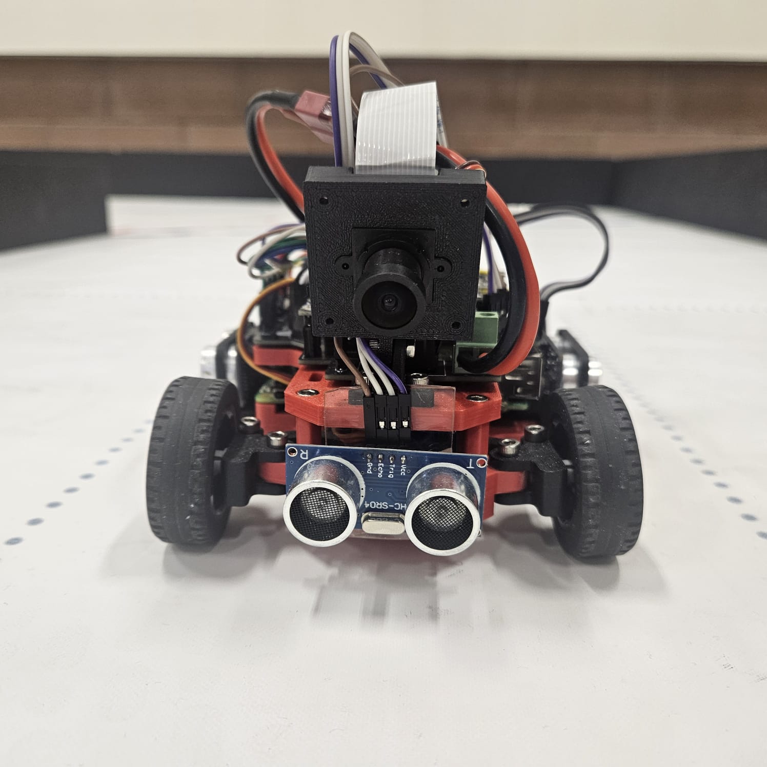
Front |
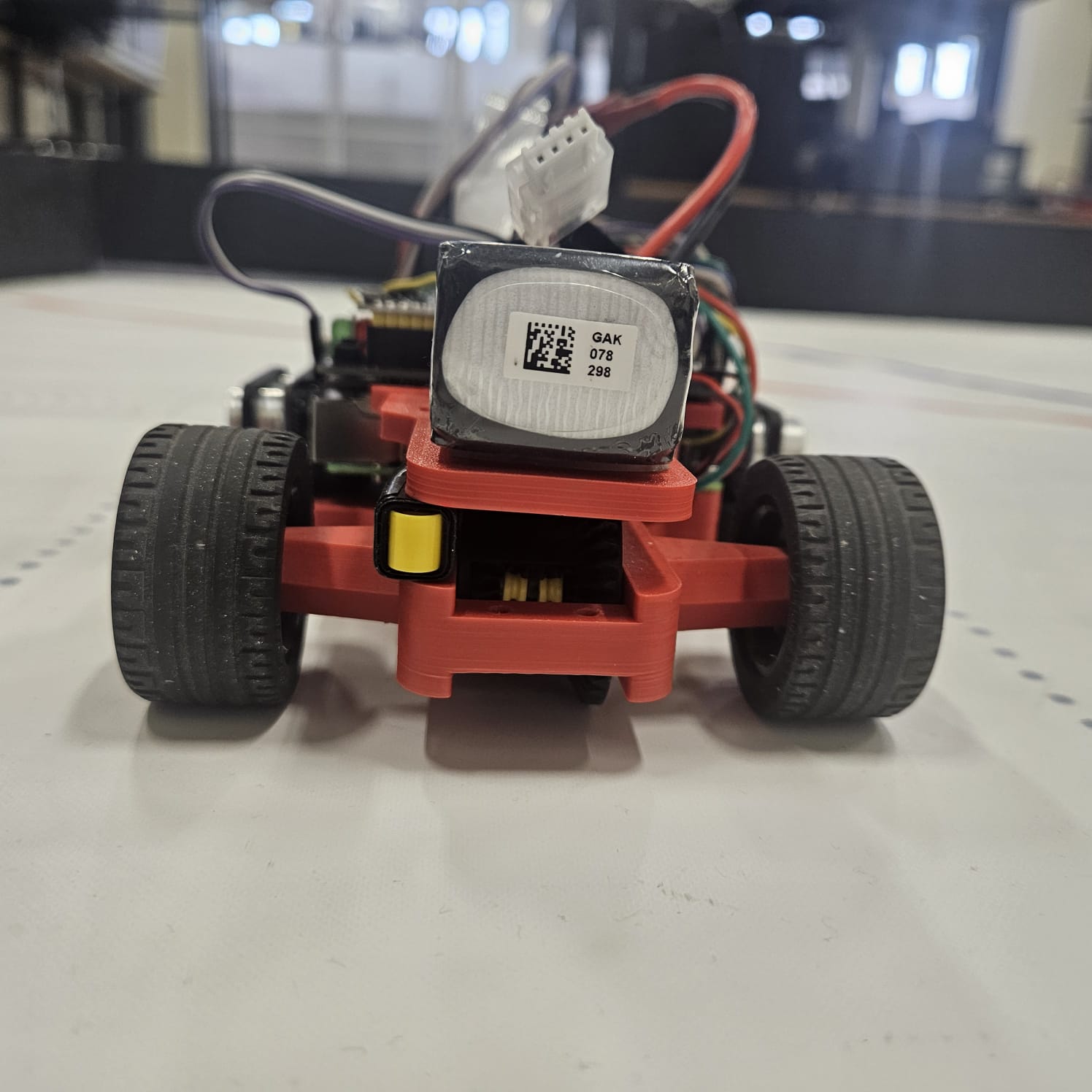
Rear |
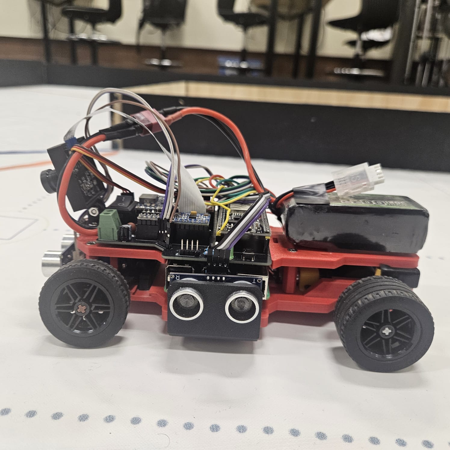
Left side |
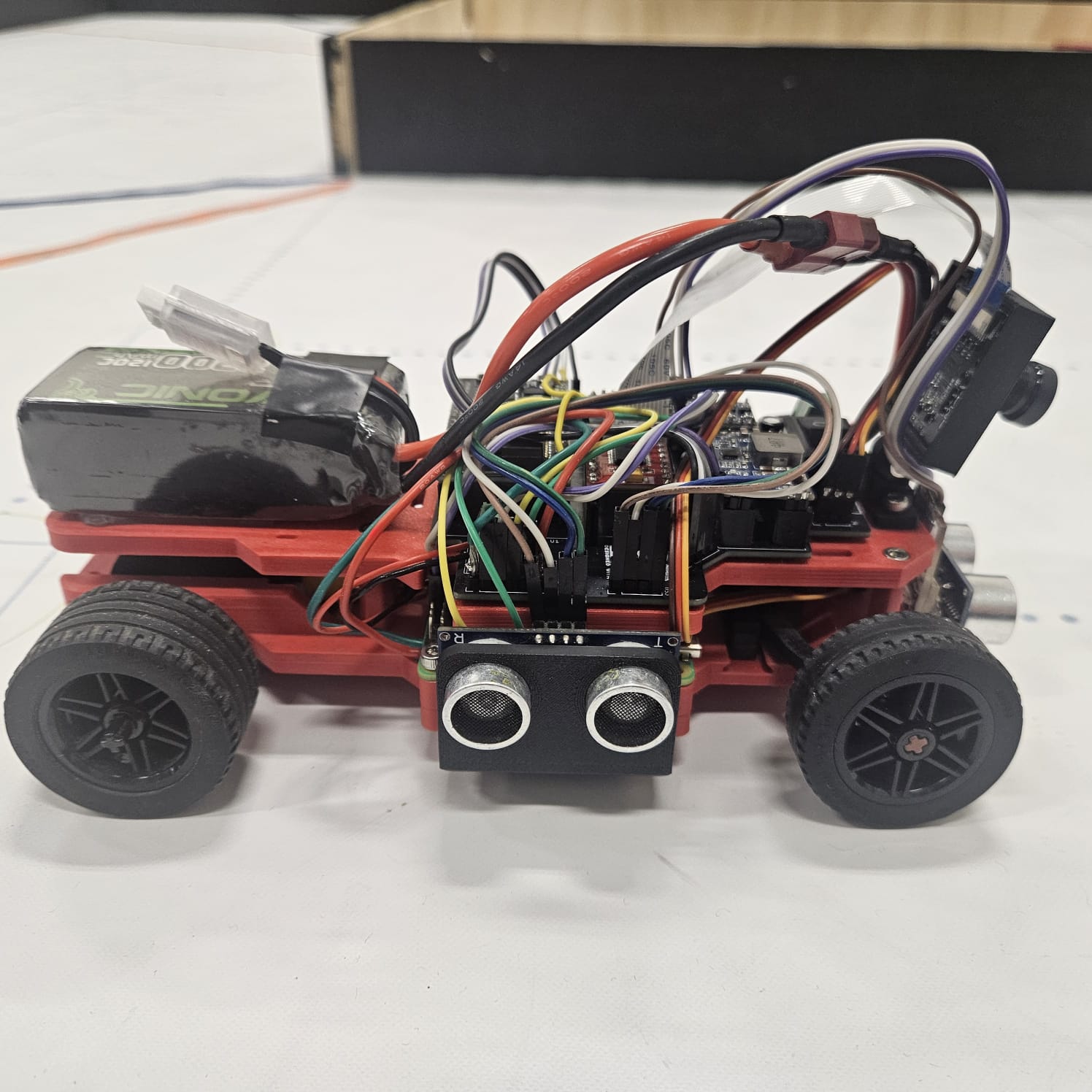
Right side |
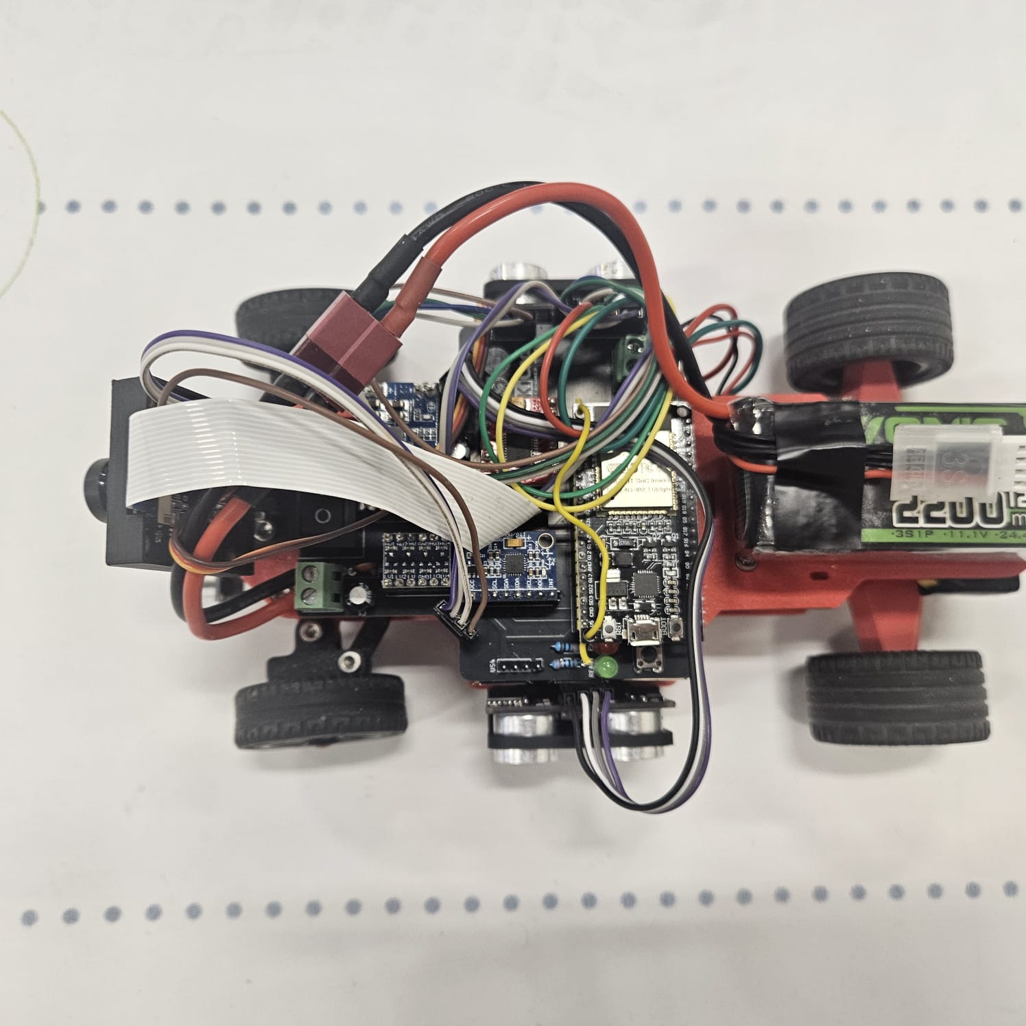
Top |
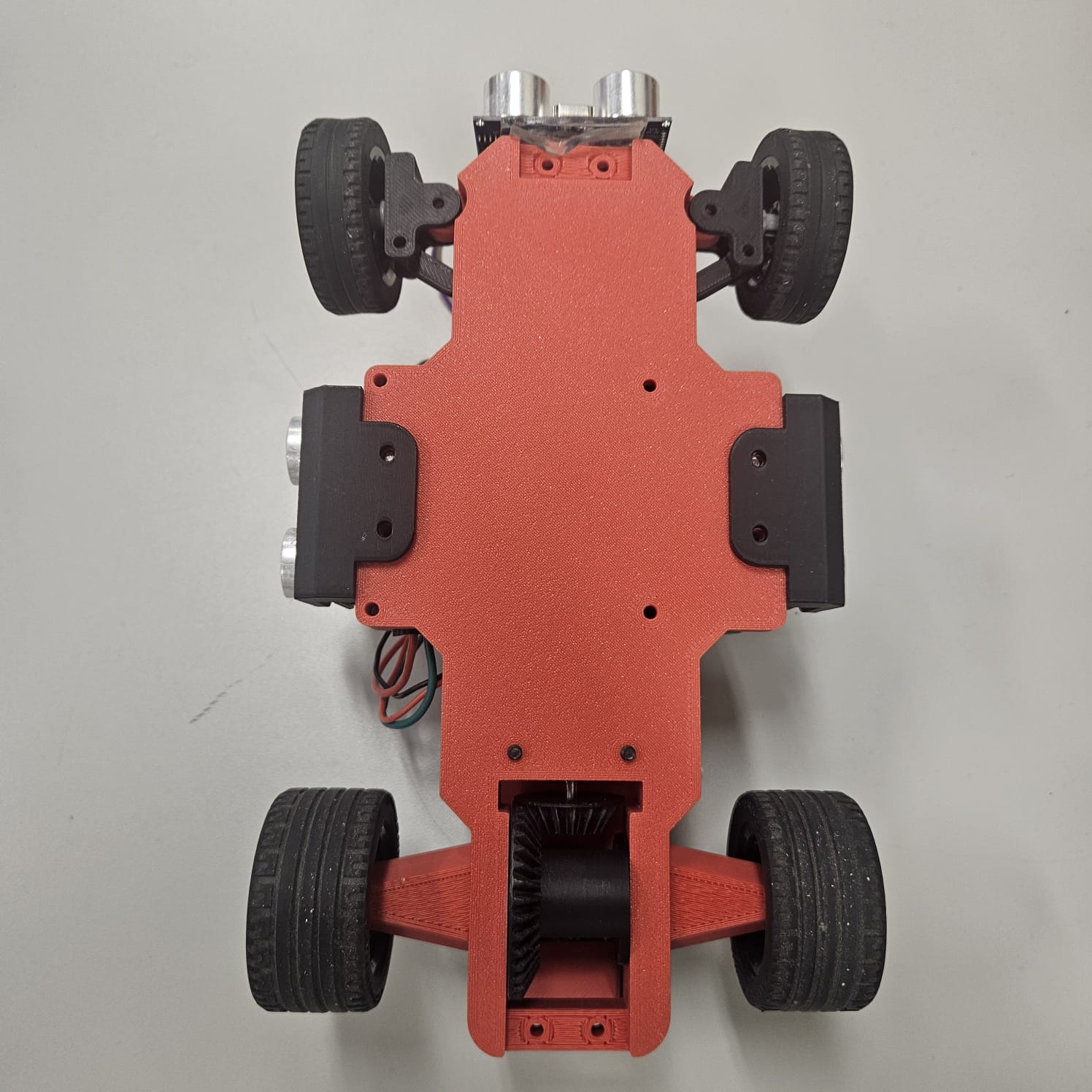
Bottom (undercarriage) |
Isometric |
Team |
---
## License
Released under the [MIT License](LICENSE) — free to use, modify and build on, code and documentation alike, with attribution.
This repository is public as required by WRO Future Engineers rules and will remain public for at least 12 months after the competition.
*WRO Future Engineers 2026 — FoxRobotics — México*