# 4. Steering System
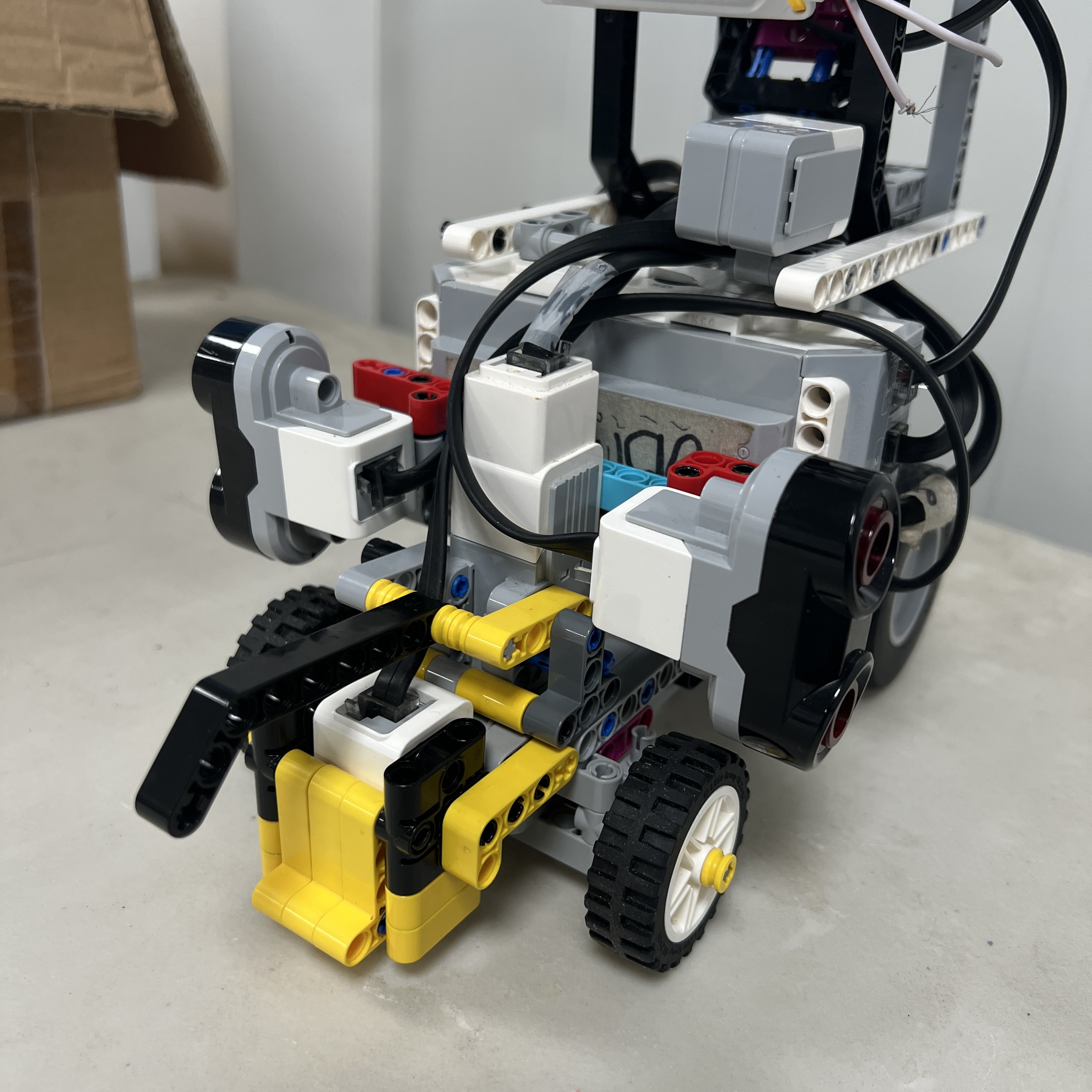 Figure 4.1. Current V4 front steering assembly viewed from above.
Piolín uses a dedicated **LEGO Mindstorms EV3 Medium Motor on Port B** to control the orientation of its two front wheels. Propulsion and steering are deliberately separated: Motor A moves the vehicle through the rear drivetrain, while Motor B changes the vehicle trajectory through the front steering mechanism.
The steering architecture can therefore be summarized as:
```text
EV3
↓
Motor B
↓
steering mechanism
↓
left + right front wheels
↓
vehicle curvature
```
Piolín does not turn by changing the speed of independently driven left and right wheels. Instead, it uses an **Ackermann-style front steering geometry**, making the mechanical behavior closer to a conventional road vehicle.
The same steering hardware is used in both WRO Future Engineers rounds. What changes between Open and Obstacles is the sensor information used by the EV3 to decide what steering command should be sent to Motor B.
---
## 4.1 Steering Actuator
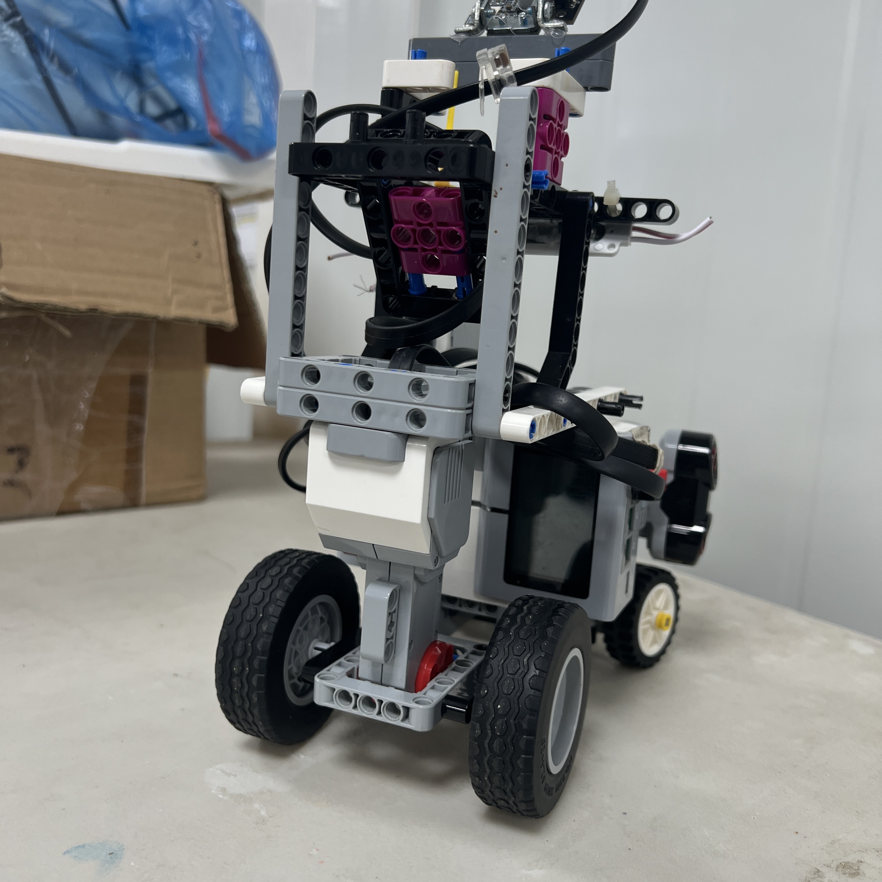 Figure 4.2. EV3 Medium Motor on Port B used exclusively for steering.
The EV3 Medium Motor provides the rotational input to the complete steering assembly.
Its task is different from Motor A:
```text
Motor A
→ vehicle propulsion
Motor B
→ steering position
```
The motor can rotate in both directions, allowing the steering assembly to move continuously between:
```text
LEFT
↔
CENTER
↔
RIGHT
```
The integrated motor encoder also provides an internal rotational reference that can be used by the software to request repeatable positions.
However, one of the most important distinctions in Piolín's steering system is:
```text
Motor B encoder angle
≠
front-wheel steering angle
```
The motor position is transformed mechanically before it reaches the wheels.
---
## 4.2 Motor B Mounting
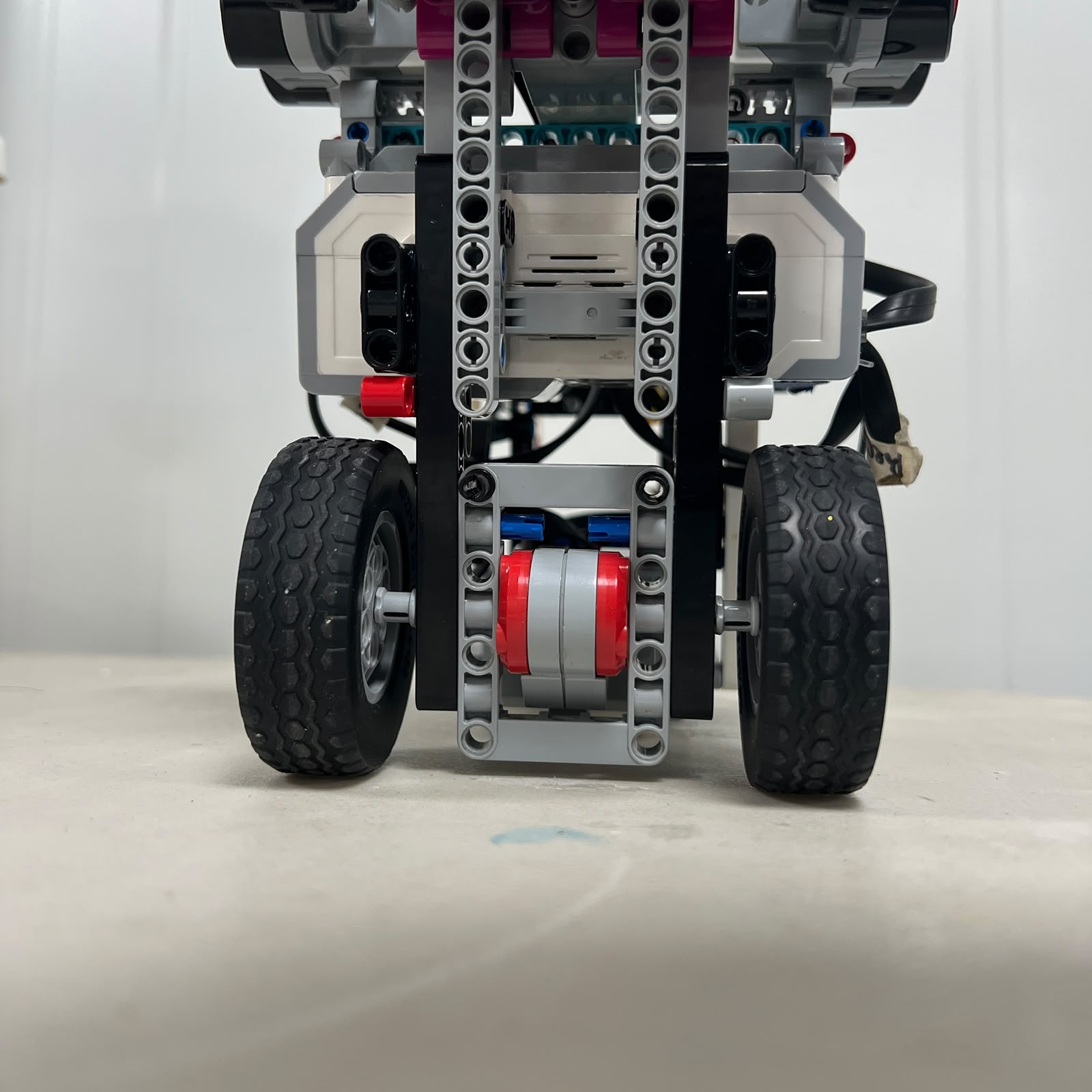 Figure 4.3. Motor B mounting structure that establishes the mechanical reference for the steering system.
Motor B must remain rigidly positioned relative to the steering linkage.
If the motor mount moves:
```text
same encoder position
↓
different linkage position
↓
different wheel orientation
```
This means the motor mount is not merely structural support. It forms part of the steering calibration reference.
A loose or flexible mount can make an otherwise correct control program appear inconsistent.
For this reason, mechanical inspection should occur before steering constants are changed in software.
---
# 4.3 Ackermann-Style Steering
Piolín's front steering system is designed around the Ackermann principle.
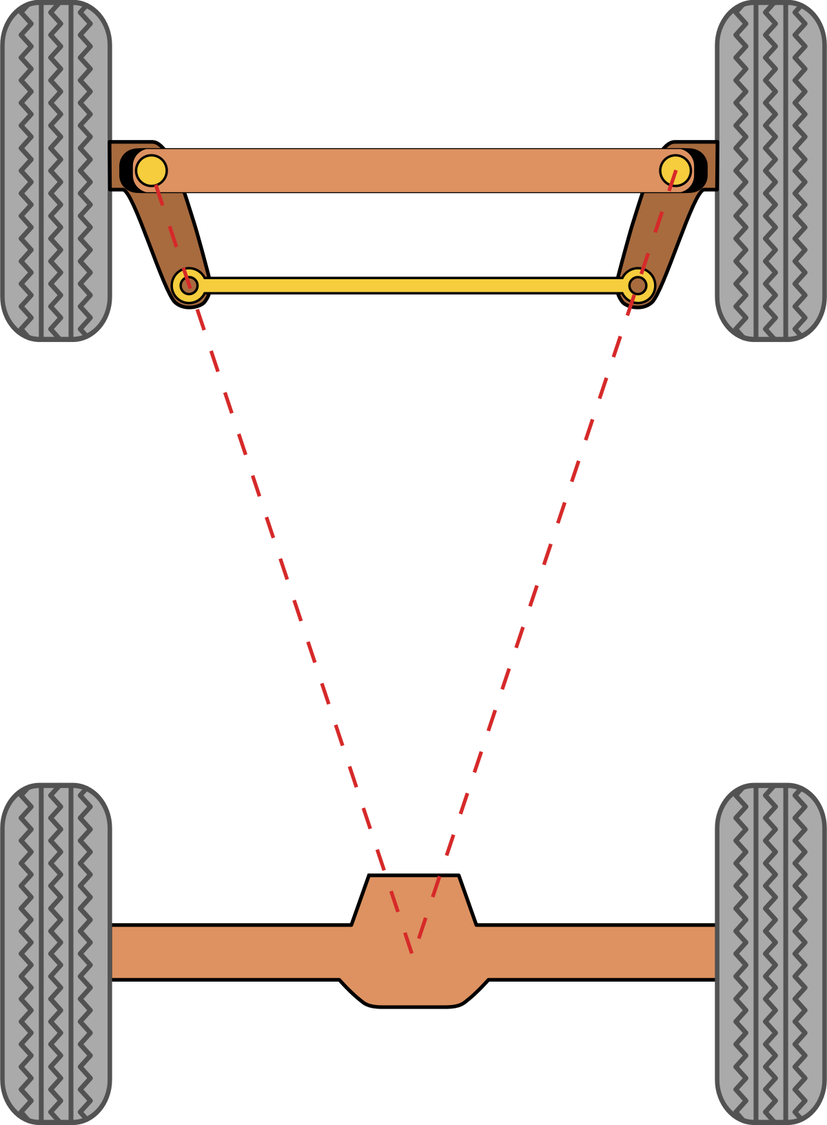 Figure 4.4. Ackermann-style geometry used as the basis of Piolín's front steering design.
When a four-wheel vehicle turns, the inner wheel follows a smaller-radius trajectory than the outer wheel.
Because the paths are different, the wheels ideally require different steering angles.
```text
INNER FRONT WHEEL
→ smaller turning radius
→ larger steering angle
OUTER FRONT WHEEL
→ larger turning radius
→ smaller steering angle
```
This is different from a parallel-steering system in which both front wheels remain at exactly the same angle.
Piolín uses an **Ackermann-style** mechanism rather than claiming mathematically perfect Ackermann geometry. Real LEGO linkage geometry, mechanical clearances, tire behavior, and packaging constraints mean the physical implementation is an approximation of the ideal model.
---
## 4.4 Ideal Ackermann Relationship
For a simplified vehicle geometry, the inner and outer steering angles can be described as:
```text
tan(δ_inner) = L / (R - T/2)
tan(δ_outer) = L / (R + T/2)
```
where:
```text
L
= wheelbase
T
= front track width
R
= turning radius measured from the vehicle centerline
δ_inner
= inner front-wheel steering angle
δ_outer
= outer front-wheel steering angle
```
Since:
```text
R - T/2
<
R + T/2
```
the expected relationship is:
```text
δ_inner
>
δ_outer
```
This mathematical model explains the purpose of the mechanism.
The final behavior of Piolín, however, should be evaluated using measurements from the actual V4 robot rather than assuming the LEGO linkage perfectly reproduces the theoretical geometry.
---
## 4.5 Physical Front Geometry
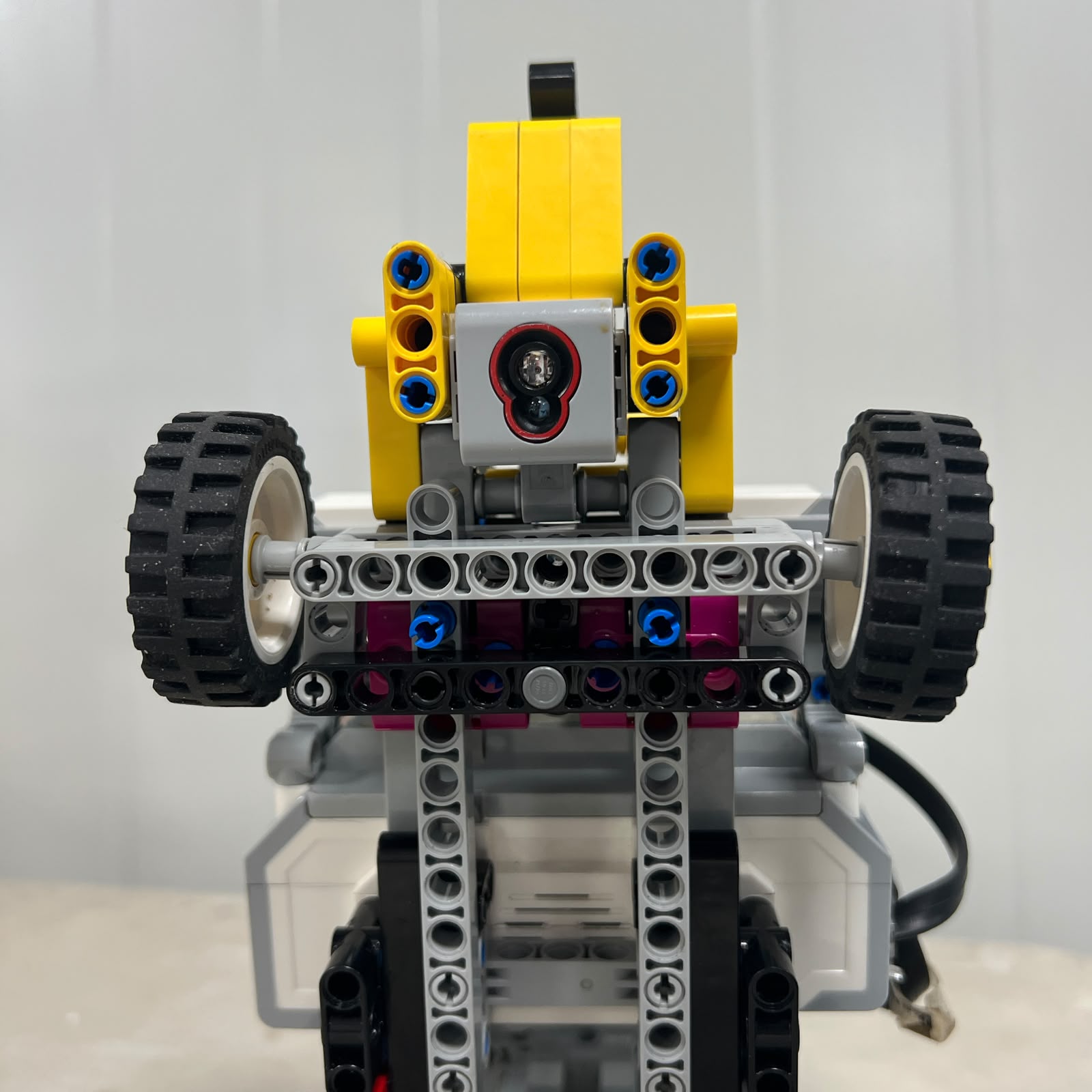 Figure 4.5. Front view of Piolín's current steering structure, wheel pivots, and linkage geometry.
The front assembly contains several passive mechanical elements in addition to Motor B.
These include:
```text
wheel pivots
steering arms
links
axles
pins
structural supports
```
Together, these elements transform one motor rotation into coordinated movement of two separate wheels.
This is why steering behavior cannot be described using Motor B alone.
The actual trajectory depends on the complete chain:
```text
Motor B
↓
mechanical transmission
↓
steering links
↓
wheel pivots
↓
left and right wheel angles
↓
vehicle path
```
---
# 4.6 Mechanical Steering Center
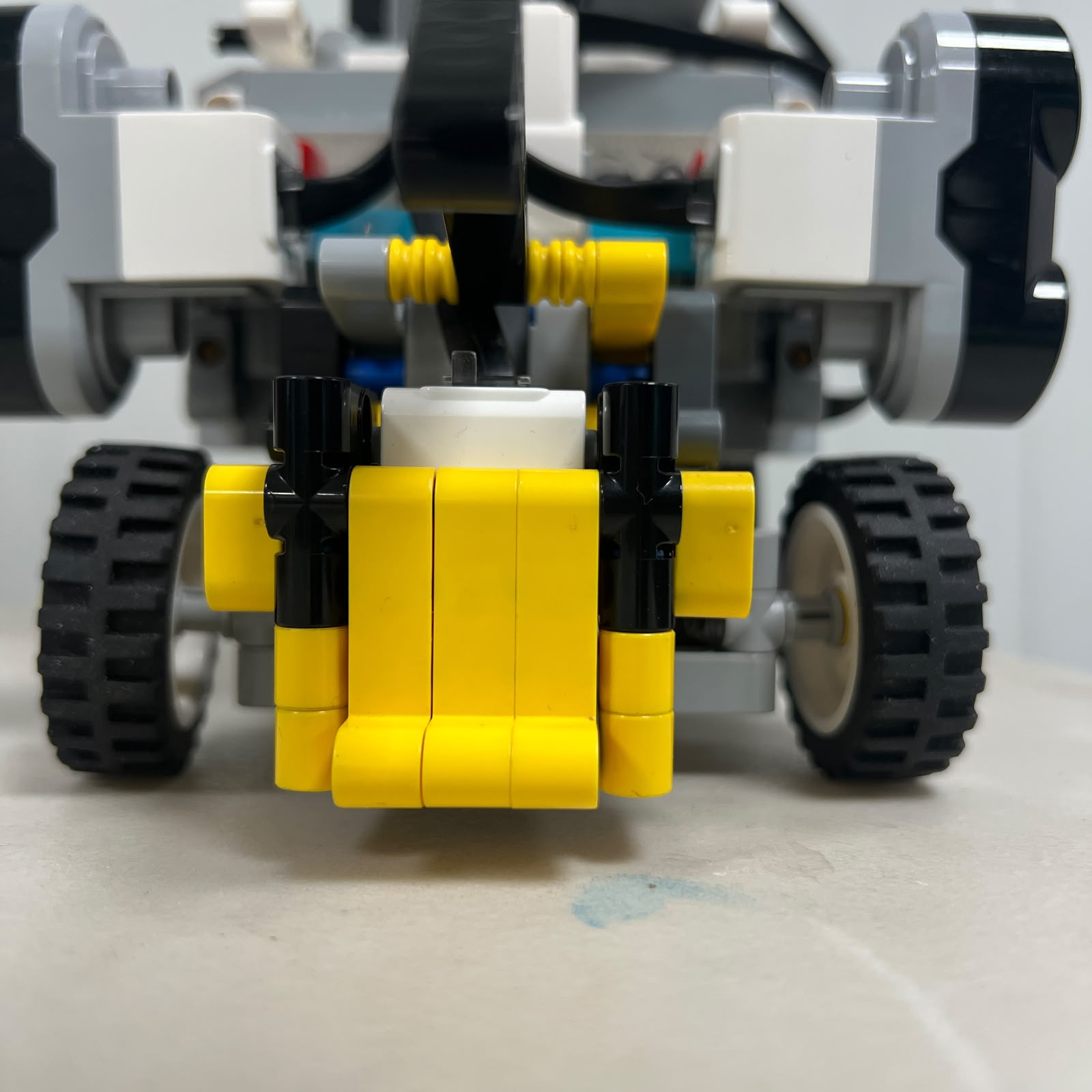 Figure 4.6. Current mechanical center position used as the reference for straight driving.
A repeatable mechanical center is fundamental to Piolín's navigation.
The desired condition is:
```text
Motor B center reference
↓
steering linkage centered
↓
front wheels approximately straight
↓
vehicle capable of stable straight motion
```
If the wheels are mechanically offset, Piolín can drift even if the EV3 requests a neutral steering command.
A persistent steering bias should therefore not immediately be corrected by adding a software offset.
The preferred diagnostic order is:
```text
inspect linkage
↓
verify wheel alignment
↓
verify Motor B mount
↓
find mechanical center
↓
perform straight-driving test
↓
apply small software correction only if needed
```
Mechanical alignment should solve mechanical errors whenever possible.
---
# 4.7 Left Steering Limit
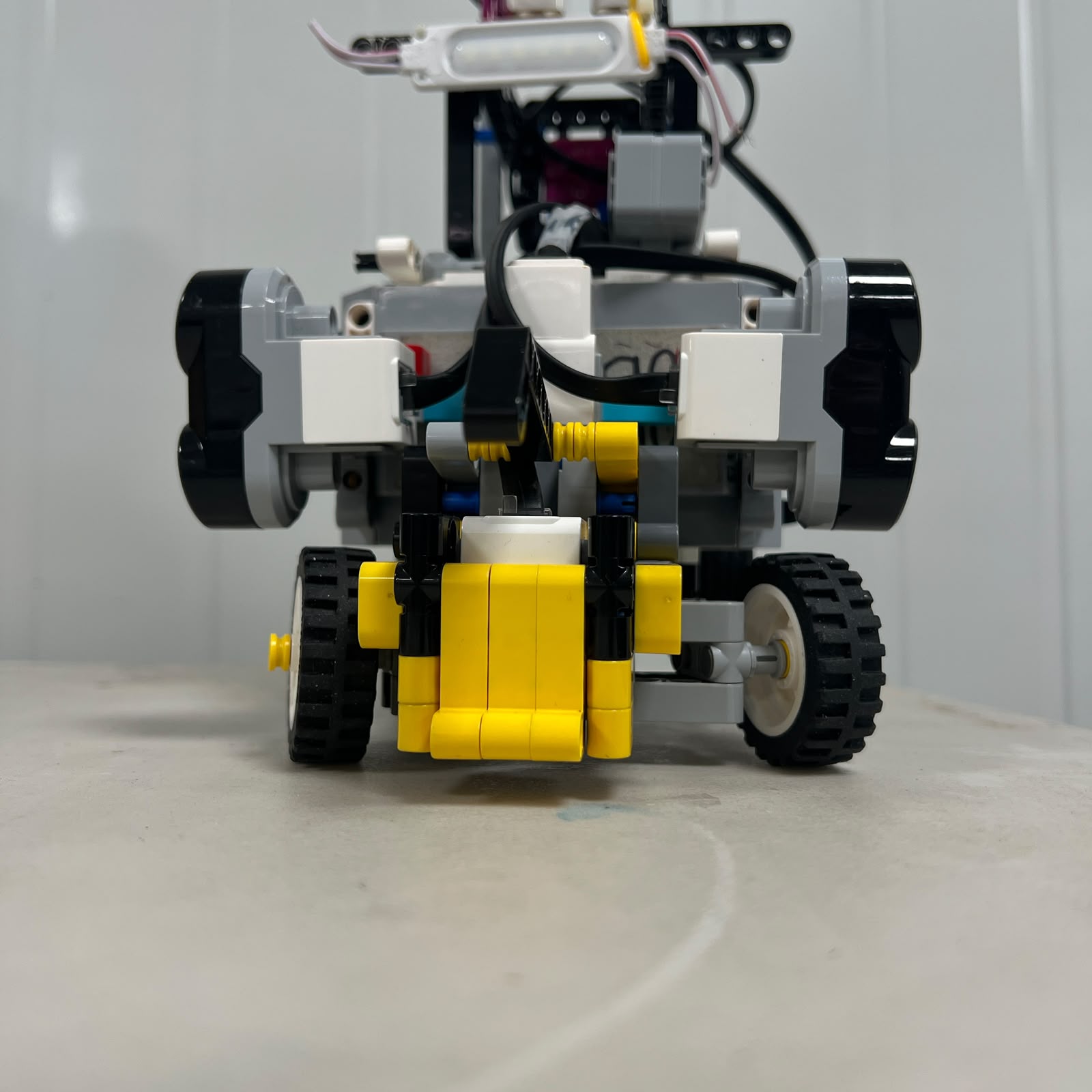 Figure 4.7. Current left-side steering limit of the V4 mechanism.
The steering mechanism has a finite physical range.
The useful left limit should occur before the linkage begins to:
```text
bind
contact the chassis
create excessive friction
force Motor B against a mechanical stop
```
The maximum possible motor rotation is therefore not necessarily the maximum useful steering command.
Software steering limits should remain inside the mechanically usable range.
---
# 4.8 Right Steering Limit
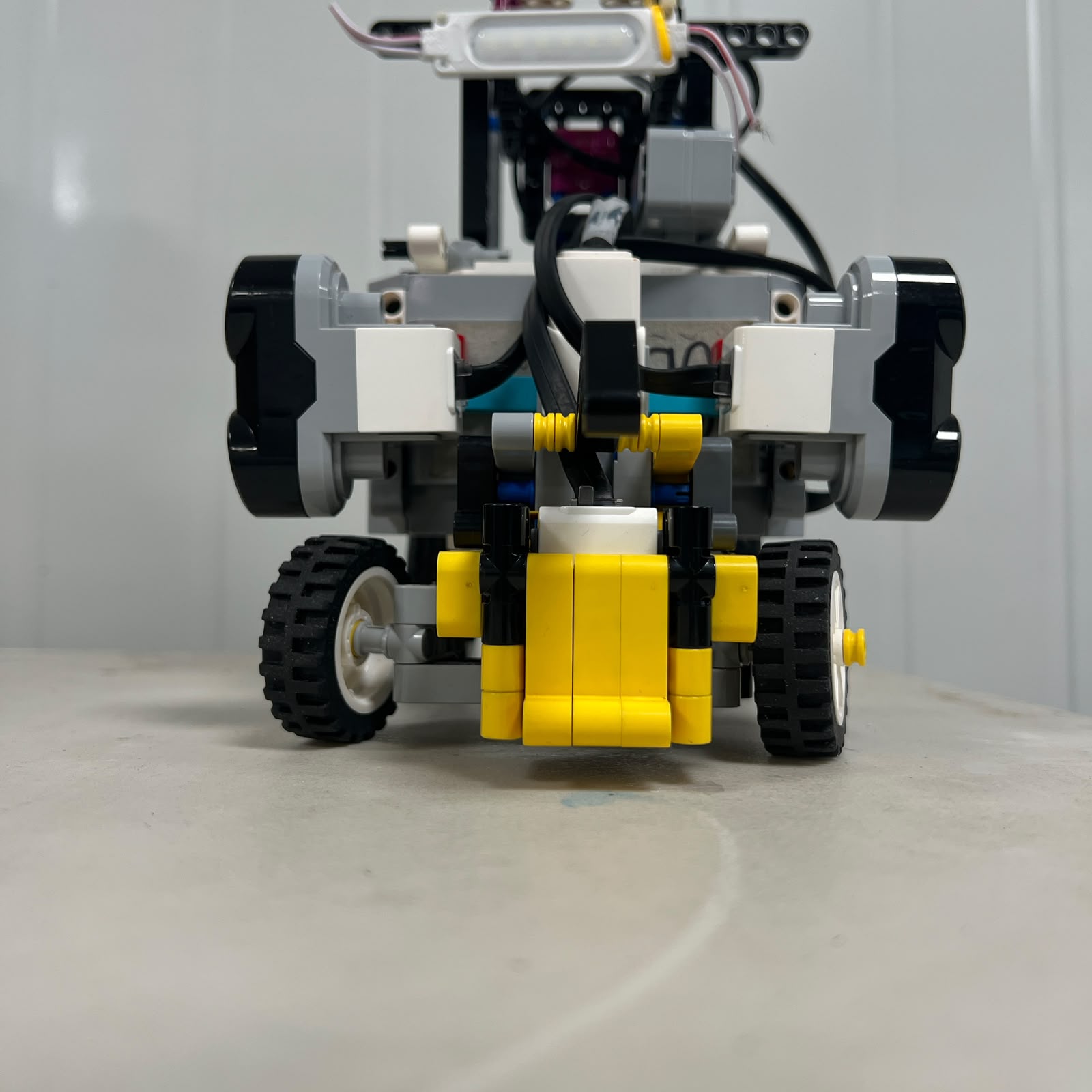 Figure 4.8. Current right-side steering limit of the V4 mechanism.
The same principle applies to the right side.
Piolín should not automatically assume that:
```text
maximum left command
=
maximum right command
```
in terms of physical wheel angle.
Small asymmetries can appear because of:
```text
linkage geometry
LEGO mechanical tolerances
pivot friction
assembly position
mechanical play
```
Left and right steering behavior should therefore be measured separately.
---
# 4.9 Steering Angle Reference
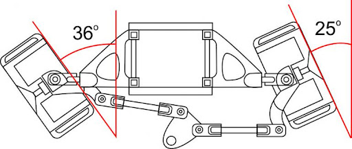 Figure 4.9. Physical steering-angle reference used to document the relationship between the front wheels and the steering mechanism.
The most useful steering calibration is not simply:
```text
Motor B degrees
```
but rather:
```text
Motor B position
↓
measured left wheel angle
+
measured right wheel angle
```
A future quantitative calibration table can use the following structure:
| Motor B Position | Left Wheel Angle | Right Wheel Angle | Vehicle Condition |
| :---: | :---: | :---: | :--- |
| Left limit | — | — | Maximum useful left |
| Intermediate left | — | — | Partial left |
| Center | — | — | Straight reference |
| Intermediate right | — | — | Partial right |
| Right limit | — | — | Maximum useful right |
The numerical values should be added only after they are physically measured on the current V4 steering system.
---
# 4.10 Dynamic Steering Motion
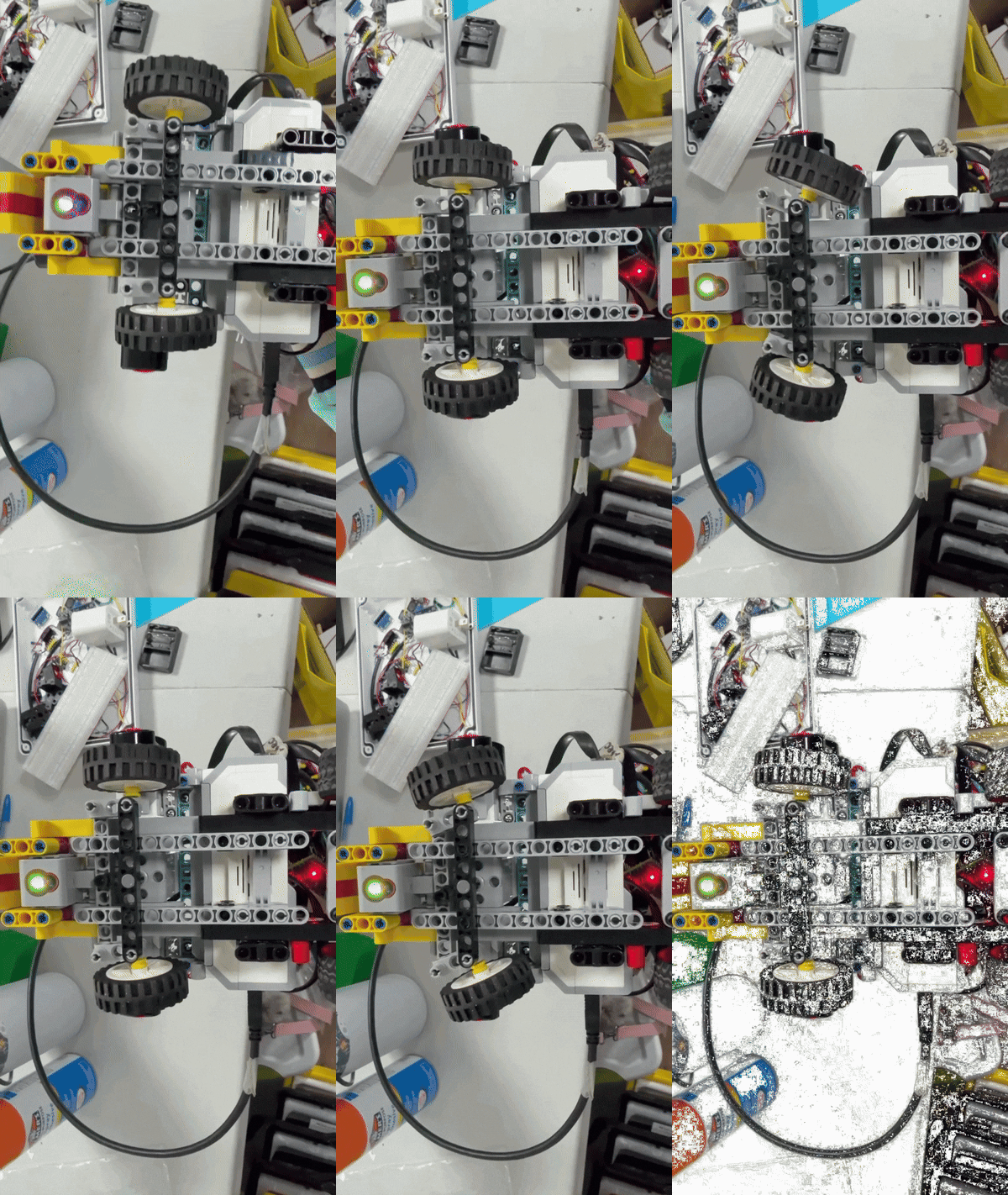 Figure 4.10. Dynamic steering movement demonstrating the complete usable range of the mechanism.
The animation reveals something that static images cannot show as clearly: steering requires physical time.
The actual response sequence is:
```text
EV3 requests new steering position
↓
Motor B begins moving
↓
linkage begins moving
↓
front-wheel angles change
↓
vehicle curvature changes
```
This means a software steering command does not change Piolín's trajectory instantaneously.
While the mechanism is moving, Motor A may continue propelling the robot forward.
Steering response time therefore affects:
```text
corner entry
corner exit
wall correction
pillar avoidance
countersteering
parking
```
---
# 4.11 Steering Response and Vehicle Speed
Steering and propulsion cannot be tuned completely independently.
Consider one identical Motor B movement.
At lower vehicle speed:
```text
less distance is traveled
while steering changes
```
At higher vehicle speed:
```text
more distance is traveled
while steering changes
```
Therefore:
```text
same steering command
+
different Motor A speed
=
different physical trajectory
```
This relationship explains why a corner that works reliably at one speed may become too wide when propulsion speed increases.
Likewise, an obstacle maneuver that works at low speed may react too late at competition speed.
The complete steering calibration must therefore include dynamic vehicle testing.
---
# 4.12 Steering Resolution vs. Steering Authority
The mechanical linkage creates a trade-off between steering range and steering sensitivity.
A design can prioritize:
```text
larger physical wheel movement
per Motor B degree
```
which provides stronger turning authority, but also makes small motor-command changes more significant.
Alternatively, a linkage can provide:
```text
smaller wheel movement
per Motor B degree
```
which improves command resolution but can reduce maximum available curvature.
Piolín therefore requires a compromise between:
```text
tight-enough corners
fine straight-line corrections
fast obstacle reactions
mechanical stability
```
The final linkage should provide enough authority for corners and obstacles without making small steering corrections excessively aggressive.
---
# 4.13 Steering Pivots
The front wheels rotate around mechanical pivots.
Those pivots must provide:
```text
low enough friction
```
for Motor B to move the wheels efficiently, while also providing:
```text
sufficient structural rigidity
```
to preserve repeatable wheel geometry.
A pivot that is too tight can cause:
```text
slow steering response
increased Motor B load
incomplete movement
```
A pivot with excessive clearance can cause:
```text
wheel-angle uncertainty
mechanical oscillation
poor repeatability
```
The correct solution lies between these extremes.
---
# 4.14 Mechanical Play and Backlash
LEGO mechanical assemblies contain small clearances between parts.
Potential sources include:
```text
pins
axles
pivot holes
steering links
motor output connections
```
These clearances become especially important when steering direction changes.
For example:
```text
Motor B moving RIGHT
↓
software requests LEFT
↓
Motor B reverses
↓
mechanical clearance is taken up
↓
front wheels begin moving LEFT
```
The controller changes direction immediately.
The physical wheels do not.
During the delay, Motor A may continue moving the vehicle forward.
This is why even relatively small mechanical play can become visible as a larger trajectory error.
---
# 4.15 Steering Repeatability
A useful steering mechanism should return close to the same physical position when the same command is repeated.
One practical test sequence is:
```text
CENTER
↓
LEFT
↓
CENTER
↓
RIGHT
↓
CENTER
```
and repeat the cycle several times.
The test should evaluate whether the wheels return to approximately the same center after approaching from both directions.
This is particularly important because backlash can produce:
```text
center approached from left
```
and:
```text
center approached from right
```
as slightly different physical states.
No numerical repeatability claim should be published until this test is measured.
---
# 4.16 Steering Symmetry
Piolín should also compare left and right steering.
The test can use equal-magnitude Motor B positions:
```text
-X
```
and:
```text
+X
```
and then compare the resulting wheel geometry and vehicle trajectory.
The purpose is not necessarily to prove perfect symmetry.
The purpose is to determine whether:
```text
one common steering calibration
```
is sufficient, or whether:
```text
left and right require slightly different treatment
```
because of real mechanical differences.
---
# 4.17 Straight-Line Steering
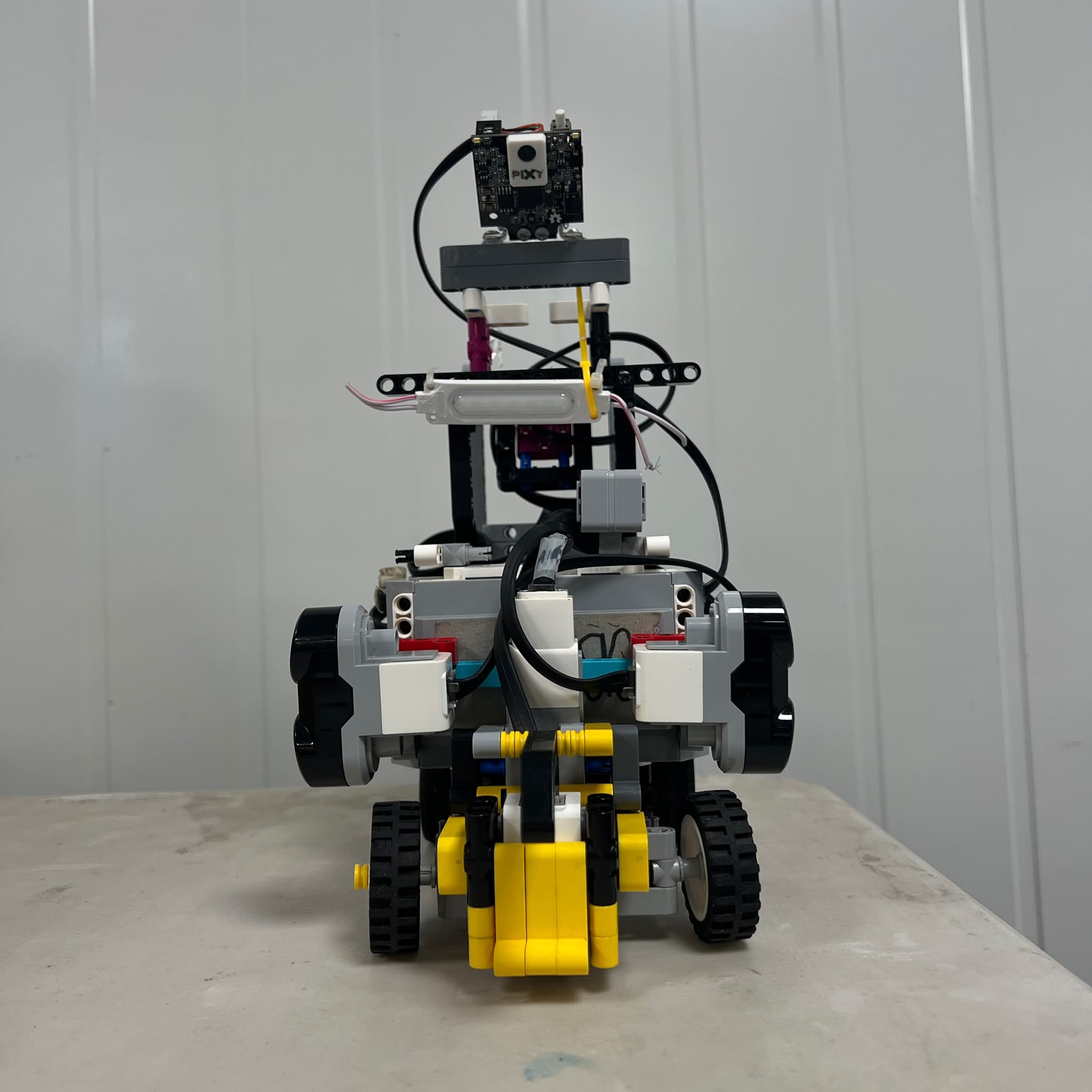 Figure 4.11. Front view showing the relationship between steering-center geometry and the complete vehicle.
During a stable straight section, Motor B should normally remain relatively close to its center reference.
The desired behavior is:
```text
small trajectory error
→ small steering correction
```
rather than:
```text
small trajectory error
→ large steering command
```
If corrections become too strong or occur too late, Piolín can enter an oscillation:
```text
steer left
↓
cross desired path
↓
steer right
↓
cross desired path
↓
repeat
```
This produces the zig-zag behavior observed during development when steering authority, timing, and sensor correction are not properly balanced.
The objective is not to prevent Motor B from correcting the vehicle. It is to prevent the correction itself from becoming the next error.
---
# 4.18 Steering During the Open Challenge
During Open, the steering mechanism receives its commands from navigation logic based primarily on:
```text
S1
→ Gyro
S2
→ Left Ultrasonic
S3
→ Right Ultrasonic
S4
→ Color Sensor
```
The mechanical steering hardware does not know which sensor caused the command.
The EV3 interprets the sensor information and determines the required Motor B response.
During straight driving:
```text
ultrasonic geometry
→ lateral-position information
gyro
→ heading information
Motor B
→ correction
```
The objective is to keep steering close to center when the robot is already stable and increase steering authority only when the course geometry requires it.
---
# 4.19 Open Corner Steering
Open corners require a temporary increase in steering curvature.
The conceptual sequence is:
```text
stable straight
↓
corner condition detected
↓
Motor B moves away from center
↓
vehicle begins turning
↓
gyro + geometry indicate corner progress
↓
Motor B begins returning
↓
lateral wall geometry is reacquired
↓
straight steering resumes
```
The steering system therefore needs both:
```text
a turn-entry strategy
```
and:
```text
a turn-release strategy
```
A successful corner cannot be defined only by the maximum steering angle.
---
## 4.20 Corner Entry
If steering begins too late:
```text
Piolín travels too far forward
↓
turn starts late
↓
outer collision risk increases
```
If steering begins too early:
```text
Piolín cuts inward
↓
inner clearance decreases
```
The correct entry behavior therefore depends on:
```text
starting position
vehicle heading
Motor A speed
Motor B response time
track geometry
```
This is why Open corner tuning must be performed using the complete moving robot.
---
## 4.21 Corner Exit
The steering release is equally important.
If Motor B remains strongly turned for too long:
```text
Piolín continues rotating
→ exits too far inward
```
If Motor B returns to center too early:
```text
Piolín under-rotates
→ exits too far outward
```
A useful corner must leave Piolín with:
```text
reasonable heading
reasonable lateral position
reduced steering angle
usable wall geometry
```
for the next straight.
---
# 4.22 Clockwise and Counterclockwise Steering
The physical steering mechanism remains unchanged regardless of course direction.
The Color Sensor determines the initial Open direction:
```text
BLUE first
→ counterclockwise
ORANGE first
→ clockwise
```
The two ultrasonic sensors always remain physically:
```text
S2 = LEFT
S3 = RIGHT
```
For counterclockwise navigation:
```text
S2 LEFT
→ inner side
S3 RIGHT
→ outer side
```
For clockwise navigation:
```text
S3 RIGHT
→ inner side
S2 LEFT
→ outer side
```
Only the logical interpretation changes.
Motor B still uses the same mechanical left and right steering directions.
---
# 4.23 Steering During Obstacles
The same Motor B and Ackermann mechanism are retained during the Obstacle Challenge.
What changes is the primary perception source.
```text
OPEN
→ Gyro + ultrasonic geometry
OBSTACLES
→ Pixy2.1 + ultrasonic geometry
```
This is a major engineering advantage because steering hardware does not need to be rebuilt for a different round.
The same:
```text
center
limits
linkage
pivots
wheel geometry
```
continue to apply.
---
# 4.24 Red Pillar Steering
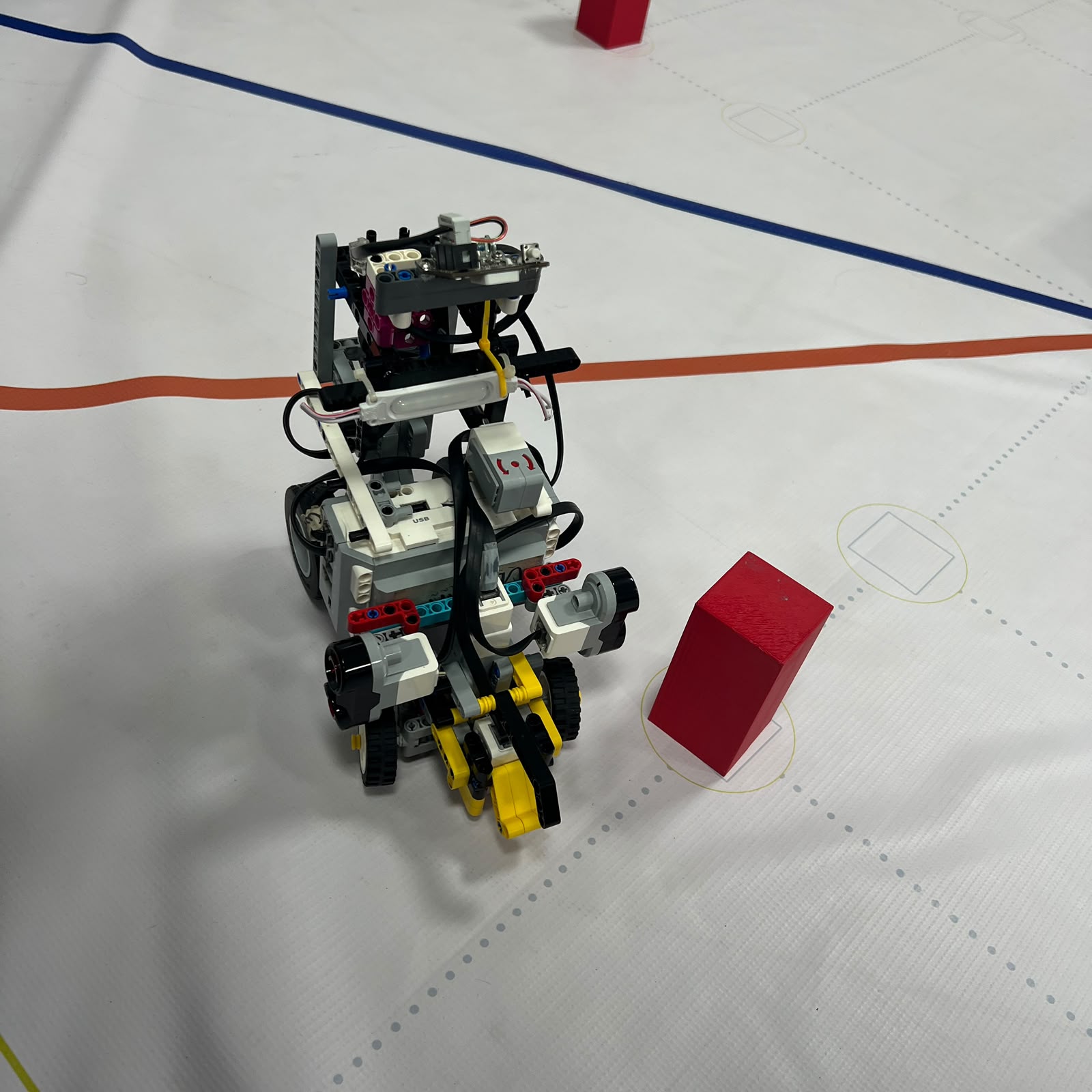 Figure 4.12. Piolín executing a red-pillar maneuver during obstacle testing.
The competition rule requires:
```text
RED
→ pass RIGHT
```
The steering objective is therefore to create a trajectory that places Piolín on the required side of the pillar.
However:
```text
RED
```
does not mean:
```text
hold maximum right steering
```
A complete maneuver can contain:
```text
approach
initial steering
side-pass trajectory
pillar clearance
countersteering
recovery
```
The correct wheel angle changes throughout the maneuver.
---
# 4.25 Green Pillar Steering
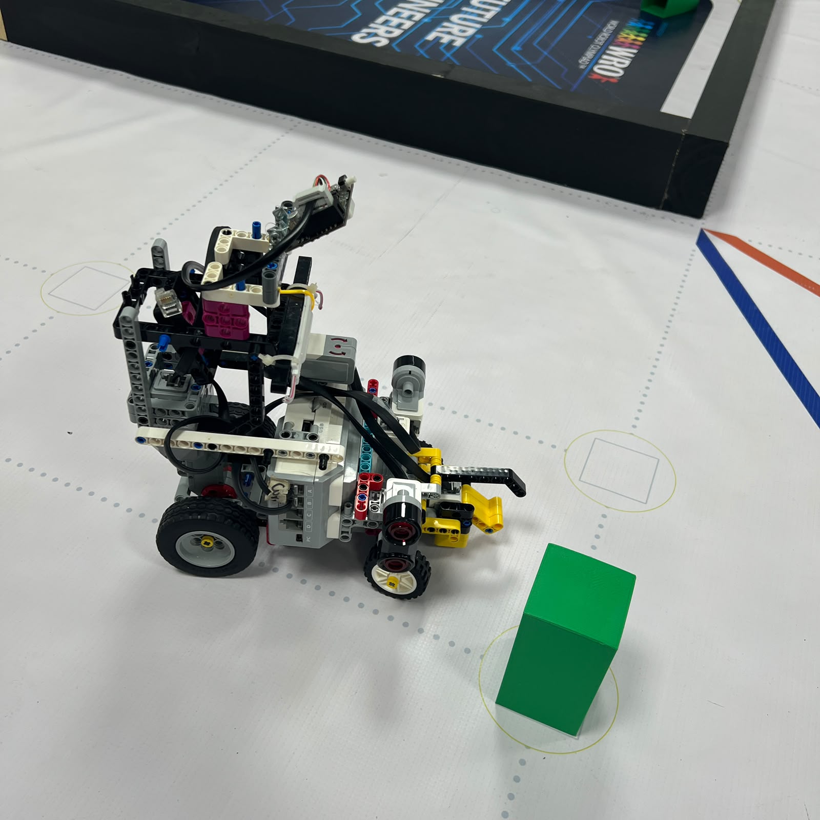 Figure 4.13. Piolín executing a green-pillar maneuver during obstacle testing.
The Green rule is:
```text
GREEN
→ pass LEFT
```
The mechanical objective is opposite to Red, but the physical calibration should not automatically assume mathematically identical left and right values.
Real steering systems can contain small asymmetries.
Therefore obstacle tuning should validate:
```text
red / right maneuver
```
and:
```text
green / left maneuver
```
independently.
---
# 4.26 Countersteering
Countersteering is critical after Piolín has generated enough lateral movement to clear a pillar.
Consider a right-side maneuver:
```text
steer RIGHT
↓
Piolín develops rightward trajectory
↓
pillar is cleared
↓
steer LEFT
↓
rightward trajectory is reduced
↓
steering returns toward normal
```
Without sufficient countersteering, Piolín can pass the obstacle successfully and then continue into the wall.
With countersteering that begins too early, it can return toward the pillar.
The correct countersteering point therefore depends on the obstacle state, vehicle speed, and surrounding geometry.
---
# 4.27 Post-Obstacle Recovery
A successful obstacle maneuver should not end at:
```text
pillar no longer directly ahead
```
It should end when Piolín has returned to a usable state for continued navigation.
The desired transition is:
```text
obstacle steering
↓
pillar clearance
↓
countersteering
↓
ultrasonic geometry becomes useful again
↓
Motor B approaches normal correction range
```
This prevents one successful avoidance from creating a poor approach to the next obstacle.
---
# 4.28 Steering and Pixy2.1 Geometry
During Obstacles, steering also changes the camera viewpoint.
When Motor B changes the trajectory:
```text
front-wheel angle changes
↓
vehicle yaw changes
↓
Pixy orientation changes
↓
pillar position in the camera image changes
```
This means a change in Pixy `x` can partly result from the robot's own steering motion.
The obstacle software should therefore avoid interpreting every movement of the visual block as independent movement of the physical pillar.
Vision and steering form a feedback loop.
---
# 4.29 Steering and Ultrasonic Geometry
The lateral ultrasonic sensors are also affected by vehicle yaw.
The sensors remain physically:
```text
S2 = LEFT
S3 = RIGHT
```
but the way their beams intersect the wall changes when Piolín rotates.
During approximately parallel straight driving:
```text
ultrasonic distance
≈ useful lateral reference
```
During a strong steering maneuver:
```text
vehicle orientation changes
→ wall intersection geometry changes
```
A rapid ultrasonic-distance change during a corner therefore does not necessarily represent pure lateral movement.
This is another reason the controller needs awareness of the current steering state.
---
# 4.30 Steering and Reverse Motion
When Piolín moves backward, the same front-wheel orientation produces a different vehicle trajectory from forward motion.
The steering system itself does not change, but the vehicle kinematics do.
Reverse steering may be used during:
```text
recovery
repositioning
parking
```
but reverse maneuvers should be calibrated separately rather than assuming every forward-steering behavior transfers directly to reverse motion.
---
# 4.31 Steering During Parking
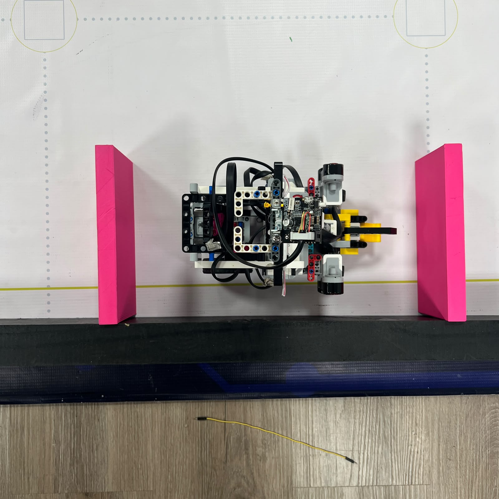 Figure 4.14. Parking area used to develop the final controlled positioning sequence.
Parking requires controlled steering at low positional margins.
The maneuver can require:
```text
approach alignment
controlled steering
forward or reverse displacement
countersteering
final wheel alignment
```
The final parking strategy is still under development, so this document does not claim one final validated steering sequence.
The useful engineering requirement is that parking should depend on controlled vehicle state and displacement rather than arbitrary steering timing alone.
---
# 4.32 Mechanical Steering Inspection
Before modifying software because Piolín appears to steer incorrectly, the front mechanism should be inspected.
A useful procedure is:
```text
Motor B secure?
↓
linkage fully connected?
↓
left pivot free?
↓
right pivot free?
↓
center visually correct?
↓
left range free?
↓
right range free?
↓
no mechanical interference?
```
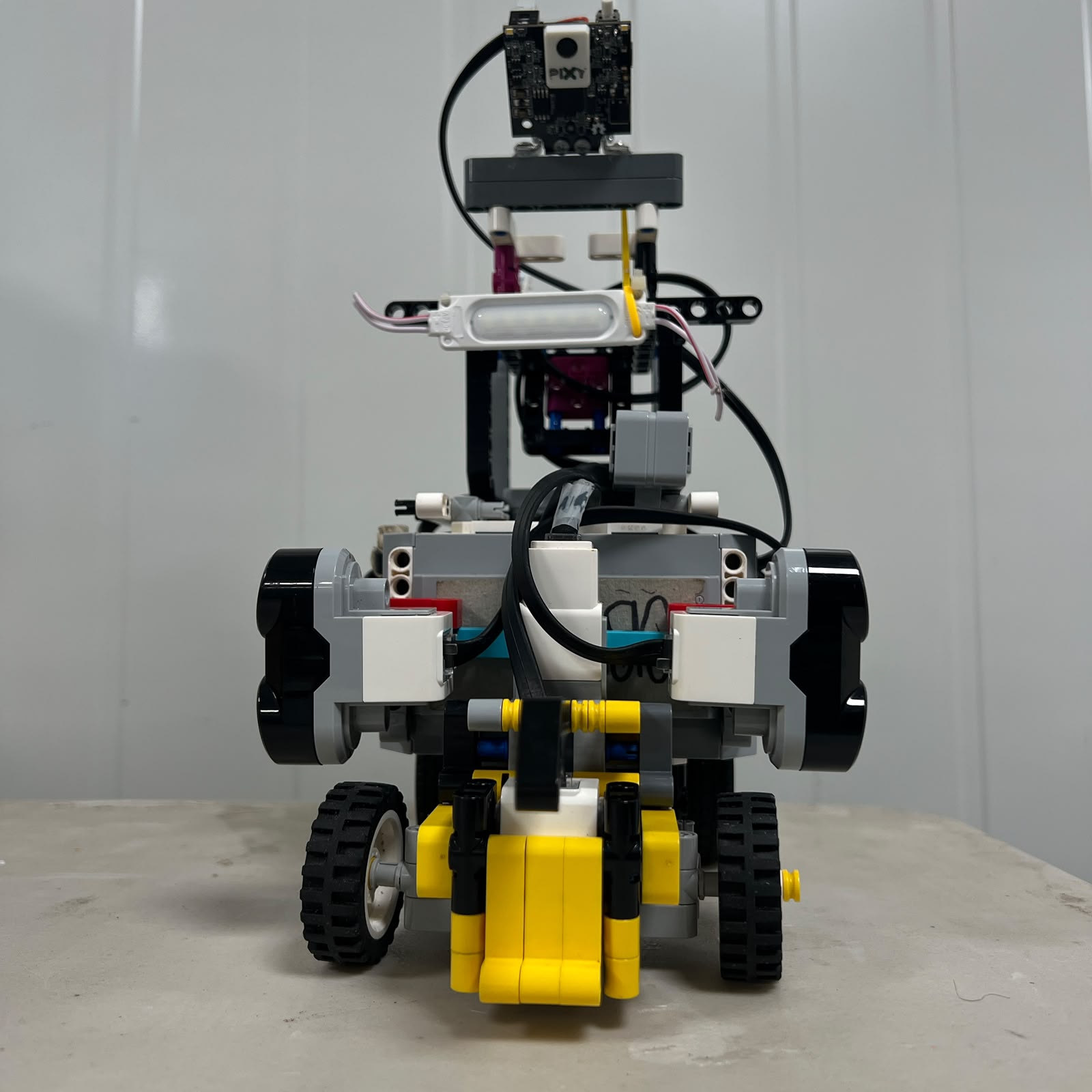 Figure 4.15. Front chassis structure surrounding the steering mechanism and wheel supports.
This inspection should be performed after significant mechanical changes and before important competition testing.
---
# 4.33 Steering Failure Diagnosis
| Observed Behavior | Possible Cause |
| :--- | :--- |
| Piolín always drifts left | Mechanical center, wheel alignment, controller bias |
| Piolín always drifts right | Mechanical center, wheel alignment, controller bias |
| Left steering works but right does not | Binding, interference, linkage problem |
| Right steering works but left does not | Binding, interference, linkage problem |
| Steering response is delayed | Pivot friction, mechanical play, motor response |
| Steering oscillates left-right | Excessive correction, delayed response, speed |
| Wheels fail to return to same center | Backlash, loose linkage, calibration |
| Motor B struggles near full steering | Mechanical stop or excessive friction |
| Left and right corners behave differently | Mechanical asymmetry or separate tuning need |
| Obstacle avoidance works but recovery fails | Countersteering timing or magnitude |
| Steering works while lifted but poorly on track | Tire load, pivot friction, structural deformation |
| Behavior suddenly changes with same software | Loose Motor B mount, moved linkage, wheel alignment |
This table helps distinguish:
```text
mechanical problem
```
from:
```text
software problem
```
before controller values are changed.
---
# 4.34 Mechanical vs. Software Steering
Piolín's steering can be divided into two interacting layers.
### Mechanical steering
```text
Motor B
motor mount
linkage
pivots
wheel geometry
physical limits
mechanical play
```
### Software steering
```text
target command
control error
correction magnitude
corner timing
obstacle strategy
countersteering
recovery
```
The mechanical system determines what vehicle motion is physically possible.
The software determines when and how that capability should be used.
Neither layer can compensate completely for a poorly functioning other layer.
---
# 4.35 Steering Alternatives
Several steering architectures could have been used.
| Steering Architecture | Advantage | Limitation for Piolín |
| :--- | :--- | :--- |
| Differential steering | Simple mechanical turning | Requires independent left/right propulsion and tire scrub |
| Skid steering | Can rotate aggressively at low speed | Higher lateral tire friction |
| Parallel front steering | Simpler front geometry | Does not account for different inner/outer turning paths as well |
| Hobby servo steering | Compact dedicated angular actuator | Requires additional non-EV3 electrical integration |
| Rear-wheel steering | Alternative vehicle architecture | Different stability and sensor behavior |
| **EV3 Medium Motor + Ackermann-style front steering** | **Native EV3 integration with vehicle-like steering behavior** | **Requires careful mechanical calibration** |
Piolín's solution keeps the steering actuator inside the EV3 ecosystem while using mechanical geometry instead of additional electronics.
---
# 4.36 Why Differential Steering Was Not Selected
A differential-drive robot controls direction through:
```text
left drive speed
≠
right drive speed
```
Piolín instead uses:
```text
one propulsion system
+
one steering system
```
This moves some complexity away from multiple drive actuators and into the front mechanical geometry.
The result is a vehicle in which Motor A can remain primarily responsible for propulsion while Motor B changes the direction of travel.
The trade-off is that the front mechanism requires more careful mechanical design and calibration.
---
# 4.37 Why a Hobby Servo Was Not Required
A hobby servo could provide direct angular positioning, but it would also introduce a separate non-EV3 actuator interface.
That would require additional consideration of:
```text
power
electrical connection
control interface
mounting
software support
```
The EV3 Medium Motor already provides:
```text
native EV3 integration
bidirectional movement
encoder feedback
software-controlled positioning
```
The Ackermann linkage then converts that motor motion into useful wheel movement.
This allows Piolín to achieve vehicle-style steering without introducing a separate steering-electronics architecture.
---
# 4.38 Same Steering Hardware in Both Rounds
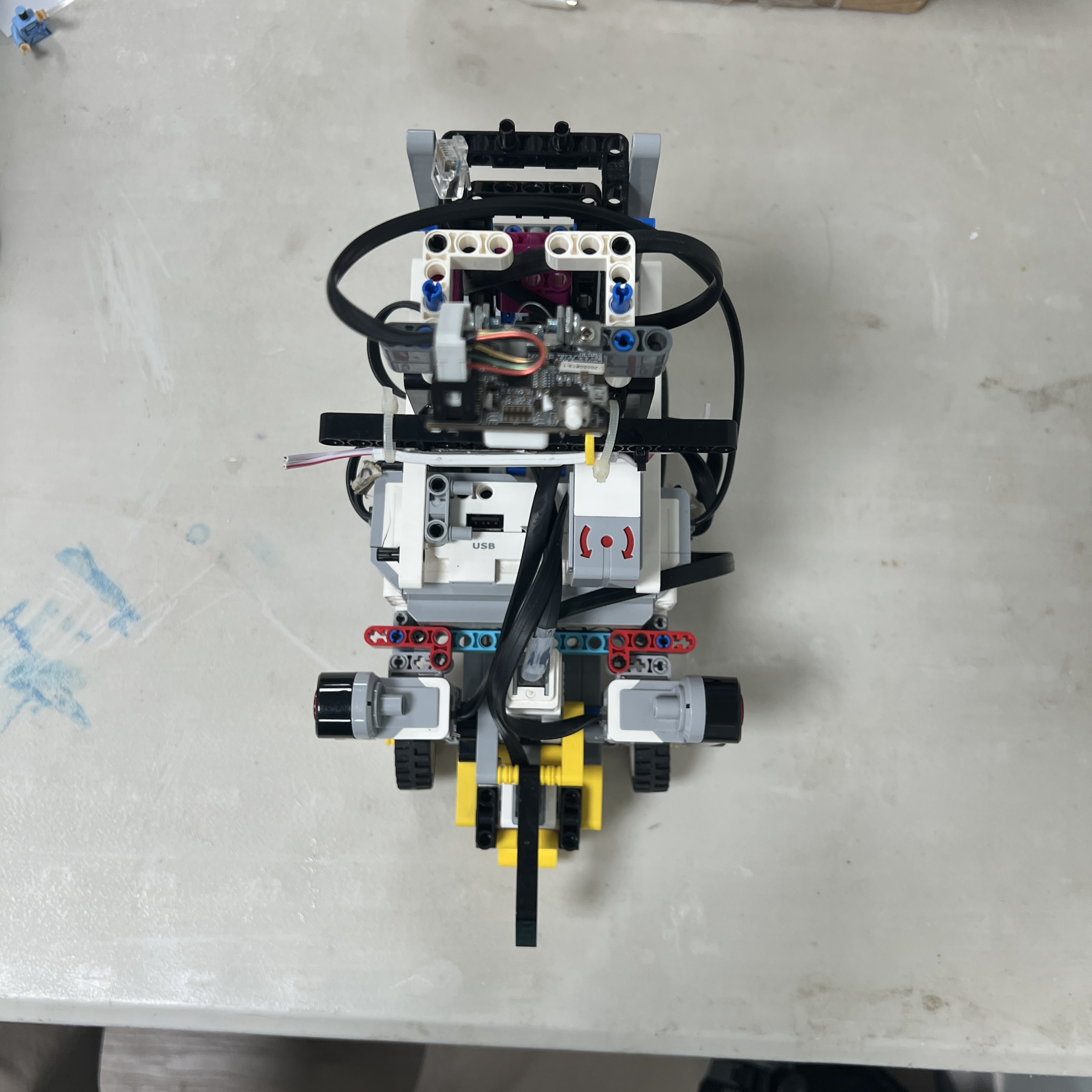 Figure 4.16. Open configuration using the same front steering system employed during the Obstacle Challenge.
Piolín does not replace the steering mechanism between rounds.
The following remain unchanged:
```text
Motor B
Motor B mount
Ackermann linkage
front pivots
front wheel geometry
mechanical center
physical steering limits
```
Only the perception system that generates the steering request changes.
```text
OPEN
→ Gyro + ultrasonic geometry + course state
OBSTACLES
→ Pixy2.1 + ultrasonic geometry + course state
```
Maintaining the same steering platform prevents the team from having to mechanically recalibrate two different vehicles.
---
# 4.39 Current vs. Earlier Steering Versions
Piolín's front assembly evolved during development.
Changes to:
```text
structural reinforcement
wheel support
linkage arrangement
motor mounting
```
can change steering behavior even when Motor B remains the same component.
Historical photographs and old steering values therefore should not be treated as the current V4 specification automatically.
The current steering reference is the physical assembly documented in the V4 images in this repository.
---
# 4.40 Values Intentionally Not Claimed as Final
The following quantities should be measured from the current V4 mechanism before being published as final numerical specifications:
```text
Motor B mechanical center value
maximum useful Motor B left position
maximum useful Motor B right position
left wheel angle at each steering position
right wheel angle at each steering position
steering linkage ratio
measured backlash
center repeatability
left/right steering symmetry
steering response time
minimum turning radius
left/right turning-radius difference
final Open steering limits
final Obstacle steering limits
```
The steering architecture can be documented accurately without inventing these numbers.
---
# 4.41 Recommended Steering Characterization
A complete quantitative steering characterization can be performed with the current V4 robot.
### Motor-to-wheel calibration
Record several Motor B positions and physically measure:
```text
left wheel angle
right wheel angle
```
This establishes the relationship between actuator command and actual steering geometry.
### Center repeatability
Repeatedly move:
```text
LEFT
→ CENTER
→ RIGHT
→ CENTER
```
and measure whether the wheels return to the same orientation.
### Left-right comparison
Apply equal-magnitude commands on both sides and compare:
```text
wheel angles
turning behavior
```
### Dynamic steering test
Measure the physical response while Motor A is driving at a controlled speed.
This reveals behavior that cannot be observed while the front wheels are unloaded.
### Turning-radius test
Use a fixed steering position and controlled propulsion command, then measure the resulting physical path.
All measurements should be taken from the present V4 vehicle.
---
# 4.42 Steering as a Feedback System
The steering mechanism does not only respond to sensors. It also changes what the sensors observe.
The complete loop is:
```text
SENSORS
↓
EV3
↓
Motor B
↓
front-wheel angle
↓
vehicle trajectory changes
↓
vehicle position / heading changes
↓
sensor geometry changes
↓
SENSORS
```
During Open:
```text
steering
→ changes gyro heading
→ changes S2/S3 wall geometry
```
During Obstacles:
```text
steering
→ changes Pixy viewpoint
→ changes S2/S3 wall geometry
```
The steering system therefore sits directly between Piolín's perception and its next sensor observation.
---
# 4.43 Complete Steering Chain
The complete current system can be summarized as:
```text
EV3
│
▼
MOTOR B
│
▼
MOTOR MOUNT
│
▼
STEERING LINKAGE
/ \
▼ ▼
LEFT PIVOT RIGHT PIVOT
│ │
▼ ▼
LEFT WHEEL RIGHT WHEEL
\ /
\ /
▼ ▼
VEHICLE CURVATURE
│
▼
NEW VEHICLE STATE
│
▼
SENSOR FEEDBACK
│
└──────→ EV3
```
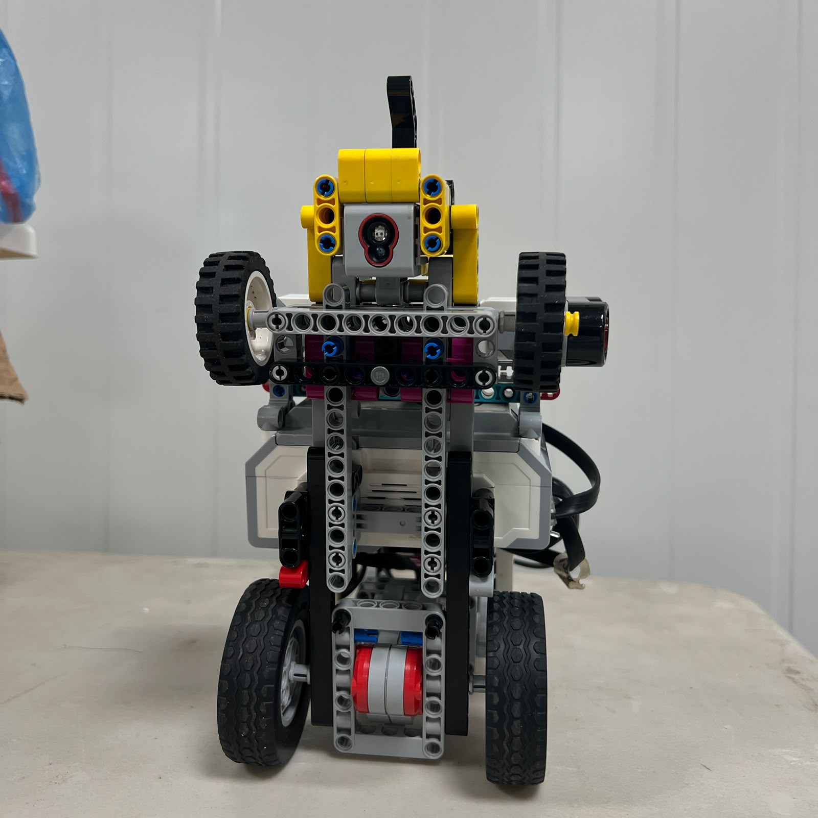 Figure 4.17. Bottom view of the current vehicle showing how the front steering assembly integrates with the rest of the chassis.
This chain illustrates why steering cannot be evaluated using only Motor B encoder values.
The final trajectory also depends on:
```text
linkage geometry
mechanical center
front-wheel angles
vehicle speed
traction
mechanical play
sensor feedback
```
---
# 4.44 Final Engineering Assessment
Piolín's steering architecture combines an EV3 Medium Motor with an Ackermann-style front linkage to create a dedicated vehicle-direction system independent from propulsion.
The design allows the same mechanical assembly to perform:
```text
straight-line corrections
clockwise corners
counterclockwise corners
red-pillar avoidance
green-pillar avoidance
countersteering
post-obstacle recovery
parking
```
without changing the steering hardware between competition rounds.
The most important engineering distinction is:
> **The EV3 controls Motor B, but the track trajectory is determined by the complete mechanical system between Motor B and the front wheels.**
Motor position, linkage geometry, wheel angles, mechanical play, structural rigidity, vehicle speed, and tire interaction all contribute to the final result.
For this reason, steering problems should not automatically be treated as software problems, and software tuning should not begin until the mechanical center, movement range, pivots, linkage, and Motor B mounting are verified.
Piolín's design intentionally keeps the actuator architecture simple:
```text
Motor A
→ propulsion
Motor B
→ steering
```
while using mechanical geometry to create the required vehicle behavior.
The final steering philosophy can therefore be summarized as:
> **Use a mechanically repeatable Ackermann-style system to transform one controlled steering actuator into predictable vehicle curvature, then use sensor feedback to determine when and how strongly that mechanical capability should be applied.**
---
### [← Back to PiolínTech Main README](../../README.md)