# 5. Drivetrain
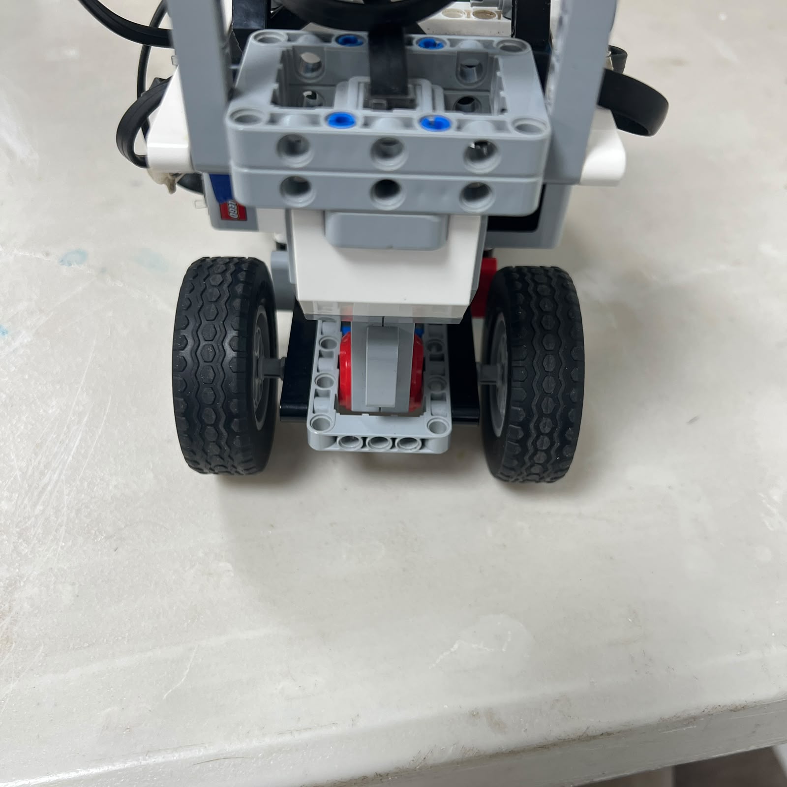 Figure 5.1. Current V4 rear drivetrain transferring Motor A rotation to Piolín's driven rear wheels.
Piolín uses a **rear-wheel propulsion drivetrain** powered by one LEGO Mindstorms EV3 Large Motor connected to **Motor Port A**. The drivetrain is responsible for converting Motor A rotation into longitudinal movement of the robot while the separate front steering system controls the direction of travel.
The drivetrain architecture is intentionally simple:
```text
EV3
↓
Motor A
↓
rear drivetrain
↓
rear wheels
↓
track surface
↓
vehicle movement
```
This arrangement separates the two main vehicle functions:
```text
Motor A
→ propulsion
Motor B
→ steering
```
The drivetrain therefore does not determine whether Piolín turns left or right. Its main responsibility is to provide controlled forward and reverse motion while the Ackermann-style front system establishes vehicle curvature.
The same drivetrain is used during both the Open and Obstacle Challenges.
---
## 5.1 Motor A as the Propulsion Source
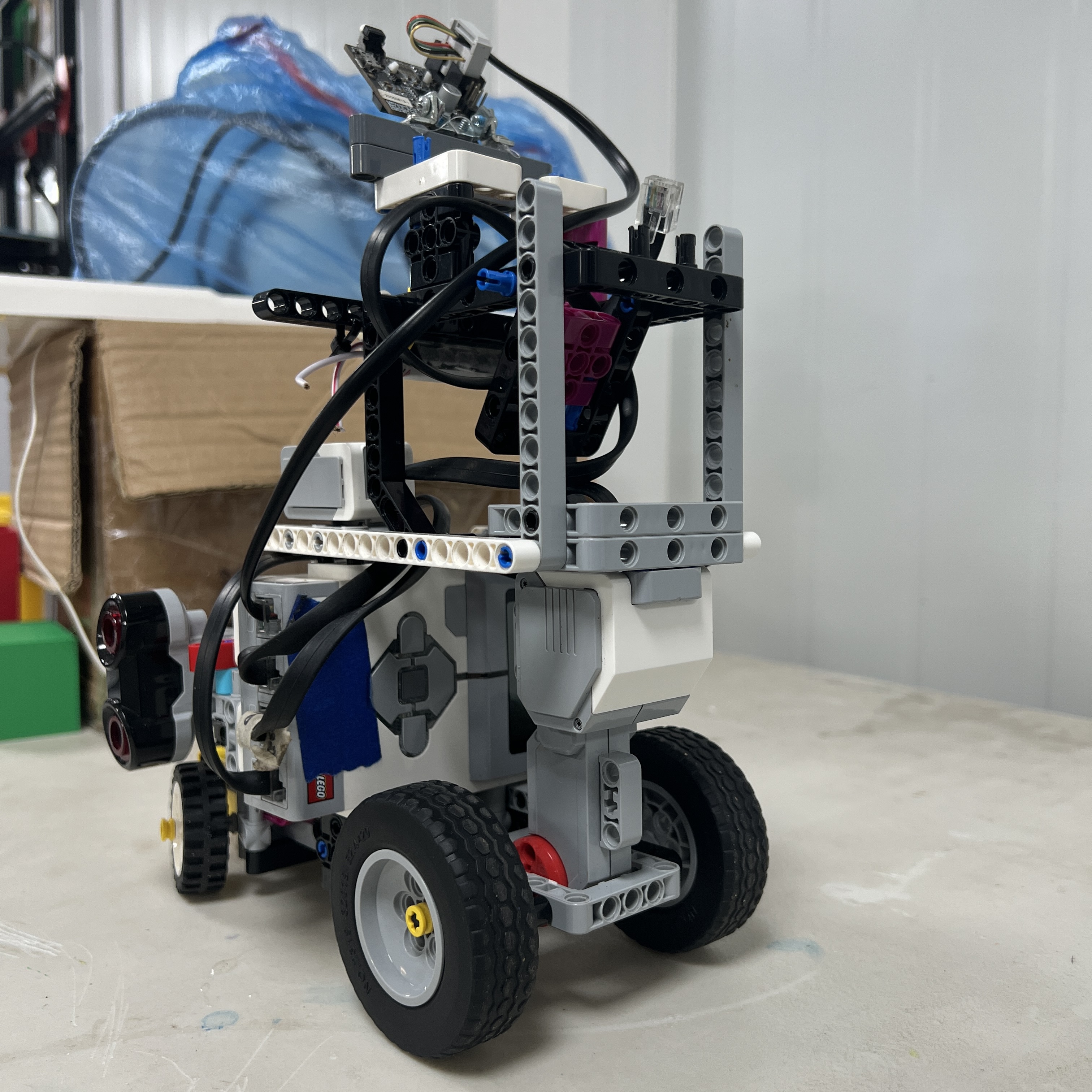 Figure 5.2. EV3 Large Motor on Port A serves as the only propulsion actuator in the current vehicle.
Motor A provides the rotational input to the complete rear propulsion system.
Its role can be summarized as:
```text
electrical command
↓
motor torque and rotation
↓
mechanical transmission
↓
rear-wheel rotation
↓
vehicle displacement
```
Piolín does not use separate left and right propulsion motors.
Instead, one dedicated drive motor supplies the rear drivetrain while Motor B independently controls steering.
This keeps the actuator architecture compact and avoids requiring synchronization between multiple propulsion motors.
---
## 5.2 Why a Large Motor Was Used for Drive
The propulsion motor must move the mass of the complete vehicle and overcome several forms of mechanical resistance.
These include:
```text
rolling resistance
drivetrain friction
wheel deformation
cornering resistance
acceleration load
```
The EV3 Large Motor is used because propulsion requires sustained rotational output rather than the shorter angular positioning movements required from the Medium Motor used for steering.
The two motors therefore perform complementary roles:
```text
Large Motor A
→ sustained vehicle movement
Medium Motor B
→ steering positioning
```
Using different actuator roles allows the mechanical architecture to remain simple while still providing independent control over vehicle speed and direction.
---
## 5.3 Motor A Mounting
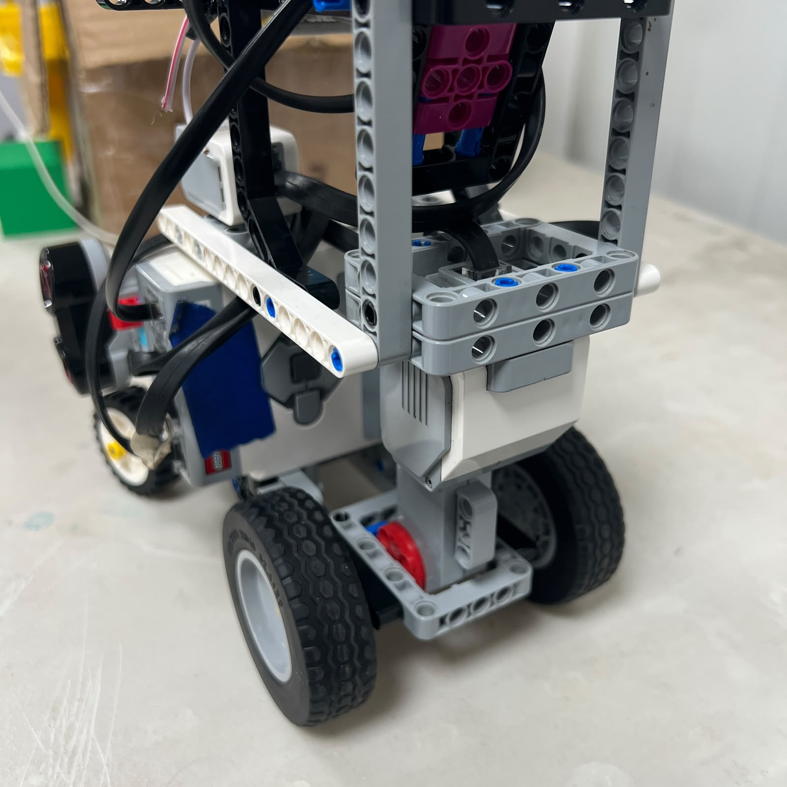 Figure 5.3. Motor A mounting structure establishes the mechanical reference between the propulsion motor and the rear drivetrain.
The motor mount is part of drivetrain performance.
If Motor A shifts relative to the rest of the drivetrain:
```text
alignment changes
↓
friction may increase
↓
rotation transfer becomes less consistent
```
A stable motor mount therefore helps preserve:
```text
axle alignment
gear alignment
drivetrain geometry
repeatable encoder-to-motion behavior
```
This is why a propulsion problem should not immediately be treated as a software-speed problem.
A loose mount or changed structural alignment can produce similar symptoms.
---
## 5.4 Rear Drivetrain Layout
Figure 5.4. Top view of the complete rear propulsion structure.
The drivetrain connects the output of Motor A to the driven rear wheels through LEGO mechanical elements such as:
```text
axles
gears
bushings
connectors
wheel hubs
structural supports
```
depending on the exact current V4 arrangement.
The function of these components is to transmit rotation while keeping the rotating elements properly aligned.
The drivetrain must therefore satisfy two competing requirements:
```text
sufficient structural support
```
and:
```text
low rotational resistance
```
Too little support can create movement and misalignment.
Too much constraint can create friction.
---
## 5.5 Bottom Drivetrain View
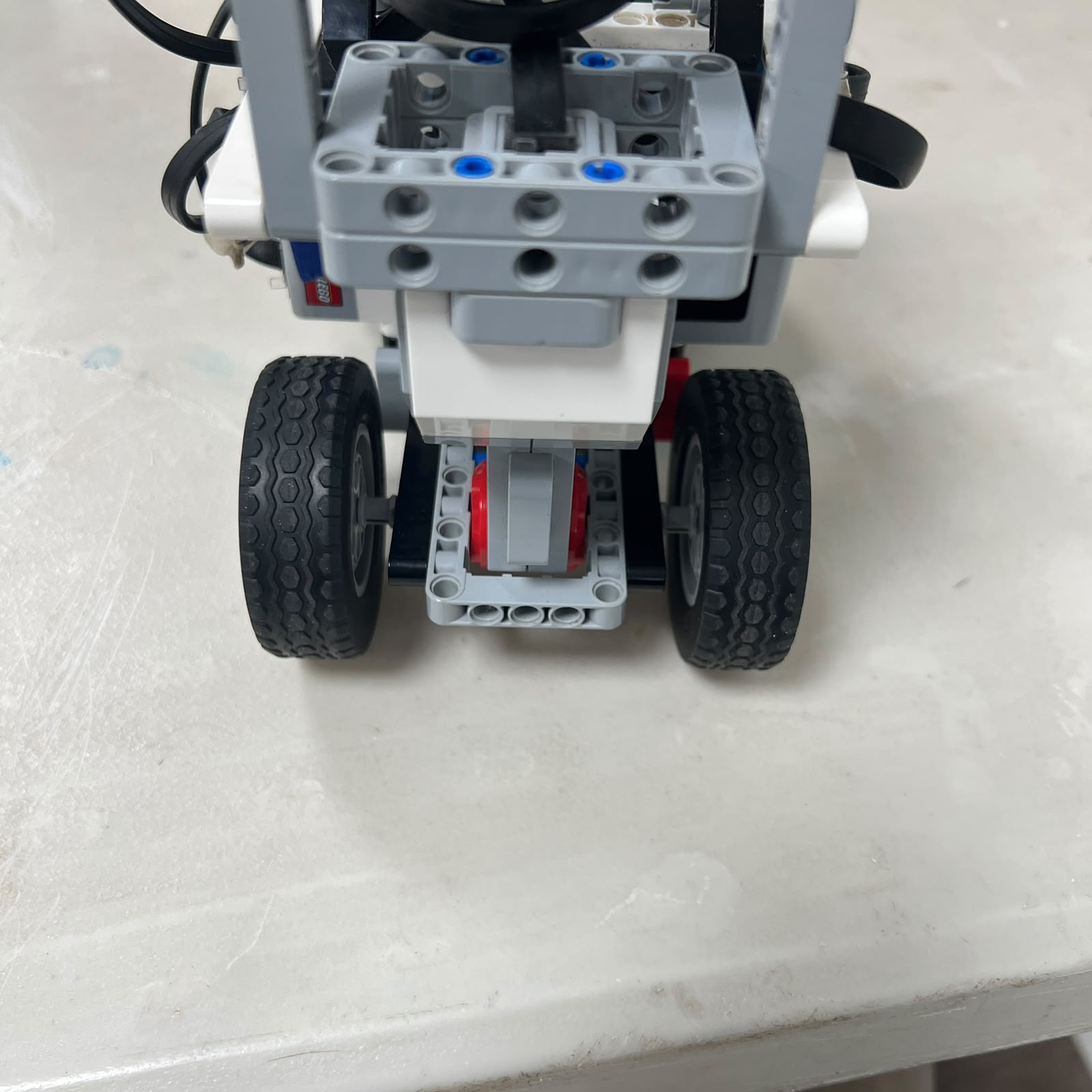 Figure 5.5. Bottom view showing the rear axles, wheel support, and surrounding chassis structure.
The underside provides a useful perspective for identifying:
```text
axle support
wheel clearance
structural interference
alignment
drivetrain symmetry
```
A drivetrain can appear correctly assembled from above while still containing friction or misalignment underneath.
For this reason, mechanical inspection should include both sides of the assembly.
---
## 5.6 Rear-Wheel Drive
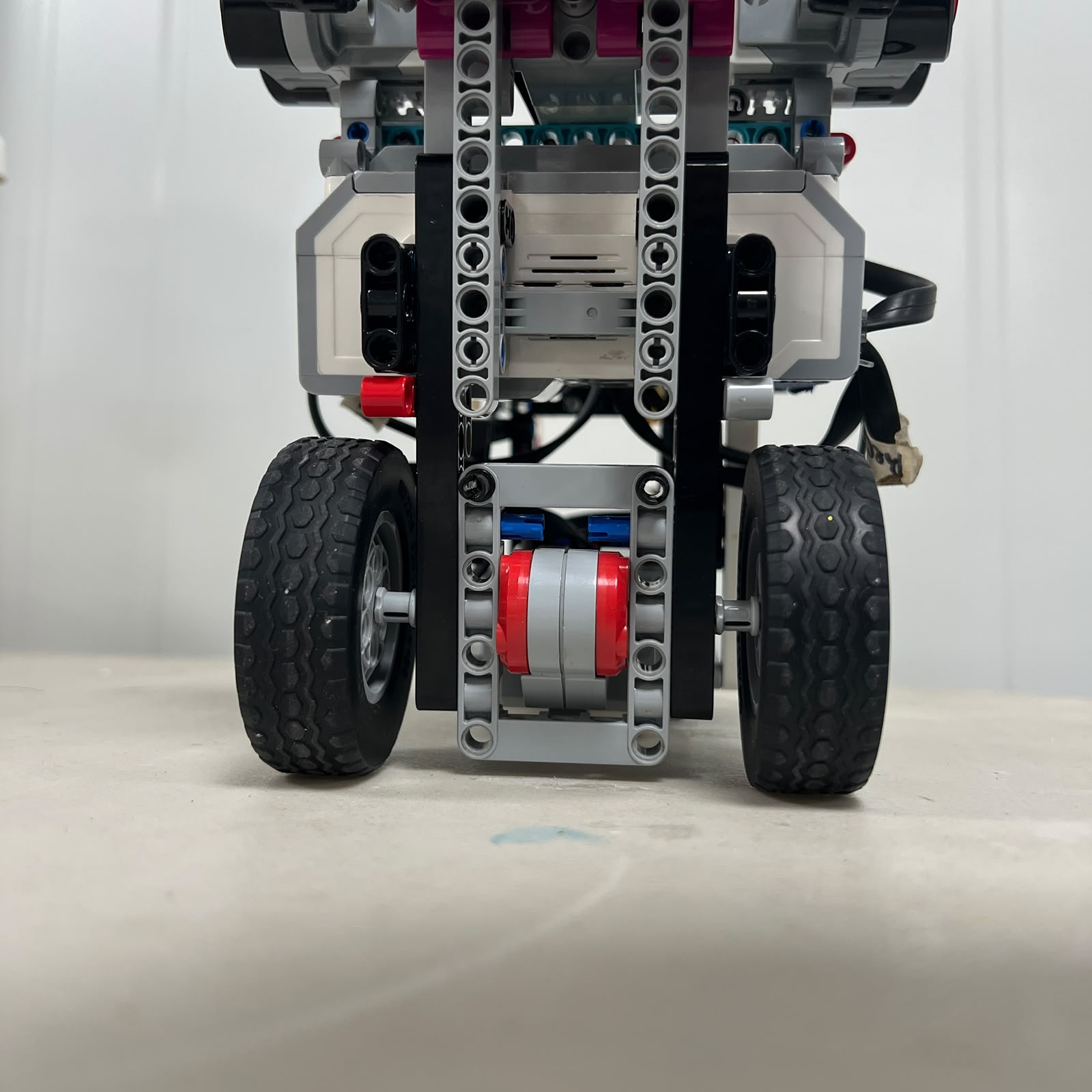 Figure 5.6. Rear wheels transfer drivetrain rotation into longitudinal force against the competition mat.
The rear wheels are the final mechanical stage of the propulsion system.
The intended chain is:
```text
Motor A rotation
↓
drivetrain rotation
↓
rear-wheel rotation
↓
traction force
↓
Piolín moves
```
The rear wheels therefore determine how effectively the motor's rotational output becomes real vehicle displacement.
Their performance depends not only on motor command but also on interaction with the track surface.
---
## 5.7 Traction
A rotating wheel only moves the robot effectively when sufficient traction exists between the tire and the mat.
The ideal assumption is:
```text
wheel rolls
→ robot moves by the same corresponding distance
```
In practice:
```text
wheel slip
tire deformation
surface contamination
cornering load
rapid acceleration
```
can reduce the accuracy of that assumption.
This distinction is important because the drivetrain encoder can report that the motor rotated correctly even if the vehicle did not travel the ideal calculated distance.
Therefore:
```text
encoder rotation
```
and:
```text
physical displacement
```
should be treated as related but not identical quantities.
---
## 5.8 Effective Wheel Diameter
The effective driven-wheel diameter is important when converting encoder rotation into estimated distance.
For an ideal wheel:
```text
circumference = π × D
```
where:
```text
D
= effective wheel diameter
```
One complete wheel revolution would then correspond approximately to:
```text
distance = π × D
```
If the drivetrain contains a transmission ratio between Motor A and the wheel, that ratio must also be considered.
The current V4 wheel diameter should be physically measured before a final numerical conversion factor is published.
Earlier wheel dimensions should not automatically be reused.
---
## 5.9 Encoder-Based Distance
Motor A contains an encoder that provides a rotational reference.
A simple ideal-distance model can be written as:
```text
distance =
wheel revolutions
×
wheel circumference
```
or:
```text
distance =
(θ_wheel / 360°)
×
πD
```
where:
```text
θ_wheel
= wheel rotation in degrees
```
If Motor A rotation differs from wheel rotation because of gearing:
```text
θ_wheel =
θ_motor × transmission factor
```
The exact transmission factor must come from the final physical drivetrain.
This approach can support:
```text
controlled forward movement
reverse movement
parking displacement
relative distance testing
```
but it should not be presented as perfect global odometry.
---
## 5.10 Why Encoder Distance Is an Estimate
Encoder-based distance can contain error even when the motor encoder itself is accurate.
Sources include:
```text
wheel slip
effective tire radius
mechanical backlash
drivetrain play
turning motion
surface variation
```
During a straight section, the relationship between wheel rotation and vehicle displacement is relatively simple.
During a turn, the vehicle follows an arc and the wheels travel different geometric paths.
Therefore an encoder-only distance model becomes less representative of complete vehicle position during strong steering.
---
## 5.11 Transmission Ratio
A gear ratio changes the relationship between:
```text
Motor A rotation
```
and:
```text
rear-wheel rotation
```
A conceptual ratio can be written as:
```text
G =
motor rotation
/
wheel rotation
```
Depending on the mechanical arrangement, gearing can trade:
```text
wheel speed
```
against:
```text
available torque
```
A higher wheel-speed arrangement can increase theoretical travel speed but may reduce mechanical advantage.
A torque-oriented arrangement can provide greater mechanical advantage but reduce wheel rotational speed.
The current V4 ratio should only be documented after directly verifying the gear arrangement installed on Piolín.
---
## 5.12 Speed vs. Torque Trade-Off
The drivetrain cannot maximize every performance characteristic simultaneously.
Conceptually:
```text
more wheel speed
↔
less mechanical advantage
```
while:
```text
more mechanical advantage
↔
less wheel speed
```
The useful choice depends on the requirements of the course.
Piolín needs enough propulsion to complete the course efficiently, but also enough controllability for:
```text
corner entry
obstacle reaction
reverse recovery
parking
```
A drivetrain designed only for maximum speed would make the steering controller's task harder.
The objective is therefore not maximum theoretical velocity but **usable autonomous vehicle performance**.
---
## 5.13 Drivetrain Friction
Internal friction reduces the amount of Motor A output available for vehicle movement.
Possible sources include:
```text
misaligned axle supports
bushings pressed too tightly
gear contact
wheel rubbing
bent structural alignment
axle side-loading
```
A change in drivetrain friction can produce symptoms such as:
```text
slower acceleration
reduced top speed
different reverse displacement
longer run time
```
even though the software has not changed.
This makes drivetrain friction an important controlled variable during software testing.
---
## 5.14 Manual Friction Inspection
One simple mechanical diagnostic is to inspect the drivetrain with the robot powered off.
The rear drivetrain can be checked for:
```text
unexpected resistance
wheel rubbing
gear binding
unequal left/right motion
axle movement
```
The objective is not necessarily to achieve completely resistance-free motion.
Some friction is unavoidable.
The purpose is to detect a significant change from the robot's normal mechanical condition before attempting to compensate in software.
---
## 5.15 Axle Alignment
Axles should remain aligned with their intended rotational path.
If an axle is forced sideways:
```text
friction increases
```
and if its supports are not sufficiently constrained:
```text
mechanical movement increases
```
A well-supported axle therefore needs:
```text
alignment
controlled axial position
freedom to rotate
```
at the same time.
This is another example of the mechanical balance between rigidity and freedom of movement.
---
## 5.16 Bushings and Axial Position
Bushings and axle restraints help prevent drivetrain elements from sliding out of their intended positions.
Without adequate restraint:
```text
gear spacing can change
wheel position can shift
axle alignment can change
```
However, excessive compression can also increase friction.
The goal is:
```text
secure positioning
+
free rotation
```
rather than maximum physical compression.
---
## 5.17 Gear Alignment
Where gears are used, alignment strongly affects drivetrain efficiency.
Poor meshing can cause:
```text
excessive friction
noise
uneven rotation
tooth loading
increased Motor A effort
```
A gear pair should remain engaged sufficiently to transfer rotation without being forced tightly against each other.
Changes to nearby chassis elements should therefore be followed by a drivetrain inspection.
A structural modification can unintentionally alter gear alignment.
---
## 5.18 Mechanical Backlash
Clearance between gears, axles, and connections can create drivetrain backlash.
This effect becomes more visible when Motor A changes direction.
For example:
```text
forward rotation
↓
reverse command
↓
motor reverses
↓
mechanical clearance is taken up
↓
rear wheels begin reversing
```
The software command changes immediately, but the physical direction change can have a short mechanical delay.
This is important for precise:
```text
reverse movement
parking
small recovery maneuvers
```
where the commanded displacement may be relatively short.
---
## 5.19 Forward Motion
Most of Piolín's autonomous course is completed in forward motion.
During a stable straight:
```text
Motor A
→ provides propulsion
Motor B
→ remains close to center with corrections
```
Motor A speed should provide enough forward progress while leaving the steering system enough time to react to sensor information.
Increasing speed also increases the distance Piolín travels during:
```text
sensor processing
steering response
corner detection
obstacle reaction
```
Therefore Motor A speed is not simply a performance setting.
It directly affects navigation geometry.
---
## 5.20 Reverse Motion
Motor A can also be commanded in the opposite rotational direction.
This allows Piolín to move backward for:
```text
repositioning
recovery
obstacle maneuver support
parking
```
A reverse maneuver can be defined using:
```text
time
```
or:
```text
encoder displacement
```
A timed reverse is easy to implement but depends more heavily on practical motor speed.
An encoder-defined reverse provides a rotational reference but still remains affected by:
```text
traction
backlash
wheel geometry
```
The appropriate method depends on how precise the physical maneuver must be.
---
## 5.21 Direction Reversal
Changing directly from forward to reverse places different demands on the drivetrain than steady-state motion.
The physical sequence is approximately:
```text
forward vehicle movement
↓
Motor A slows
↓
rotation reaches zero
↓
Motor A reverses
↓
drivetrain backlash changes side
↓
rear wheels reverse
↓
vehicle begins moving backward
```
The vehicle therefore does not reverse instantaneously at the exact moment the software command changes.
This should be considered when short recovery maneuvers are calibrated.
---
## 5.22 Drivetrain and Steering Interaction
Although the drivetrain does not mechanically steer Piolín, propulsion strongly affects the result of every steering command.
The same front-wheel angle combined with different Motor A speeds produces different physical behavior.
At low speed:
```text
steering has more time
to alter trajectory
over a short distance
```
At high speed:
```text
Piolín travels farther
before the same steering response develops
```
The drivetrain and steering system must therefore be tuned together.
---
## 5.23 Drivetrain During Open Challenge
During Open, Motor A provides relatively continuous propulsion while the steering controller responds to:
```text
gyro orientation
left/right ultrasonic geometry
floor-state information
```
The drivetrain itself does not change according to clockwise or counterclockwise direction.
Only the steering and sensor interpretation changes.
The propulsion path remains:
```text
Motor A
→ rear drivetrain
→ rear wheels
```
throughout the complete three-lap run.
---
## 5.24 Cornering Load
A vehicle experiences different resistance during a turn than during a straight.
When the front wheels are strongly steered:
```text
tire scrub can increase
rolling resistance can change
vehicle load shifts dynamically
```
Motor A must continue producing enough propulsion for the robot to complete the corner without stalling or becoming excessively slow.
This is one reason a motor command that seems adequate during a straight should also be tested during representative corners.
---
## 5.25 Drivetrain During Obstacle Challenge
The same drivetrain is retained during Obstacles.
The major difference is that Motor B may make faster or stronger steering changes in response to pillars.
Motor A continues propelling the robot while:
```text
Pixy detects target
EV3 selects maneuver
Motor B steers
Piolín moves around pillar
```
The propulsion speed therefore affects the amount of reaction time available to the obstacle controller.
A faster drivetrain setting can make an otherwise correct visual reaction occur too late in physical space.
---
## 5.26 Obstacle Reaction Distance
Consider the sequence:
```text
pillar becomes relevant
↓
Pixy detects
↓
EV3 processes target
↓
Motor B begins steering
↓
vehicle trajectory changes
```
Motor A continues moving Piolín throughout much of this sequence.
Therefore:
```text
higher vehicle speed
→ greater distance traveled before avoidance develops
```
This is why obstacle performance cannot be tuned by camera thresholds or steering alone.
Propulsion speed forms part of the obstacle trajectory.
---
## 5.27 Drivetrain and Countersteering
During post-pillar recovery, Motor A continues providing longitudinal motion while Motor B countersteers.
The resulting path depends on both:
```text
how strongly Motor B reverses steering
```
and:
```text
how far Motor A moves the robot during that time
```
If propulsion is too high for the calibrated recovery timing:
```text
Piolín may travel too far laterally
before the heading is recovered
```
If it is too low:
```text
the maneuver may become unnecessarily slow
```
Again, the drivetrain and steering must be treated as a combined vehicle-control system.
---
## 5.28 Parking and Drivetrain Precision
Parking places greater emphasis on controlled displacement.
The final vehicle position can depend on:
```text
approach speed
forward movement
reverse movement
encoder reference
traction
steering angle
final stop timing
```
A purely timed propulsion command assumes that vehicle speed remains sufficiently constant.
An encoder-based movement uses a better internal reference but still cannot completely eliminate slip or mechanical variation.
The final parking solution should therefore combine drivetrain information with the relevant environmental and course-state sensors rather than relying on Motor A timing alone.
---
## 5.29 Stopping Behavior
Stopping also involves mechanical dynamics.
When Motor A is commanded to stop:
```text
motor command changes
↓
wheel torque changes
↓
vehicle decelerates
↓
vehicle reaches rest
```
The vehicle does not necessarily stop at the exact physical point where the software issued the command.
The final stopping distance can depend on:
```text
vehicle speed
motor control mode
traction
vehicle mass
track surface
```
This is especially relevant near:
```text
parking target
walls
obstacles
```
where positional margin is smaller.
---
## 5.30 Rear Chassis Integration
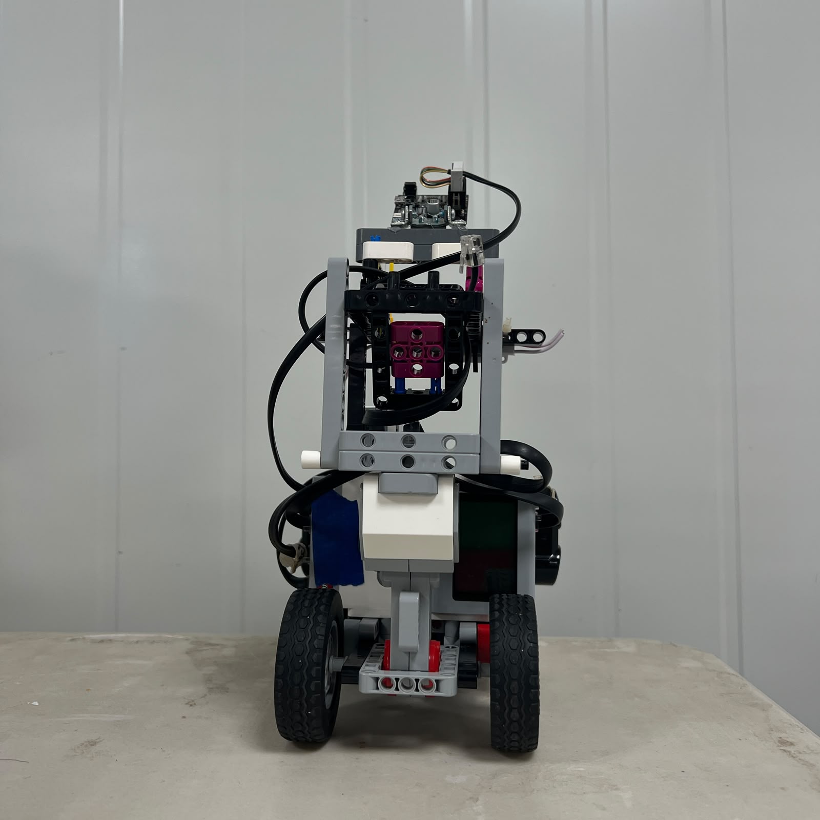 Figure 5.7. Rear chassis structure supporting the propulsion drivetrain and driven-wheel assembly.
The drivetrain cannot be treated independently from the surrounding chassis.
The rear structure must preserve:
```text
Motor A position
axle position
wheel alignment
drivetrain geometry
```
while also resisting the forces generated during acceleration and turning.
If the structure moves under load, drivetrain alignment can change dynamically.
This can reduce repeatability even if the robot appears mechanically correct while stationary.
---
## 5.31 Bottom Vehicle Integration
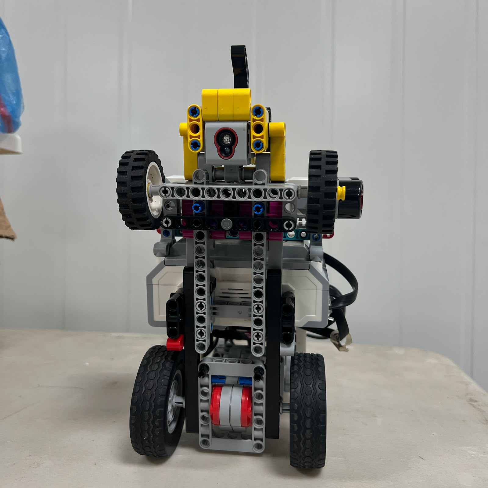 Figure 5.8. Bottom view showing how the rear drivetrain is integrated into the complete vehicle chassis.
This view demonstrates that the drivetrain shares the same physical platform with:
```text
steering structure
Color Sensor
wheel supports
main chassis
```
A mechanical change to one subsystem can therefore indirectly affect another.
For example, reinforcing the chassis can alter axle support geometry if the connection points change.
Mechanical revisions should therefore be followed by another drivetrain inspection.
---
## 5.32 Drivetrain and Vehicle Alignment
A drivetrain can influence straight-line behavior even though steering is handled at the front.
Possible causes of propulsion-induced drift include:
```text
rear axle not perpendicular to vehicle centerline
unequal wheel condition
wheel rubbing on one side
structural misalignment
```
If Piolín consistently drifts while the front wheels are correctly centered, the rear drivetrain should also be inspected before software correction is increased.
Straight-line behavior depends on the complete vehicle geometry.
---
## 5.33 Drivetrain and Battery Condition
The drivetrain converts electrical motor output into physical movement.
If battery condition changes, practical motor response may also change.
Likewise, a mechanically inefficient drivetrain can create symptoms similar to reduced available electrical output.
For example:
```text
Piolín becomes slower
```
could result from:
```text
battery condition
drivetrain friction
wheel rubbing
software motor command
```
The cause should be identified before changing navigation values.
---
## 5.34 Why Maximum Motor Command Is Not Always Better
A higher Motor A command can increase vehicle speed, but autonomous performance does not necessarily improve.
Greater speed reduces the distance margin available for:
```text
corner detection
steering movement
visual obstacle reaction
countersteering
parking
```
It can also increase:
```text
wheel slip
cornering load
mechanical stress
```
The useful propulsion setting is therefore the fastest condition that remains sufficiently controllable and repeatable for the active challenge.
This may differ between Open and Obstacles.
---
## 5.35 Mechanical Efficiency vs. Software Compensation
If Piolín becomes slower because the drivetrain develops excessive friction, one possible response is to increase Motor A power.
That may temporarily restore speed.
However, it does not solve the mechanical cause.
The preferred engineering process is:
```text
detect performance change
↓
inspect mechanical drivetrain
↓
correct friction / alignment problem
↓
retest
↓
only then adjust software if required
```
This keeps software tuning tied to a stable physical platform.
---
## 5.36 Drivetrain Failure Modes
| Observed Behavior | Possible Drivetrain Cause |
| :--- | :--- |
| Motor A runs but Piolín barely moves | Gear/axle disconnect, severe friction, wheel issue |
| Vehicle is slower than usual | Friction, battery condition, wheel rubbing |
| Robot jerks during propulsion | Gear engagement, axle movement, control command |
| Reverse begins with a delay | Mechanical backlash or motor transition |
| Encoder distance does not match physical distance | Slip, wheel diameter assumption, transmission ratio |
| Vehicle drifts despite centered steering | Rear alignment or unequal resistance |
| One wheel appears to bind | Axle support, bushing, wheel contact |
| Motor A sounds loaded | Excessive friction or mechanical interference |
| Speed changes after chassis work | Drivetrain alignment may have changed |
| Parking displacement varies | Traction, backlash, encoder model, battery condition |
The purpose of this table is to prevent every motion error from being treated as a control-code problem.
---
## 5.37 Drivetrain Diagnostic Order
A useful drivetrain diagnostic sequence is:
```text
1. Check rear wheels.
2. Check axles.
3. Check bushings and restraints.
4. Check Motor A mount.
5. Inspect gear alignment.
6. Rotate drivetrain manually.
7. Verify no wheel rub.
8. Test Motor A at low power.
9. Observe encoder movement.
10. Test forward and reverse.
11. Only then perform full navigation testing.
```
This sequence moves from simple physical checks toward complete autonomous testing.
---
## 5.38 Pre-Run Drivetrain Inspection
Before an important run, the propulsion system should be inspected for:
```text
Motor A secure
rear wheels secure
axles fully seated
gears aligned
no visible rubbing
free manual rotation
no unexpected structural movement
```
This process is quick but can prevent a mechanical fault from affecting an entire run.
---
## 5.39 Drivetrain Alternatives
Several propulsion architectures could theoretically be used.
| Architecture | Advantage | Limitation for Piolín |
| :--- | :--- | :--- |
| Two independent rear drive motors | Independent left/right propulsion | Requires synchronization and additional actuator |
| Four-wheel drive | Greater driven-wheel traction | More drivetrain complexity |
| Front-wheel drive | Compact alternative layout | Competes spatially with steering mechanism |
| Differential drive | Steering can be produced by wheel speed | Changes complete vehicle architecture |
| **Single Motor A rear drivetrain** | **Simple propulsion path and only one drive actuator** | **Relies on mechanical transmission and front steering for direction** |
Piolín's design keeps propulsion mechanically simple and leaves directional control to the dedicated steering system.
---
## 5.40 Why Two Drive Motors Were Not Required
Using two propulsion motors could provide:
```text
additional drive power
independent left/right control
```
but it would also introduce:
```text
another motor
additional structure
motor synchronization
more electrical demand
different control architecture
```
Piolín already has a dedicated steering mechanism.
Therefore independent left/right propulsion is not required for direction control.
The single-drive architecture allows the second motor to be dedicated entirely to front steering.
---
## 5.41 Why Four-Wheel Drive Was Not Required
Four-wheel drive can improve traction in systems that require high propulsion force or difficult terrain capability.
The WRO Future Engineers course uses a relatively controlled flat surface.
Piolín's primary challenge is not climbing or off-road traction.
It is:
```text
accurate autonomous trajectory control
```
Adding a second driven axle would increase drivetrain complexity without a currently demonstrated navigation requirement.
The rear-wheel-drive configuration was therefore retained.
---
## 5.42 Same Drivetrain in Both Rounds
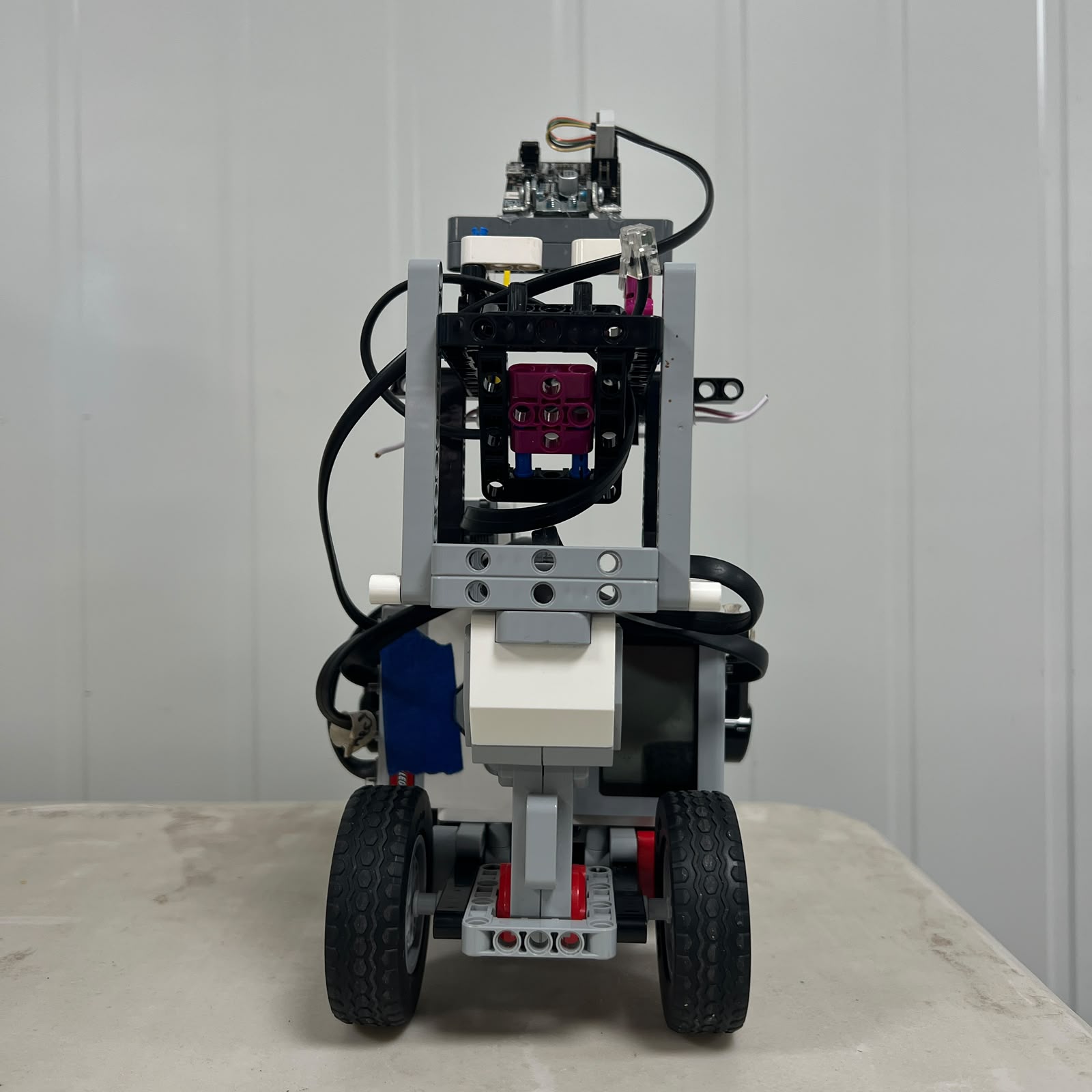 Figure 5.9. Rear propulsion architecture remains unchanged between competition rounds.
The following drivetrain components remain common during both Open and Obstacles:
```text
Motor A
Motor A mount
rear drivetrain
rear axles
rear wheels
chassis support
```
The sensor configuration changes between rounds, but the propulsion architecture does not.
This improves mechanical reproducibility because propulsion calibration does not require rebuilding a second drivetrain.
---
## 5.43 Current vs. Earlier Drivetrain Versions
Piolín's mechanical design has changed through development.
Older configurations may contain:
```text
different wheel arrangement
different chassis geometry
different structural reinforcement
different drivetrain details
```
Those historical versions remain valuable evidence of engineering evolution.
However, current numerical drivetrain specifications should come from the V4 assembly shown in this document.
Old measurements should not be assumed to remain valid.
---
## 5.44 Values Intentionally Not Claimed as Final
The following drivetrain parameters should be physically measured or verified before being published as final values:
```text
rear wheel diameter
effective rear wheel circumference
current drivetrain gear ratio
Motor A-to-wheel rotation ratio
drivetrain mechanical efficiency
maximum validated vehicle speed
maximum useful Motor A command
acceleration
stopping distance
forward encoder scale
reverse encoder scale
measured wheel slip
drivetrain backlash
full robot mass
current draw under propulsion
```
The drivetrain architecture can be documented accurately without fabricating these numbers.
---
## 5.45 Recommended Drivetrain Characterization
A complete V4 drivetrain characterization can be built from several simple experiments.
### Encoder-to-distance test
Command a known Motor A encoder movement and physically measure the resulting straight-line displacement.
Repeat the experiment several times.
This helps estimate:
```text
effective distance per motor degree
```
under real track conditions.
### Forward repeatability test
Use:
```text
same start position
same Motor A command
same encoder target
```
and compare final displacement across several trials.
### Reverse repeatability test
Repeat the same process while moving backward.
This helps identify differences caused by backlash or traction.
### Friction comparison
Compare drivetrain behavior before and after mechanical modifications to identify whether structural changes introduced additional resistance.
### Speed test
Measure physical travel time over a fixed distance for several Motor A commands.
All values should be recorded using the current V4 robot.
---
## 5.46 Full Drivetrain Chain
The complete propulsion system can be summarized as:
```text
EV3 BATTERY
│
▼
EV3
│
▼
MOTOR A
│
▼
MOTOR MOUNT
│
▼
REAR DRIVETRAIN
│
▼
REAR AXLES
│
▼
REAR WHEELS
│
▼
TIRE / TRACK FORCE
│
▼
VEHICLE MOVEMENT
│
▼
NEW SENSOR GEOMETRY
│
└────────→ EV3
```
This demonstrates that propulsion is not an isolated motor function.
Motor A changes vehicle position, and that movement immediately changes what the navigation sensors observe.
The drivetrain therefore forms part of the robot's closed-loop control system.
---
## 5.47 Final Engineering Assessment
Piolín's drivetrain uses a single EV3 Large Motor on Port A to provide rear-wheel propulsion for both WRO Future Engineers challenges.
The design was selected to keep the propulsion system mechanically and electrically simple while allowing the separate front Ackermann steering mechanism to control direction.
The drivetrain consists of more than Motor A alone.
Its behavior depends on:
```text
motor mounting
gear and axle geometry
mechanical friction
rear wheel alignment
traction
effective wheel size
backlash
vehicle speed
battery condition
```
The system supports:
```text
forward movement
reverse movement
Open straight sections
Open corners
Obstacle Challenge approaches
pillar avoidance
countersteering recovery
parking displacement
```
without changing mechanical configuration between rounds.
The most important engineering principle is:
> **A drivetrain should convert motor rotation into repeatable vehicle displacement with as little unnecessary mechanical complexity and resistance as possible.**
For this reason, Piolín's propulsion system is evaluated not only through motor commands but through the complete mechanical chain from Motor A to the competition surface.
The final drivetrain is therefore treated as a **mechatronic subsystem** whose mechanical condition directly affects autonomous navigation accuracy and repeatability.
---
### [← Back to PiolínTech Main README](../../README.md)