# 6. Mobility and Mechanical Testing
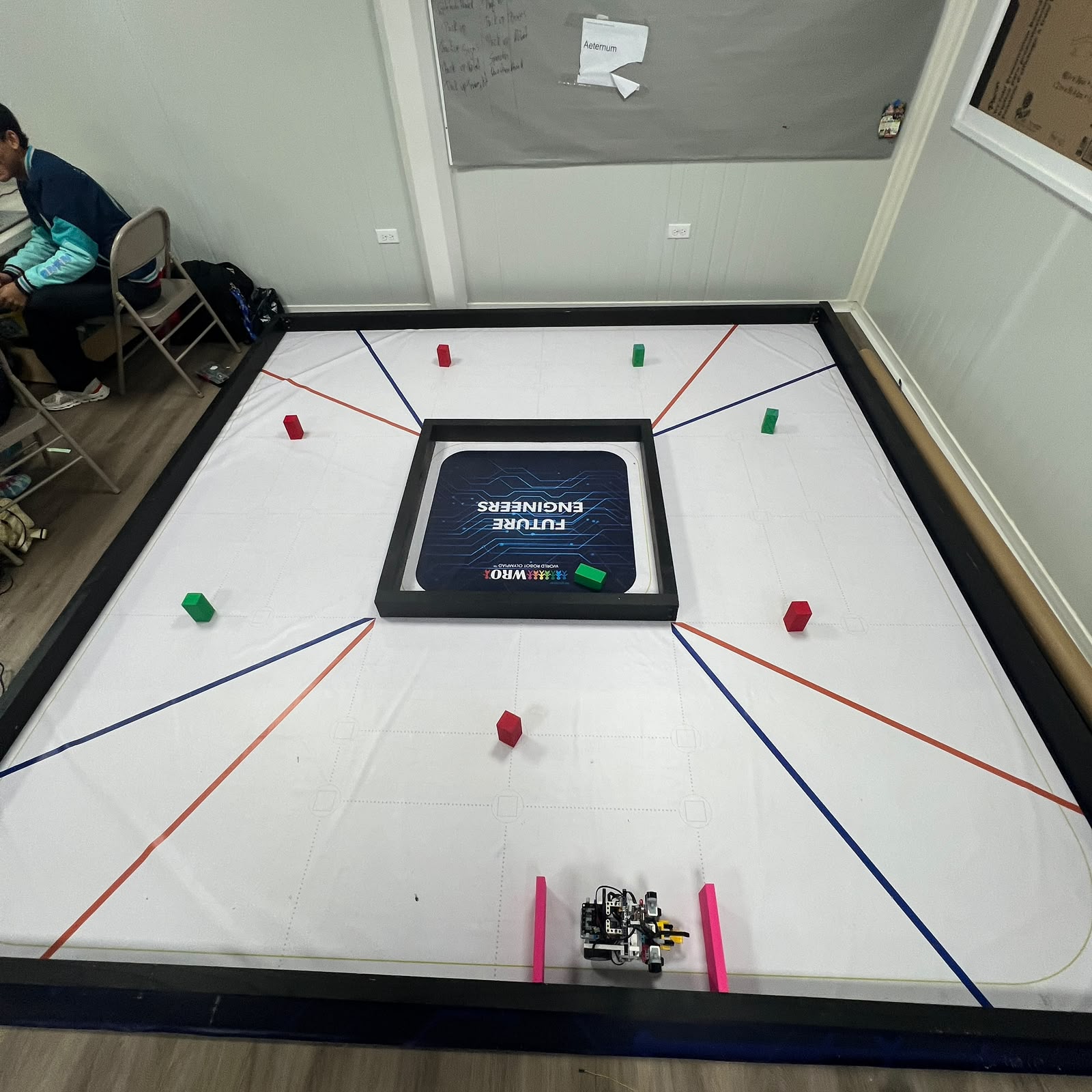 Figure 6.1. Full competition-style track used to evaluate Piolín's mobility system under representative driving conditions.
Piolín's mechanical design is evaluated through repeated physical testing rather than only through visual inspection or theoretical calculations. The purpose of the testing process is to determine whether the drivetrain, steering system, wheels, chassis, and vehicle geometry produce sufficiently repeatable behavior for autonomous navigation.
The main mechanical subsystems tested are:
```text
steering center
steering range
left/right steering behavior
drivetrain freedom
forward movement
reverse movement
straight-line stability
corner execution
obstacle maneuvering
post-obstacle recovery
parking
```
Testing is also used to separate software problems from mechanical problems.
A robot can produce an incorrect trajectory because:
```text
the controller made the wrong decision
```
but it can also fail because:
```text
the mechanical system did not reproduce
the commanded motion correctly
```
For this reason, Piolín's testing process evaluates both the **command** and the **physical response**.
---
## 6.1 Purpose of Mechanical Testing
The objective of mobility testing is not simply to prove that Piolín can move.
A useful autonomous mobility system must be:
```text
repeatable
predictable
mechanically stable
controllable
consistent between runs
```
A drivetrain that works once but changes behavior after several runs is difficult to calibrate.
Likewise, a steering system that reaches a different physical center each time cannot provide a stable reference for wall following, cornering, obstacle avoidance, or parking.
The testing process therefore asks questions such as:
```text
Does Motor B return to the same center?
Do equal left/right commands create similar behavior?
Does the drivetrain travel repeatable distances?
Does reverse motion behave consistently?
Does a corner exit into a useful position?
Does Piolín recover after avoiding a pillar?
Does parking finish in a repeatable area?
```
These questions connect mechanical design directly to autonomous performance.
---
# 6.2 Testing Philosophy
Piolín's testing process follows a simple principle:
> **Change as few variables as possible between two tests.**
If several software and mechanical variables are changed at the same time, it becomes difficult to identify which change caused the observed result.
A useful experimental comparison should therefore try to preserve:
```text
same robot configuration
same starting position
same track
same battery condition
same software version
same sensor arrangement
```
while changing only the variable being investigated.
For example, a steering test should not simultaneously change:
```text
Motor B command
Motor A speed
starting position
steering linkage
```
unless the purpose of the experiment is explicitly to evaluate their interaction.
---
## 6.3 Mechanical Condition Before Testing
Before collecting useful test evidence, Piolín should first be placed in a known mechanical condition.
The inspection sequence includes:
```text
rear wheels secure
drivetrain free
Motor A mount secure
Motor B mount secure
steering linkage connected
front pivots free
steering center checked
ultrasonic mounts stable
Color Sensor mount stable
S1 device correct for the round
```
The reason is straightforward:
```text
unstable hardware
→ unstable experiment
```
A controller cannot be meaningfully compared across trials if the robot itself changes mechanically between them.
---
# 6.4 Test Environment
Figure 6.2. Mechanical tests should progress from isolated subsystem tests to representative full-track runs.
Piolín is tested at several levels.
The first level isolates the subsystem as much as possible:
```text
steering while stationary
manual drivetrain inspection
encoder movement
wheel alignment
```
The second level introduces controlled vehicle motion:
```text
short straight
single steering maneuver
single reverse maneuver
single corner
```
The final level uses the complete track:
```text
multiple corners
three-lap Open behavior
obstacle sequence
recovery
parking
```
This progression helps prevent a full-track failure from hiding the original cause.
---
# 6.5 Test Progression
A useful progression is:
```text
STATIC MECHANICAL TEST
↓
LOW-SPEED MOTION TEST
↓
ISOLATED MANEUVER
↓
REPEATED MANEUVER
↓
MULTI-MANEUVER TEST
↓
FULL RUN
```
Each level adds additional variables.
For example, a full Obstacle Challenge run combines:
```text
camera detection
steering
drivetrain
walls
multiple pillars
corners
recovery
parking
```
If the robot cannot reproduce a simple steering-center test, testing all of those variables together would provide little useful diagnostic information.
---
# 6.6 Steering Center Test
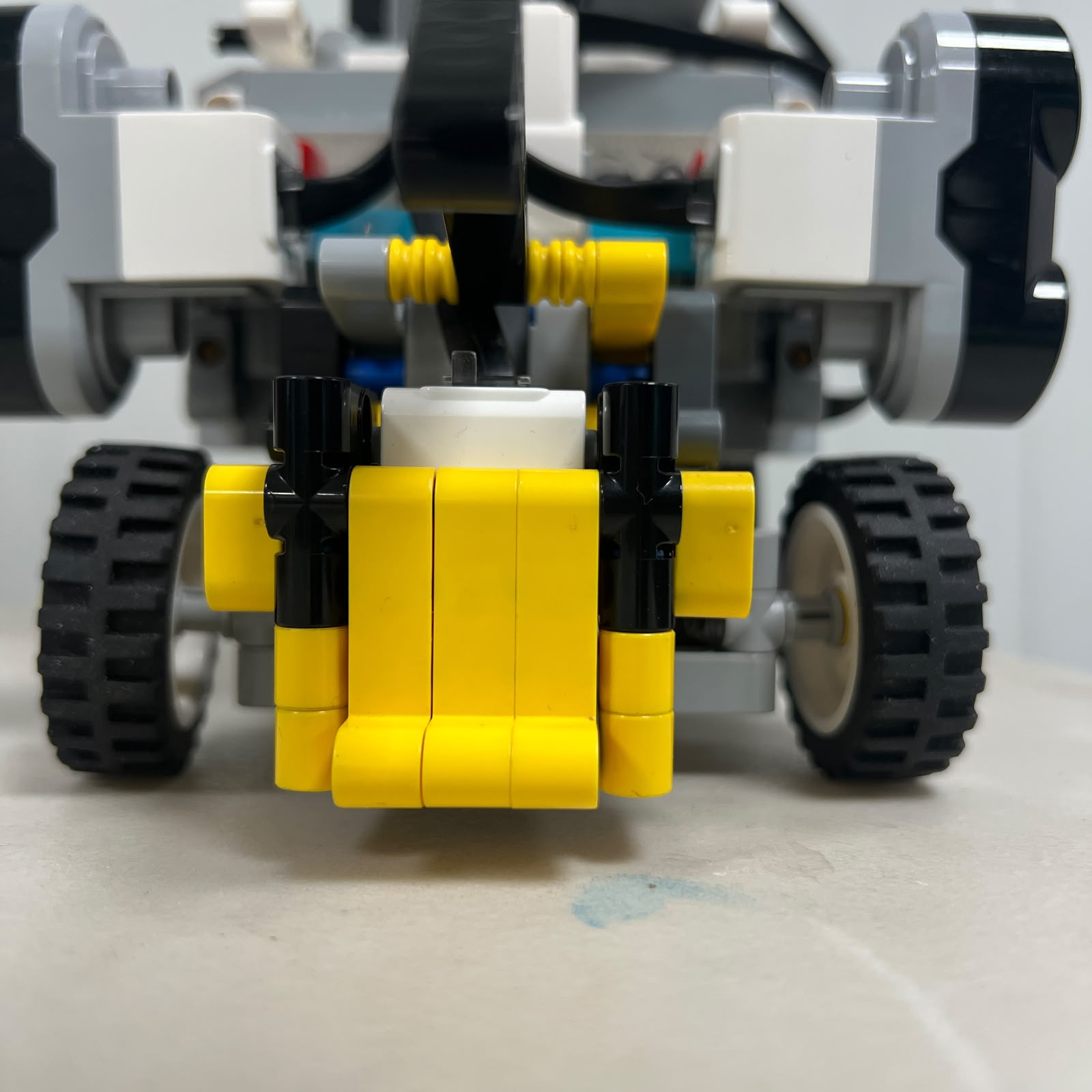 Figure 6.3. Mechanical center is the first reference used during steering testing.
The steering-center test determines whether Motor B can repeatedly return the front wheels to approximately the same neutral orientation.
A test sequence can use:
```text
CENTER
↓
LEFT
↓
CENTER
↓
RIGHT
↓
CENTER
```
and repeat the cycle several times.
The observation should answer:
```text
Do the wheels return to the same visual center?
Does center depend on the direction from which it was approached?
Does Motor B stop at the expected position?
Is there visible linkage play?
```
A different center when approached from the left and right can indicate backlash or mechanical clearance.
---
## 6.7 Why Center Repeatability Matters
Steering center influences every other mobility test.
If center changes:
```text
straight-line behavior changes
```
which then changes:
```text
wall distance
corner approach
obstacle approach
parking alignment
```
Therefore a small center error can propagate into many apparently unrelated failures.
The steering-center test should be repeated after:
```text
front structure changes
Motor B remounting
linkage changes
wheel-support changes
```
before the previous software calibration is reused.
---
# 6.8 Steering Range Test
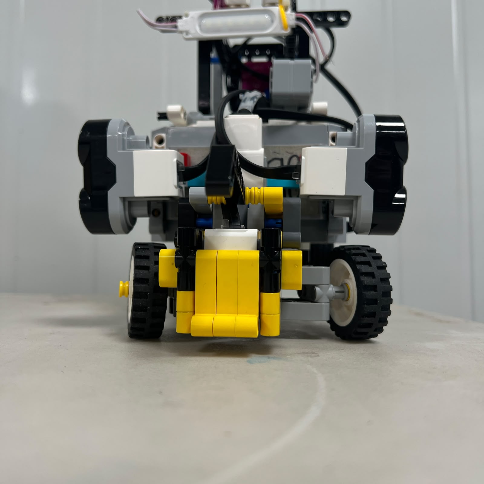 Figure 6.4. Left-side usable steering limit.
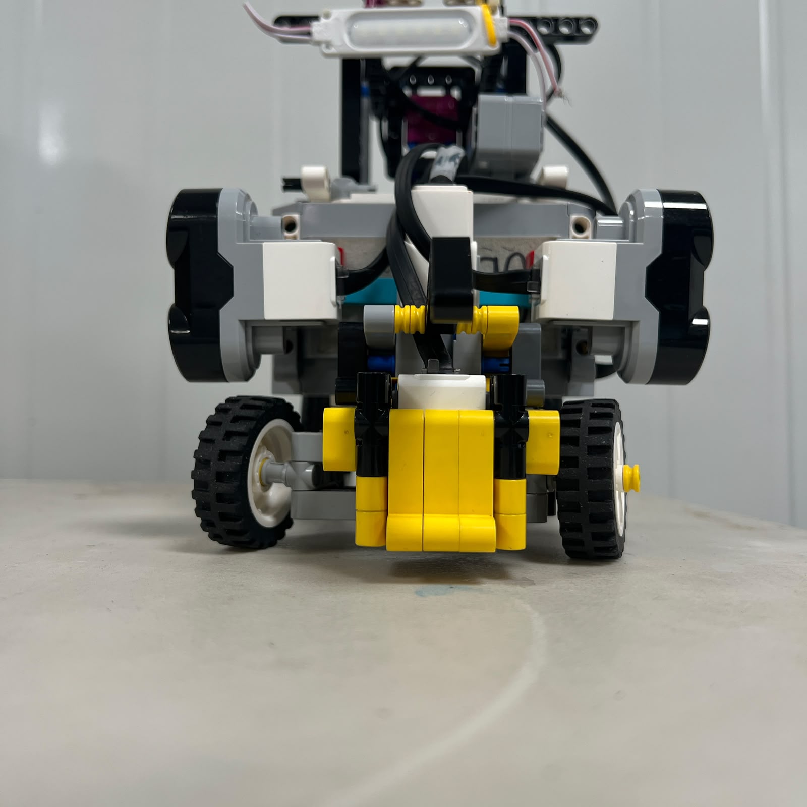 Figure 6.5. Right-side usable steering limit.
The steering-range test identifies the mechanically useful limits of Motor B.
The purpose is not to force the system to its absolute maximum.
Instead, the test identifies the range where:
```text
linkage remains free
wheels move predictably
no structure is contacted
Motor B is not pushing against a hard stop
```
These physical observations establish the safe region within which software steering limits should later be selected.
---
# 6.9 Steering Angle Characterization
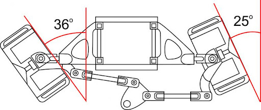 Figure 6.6. Steering-angle reference used to characterize the relationship between Motor B command and physical wheel orientation.
A more detailed test can relate:
```text
Motor B position
```
to:
```text
left wheel angle
right wheel angle
```
A measurement table can use the following format:
| Trial Position | Motor B Reference | Left Wheel Angle | Right Wheel Angle |
| :--- | :---: | :---: | :---: |
| Maximum useful left | — | — | — |
| Intermediate left | — | — | — |
| Center | — | — | — |
| Intermediate right | — | — | — |
| Maximum useful right | — | — | — |
The table should only be populated with measured V4 values.
The purpose is to document that:
```text
motor encoder angle
```
and:
```text
wheel steering angle
```
are different physical quantities.
---
# 6.10 Left/Right Steering Comparison
A steering system should also be tested for practical symmetry.
Equal-magnitude Motor B commands can be applied in opposite directions:
```text
-X
```
and:
```text
+X
```
The physical responses can then be compared.
Relevant observations include:
```text
wheel angle
turning strength
motor effort
response time
mechanical interference
```
The objective is not to force perfect mathematical symmetry.
Instead, the test determines whether the difference between sides is important enough to affect autonomous control.
If a consistent difference exists, software can later treat left and right maneuvers separately.
---
# 6.11 Steering Motion Test
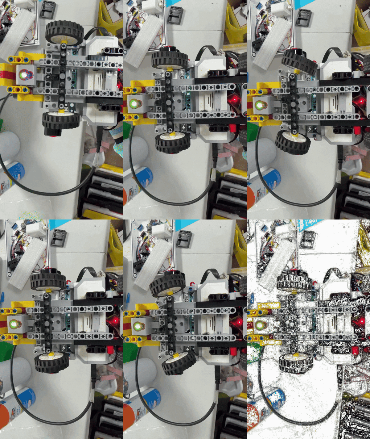 Figure 6.7. Dynamic steering movement used to inspect smoothness, delay, and mechanical play.
Static photographs show the final positions.
The GIF demonstrates the movement between them.
During this test, the team can observe:
```text
smoothness
linkage delay
backlash
left/right response difference
binding
mechanical vibration
```
This matters because autonomous steering consists mainly of **transitions**, not only fixed positions.
Piolín frequently changes between:
```text
straight correction
corner steering
obstacle avoidance
countersteering
recovery
```
The transition quality therefore matters as much as the final steering angle.
---
# 6.12 Straight-Line Test
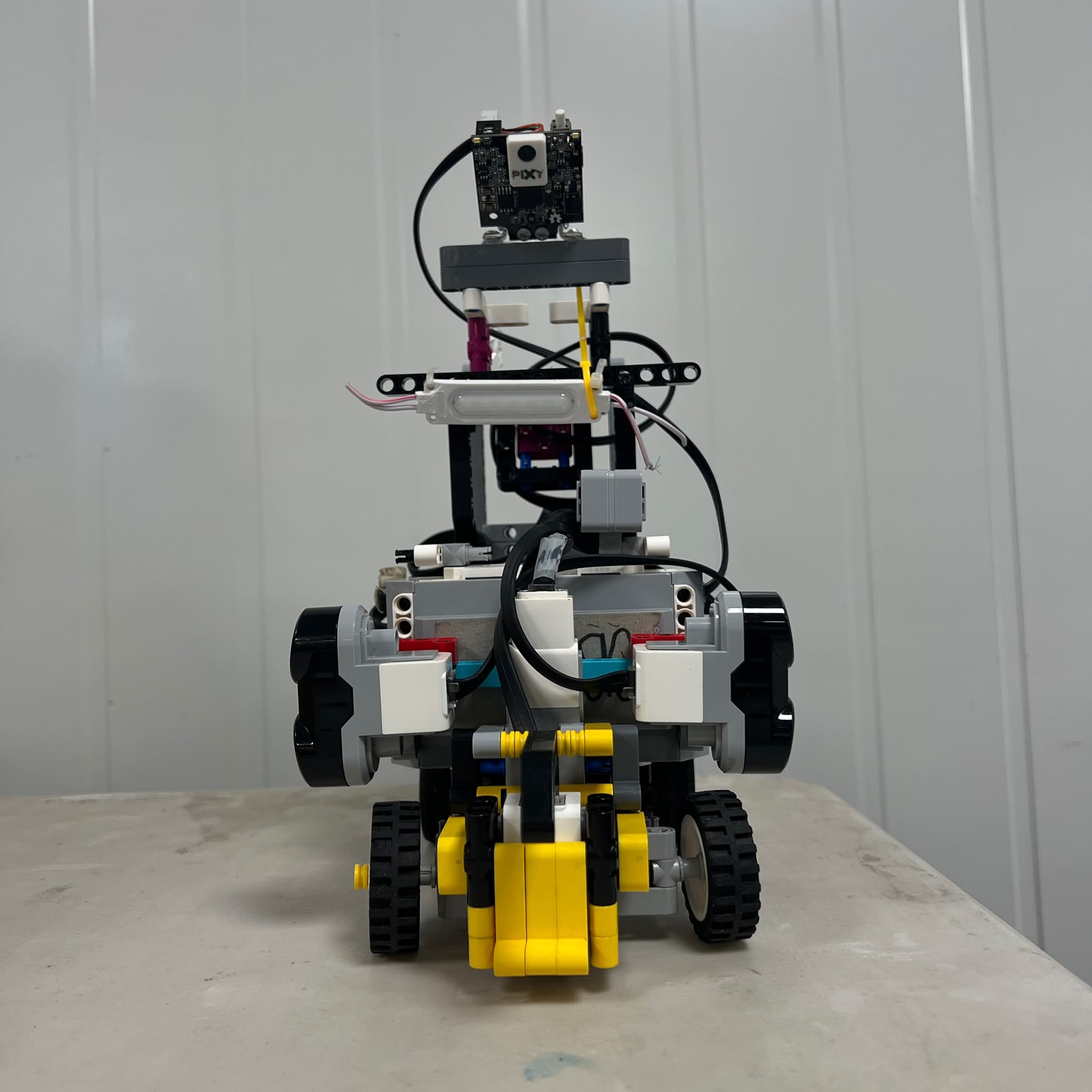 Figure 6.8. Front alignment of the vehicle provides a mechanical reference before straight-line testing.
The straight-line test evaluates the complete relationship between:
```text
steering center
rear-wheel alignment
drivetrain
vehicle structure
```
A basic test should use:
```text
same start position
Motor B at center
same Motor A command
same travel distance
```
and repeat the run several times.
The final position can then be compared.
Useful observations include:
```text
lateral drift direction
final lateral displacement
whether drift is consistent or random
whether the vehicle remains mechanically stable
```
A consistent drift can indicate a fixed bias.
A highly variable drift can indicate mechanical play, sensor influence, surface variation, or inconsistent starting geometry.
---
# 6.13 Mechanical Straight-Line Bias
If Piolín consistently moves toward one side with Motor B physically centered, possible causes include:
```text
front-wheel alignment
rear-axle alignment
unequal wheel resistance
chassis geometry
steering-center offset
```
The appropriate response is not immediately:
```text
increase steering correction
```
The preferred sequence is:
```text
inspect wheels
↓
inspect steering center
↓
inspect drivetrain
↓
repeat straight test
↓
then modify software if necessary
```
This prevents software from compensating for a mechanical fault that may later change.
---
# 6.14 Drivetrain Inspection Test
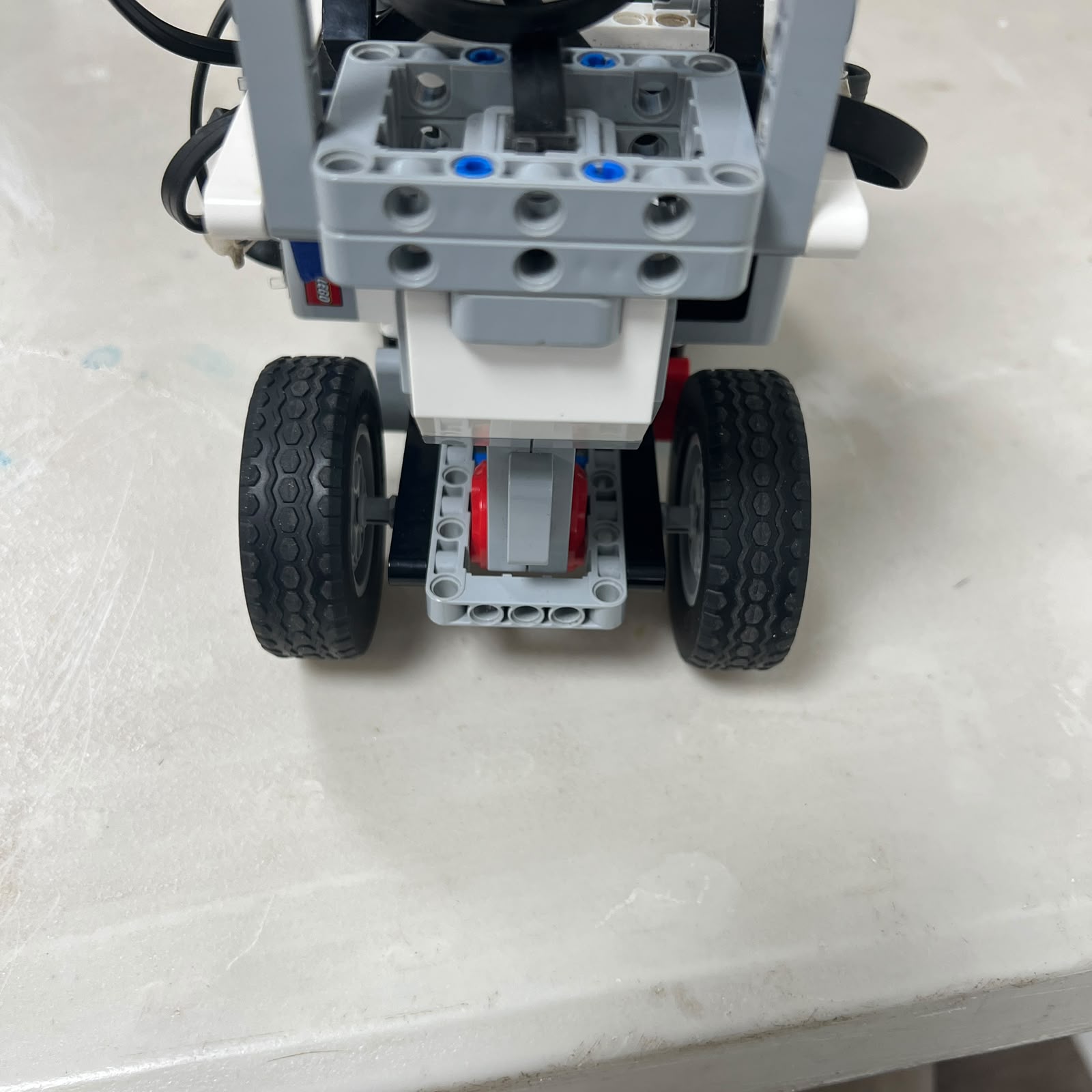 Figure 6.9. Rear drivetrain should be inspected before propulsion tests are interpreted as software results.
The drivetrain test begins with the robot powered off.
The rear-wheel system should be inspected for:
```text
unexpected resistance
wheel rubbing
axle movement
gear binding
structural movement
unequal left/right behavior
```
A change in any of these can alter:
```text
acceleration
vehicle speed
reverse behavior
encoder-distance relationship
```
without any software modification.
---
# 6.15 Rear-Wheel Test
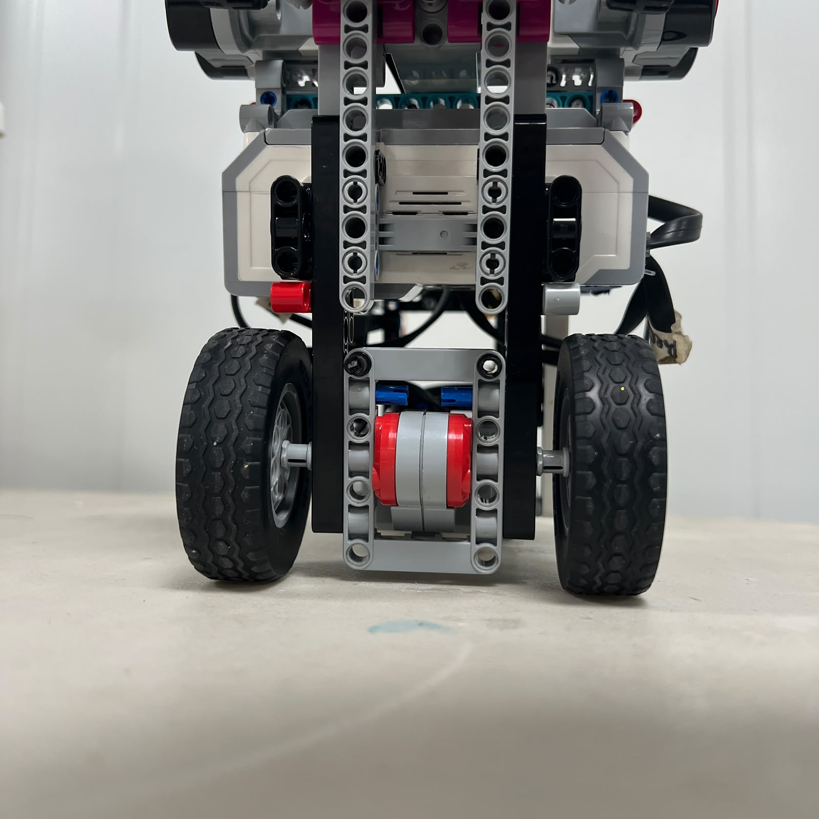 Figure 6.10. Rear-wheel condition and alignment are included in drivetrain testing.
The rear wheels should be inspected for:
```text
secure attachment
free rotation
similar condition
clearance from chassis
axle stability
```
Because Motor A is the only propulsion actuator, drivetrain irregularities directly influence the complete vehicle speed.
A wheel rubbing against the chassis can create a navigation symptom that appears similar to a weak motor or low drive command.
---
# 6.16 Encoder-to-Distance Test
Motor A's encoder can be used as a repeatable rotational reference.
A controlled test can command a fixed encoder displacement:
```text
Motor A rotates N degrees
```
and measure:
```text
actual physical vehicle distance
```
The test should be repeated several times.
A useful table is:
| Trial | Motor A Encoder Movement | Measured Distance | Difference from Mean | Notes |
| :---: | :---: | :---: | :---: | :--- |
| 1 | — | — | — | — |
| 2 | — | — | — | — |
| 3 | — | — | — | — |
| 4 | — | — | — | — |
| 5 | — | — | — | — |
This experiment provides more useful information than relying only on theoretical wheel circumference.
It includes the effect of the actual robot:
```text
wheel geometry
drivetrain
traction
mechanical condition
```
---
# 6.17 Forward Repeatability Test
The encoder test can also be used to evaluate repeatability.
If the same command is given repeatedly:
```text
same Motor A encoder movement
```
Piolín should finish at approximately the same longitudinal position.
The test does not require the displacement to perfectly match the theoretical value.
The important question is:
> **Does the same command produce sufficiently similar physical movement between trials?**
Repeatability is particularly useful for:
```text
parking
short repositioning maneuvers
controlled recovery
```
---
# 6.18 Reverse Repeatability Test
Reverse motion should be tested separately from forward motion.
The sequence can use:
```text
same starting position
same steering position
same reverse encoder command
```
and compare the final positions.
Possible differences between forward and reverse include:
```text
drivetrain backlash
traction
direction-change delay
mechanical play
```
Therefore:
```text
forward distance per encoder degree
```
should not automatically be assumed to be identical to:
```text
reverse distance per encoder degree
```
without testing.
---
# 6.19 Direction-Reversal Test
A useful additional test evaluates the transition:
```text
FORWARD
→ STOP
→ REVERSE
```
and:
```text
REVERSE
→ STOP
→ FORWARD
```
The drivetrain can contain mechanical clearance.
When direction changes:
```text
Motor A reverses
↓
clearance changes side
↓
rear wheels begin responding
```
This creates a small delay before the vehicle moves in the opposite direction.
The effect is particularly relevant to short recovery or parking maneuvers.
---
# 6.20 Turning Test
Turning tests evaluate the drivetrain and steering together.
A controlled turning test should hold:
```text
Motor A command
```
and:
```text
Motor B steering reference
```
approximately constant while the vehicle follows an arc.
The resulting path can be measured to estimate a practical turning radius.
Useful comparisons include:
```text
left vs. right
different steering references
different Motor A speeds
```
The objective is to measure the real vehicle rather than assuming the theoretical Ackermann model perfectly predicts the path.
---
# 6.21 Why Turning Must Be Tested Dynamically
Steering photographs establish geometry while stationary.
They do not capture:
```text
tire deformation
vehicle inertia
traction
drivetrain load
dynamic steering response
```
A physical turning test therefore provides information unavailable from static measurements.
This is especially important because Piolín must execute approximately 90-degree course corners repeatedly during a complete run.
---
# 6.22 Open Challenge Testing
Open testing combines:
```text
drivetrain
steering
S2/S3 geometry
gyro heading
Color Sensor progression
```
The first Open tests should normally focus on:
```text
stable start
straight-line control
single corner
corner exit
```
before attempting the entire three-lap sequence.
A successful single corner should be repeatable from a controlled starting condition before it is assumed to work twelve times consecutively.
---
# 6.23 Corner-Entry Testing
Corner entry can be tested by placing Piolín in the same approach position repeatedly.
The observations should include:
```text
where steering begins
distance to inner wall
distance to outer wall
vehicle heading
entry speed
```
If the turn begins too late:
```text
the path becomes wide
```
If it begins too early:
```text
the path cuts inward
```
Testing should therefore focus not only on whether the robot completes the turn but on **where the turn begins**.
---
# 6.24 Corner-Exit Testing
The exit should also be evaluated independently.
Relevant questions include:
```text
Is Piolín parallel enough to the new straight?
Is it too close to the inner wall?
Is it too close to the outer wall?
Has Motor B returned toward center?
Are the ultrasonic readings usable again?
```
A corner that reaches the correct approximate heading but leaves poor geometry can create a failure several seconds later.
For this reason, the test result should include both:
```text
corner rotation
```
and:
```text
corner exit condition
```
---
# 6.25 Multi-Corner Testing
Once one corner is repeatable, testing can progress to several consecutive corners.
This reveals accumulated errors.
For example:
```text
small exit error
↓
next corner begins from worse position
↓
second error becomes larger
↓
vehicle eventually collides
```
A controller that completes one isolated corner successfully may still fail during a full lap because the state between corners is not sufficiently recovered.
Multi-corner testing therefore evaluates the stability of the complete navigation cycle.
---
# 6.26 Obstacle Challenge Testing
Obstacle testing combines the same mobility platform with visual perception.
The mechanical sequence is:
```text
approach
avoid
pass
countersteer
recover
```
The testing process should determine whether Piolín can complete the full sequence rather than only whether it initially turns away from the pillar.
---
# 6.27 Red Pillar Test
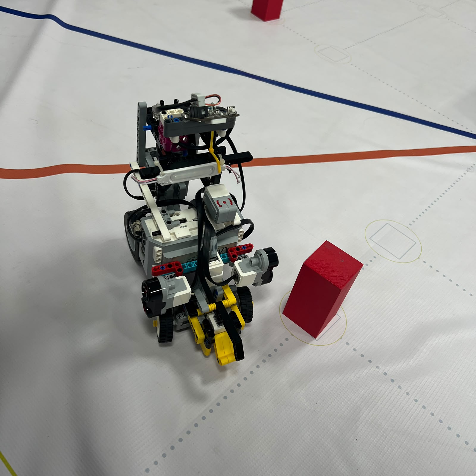 Figure 6.11. Representative red-pillar test used to evaluate the required pass-right trajectory and recovery.
The required rule is:
```text
RED
→ pass RIGHT
```
A red-pillar test should evaluate:
```text
detection
initial steering
clearance from pillar
wall clearance
countersteering
final recovery
```
A successful test should not be defined only as:
```text
Piolín did not hit the red pillar
```
A better result is:
```text
passed correct side
+
maintained acceptable track clearance
+
recovered for next maneuver
```
---
# 6.28 Green Pillar Test
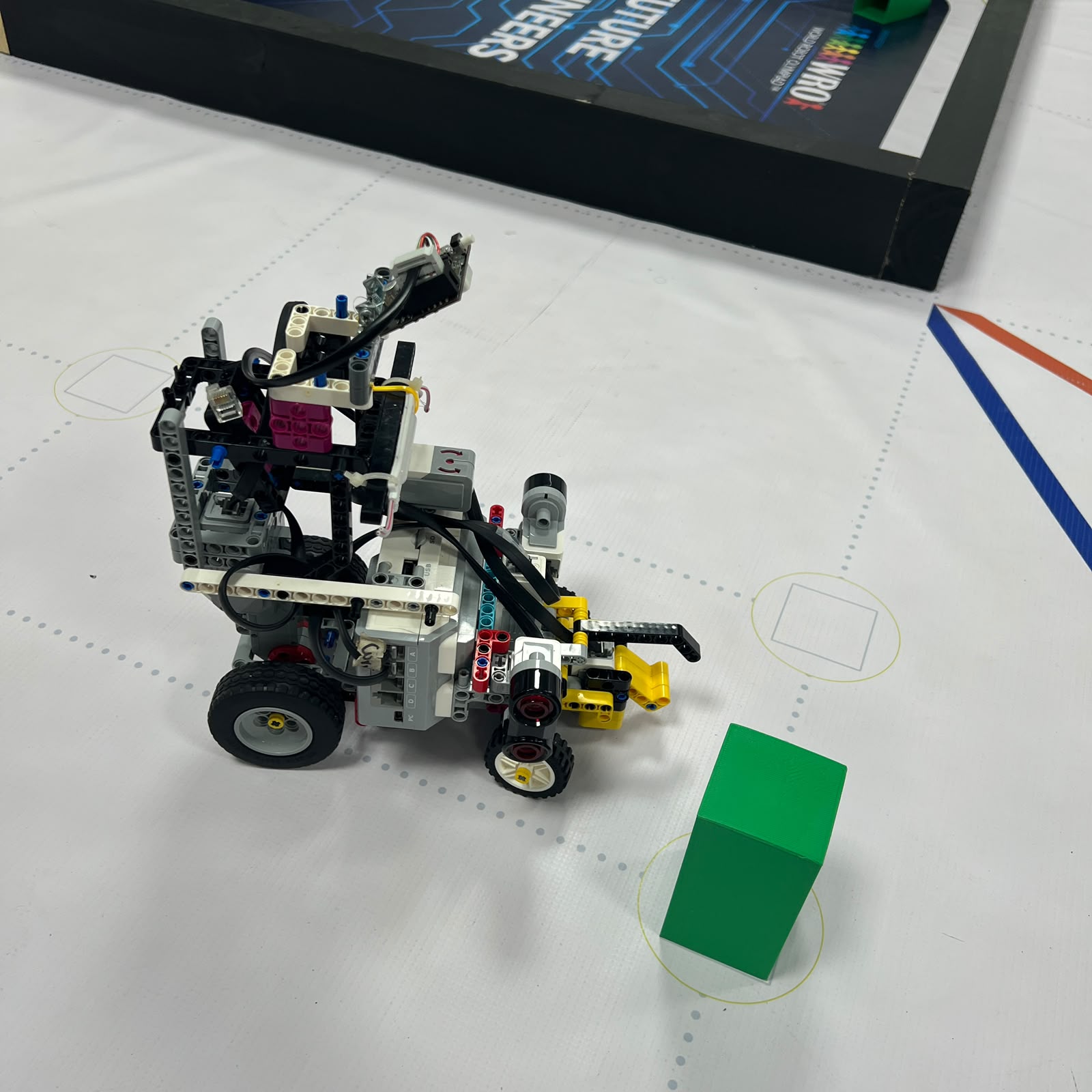 Figure 6.12. Representative green-pillar test used to evaluate the required pass-left trajectory.
For Green:
```text
GREEN
→ pass LEFT
```
The same test criteria apply.
Testing Red and Green separately is important because the physical steering system should not automatically be assumed to behave identically in both directions.
The comparison can reveal:
```text
left/right steering asymmetry
different recovery timing
different wall clearance
different camera geometry
```
---
# 6.29 Obstacle Recovery Test
One of the most important tests occurs **after** the pillar has been passed.
The robot should be evaluated for:
```text
residual steering angle
vehicle heading
distance from walls
readiness for next pillar
```
A failure can occur even after a technically correct pass.
For example:
```text
pillar successfully passed
↓
countersteering too late
↓
Piolín continues laterally
↓
wall collision
```
The obstacle test must therefore include recovery as part of the success criterion.
---
# 6.30 Consecutive-Pillar Testing
After single-pillar maneuvers are repeatable, several obstacles should be tested consecutively.
This determines whether:
```text
target state is released
steering recovers
camera geometry recovers
ultrasonic geometry becomes usable
next obstacle is approached correctly
```
A robot that passes an isolated pillar but fails when another appears immediately afterward does not yet have a complete obstacle-navigation solution.
---
# 6.31 Parking Testing
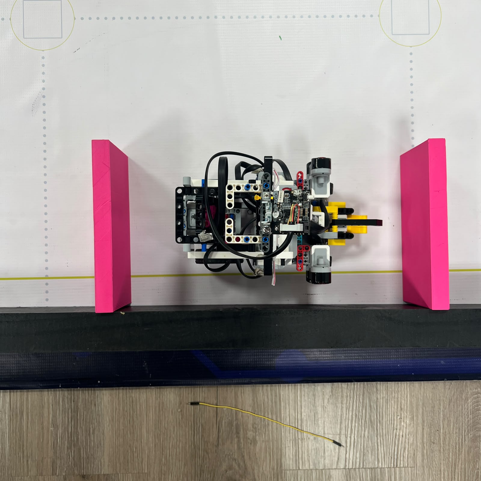 Figure 6.13. Parking area used to test final vehicle positioning.
Parking tests should begin separately from full autonomous runs.
A controlled parking test can establish:
```text
same approach position
same heading
same steering state
same propulsion displacement
```
and compare the final position across multiple attempts.
Useful observations include:
```text
longitudinal error
lateral error
final heading
steering position
whether the robot remains inside the required area
```
The final parking strategy is still under development, so no final success rate should be claimed until enough representative trials exist.
---
# 6.32 Full-Run Testing
Figure 6.14. Full-run testing combines every previously isolated mobility behavior into one continuous autonomous sequence.
A full run is the highest-level test.
It combines:
```text
starting behavior
straight driving
cornering
course progression
multiple laps
obstacles when applicable
recovery
parking
```
The full run should be performed only after the major isolated behaviors are reasonably stable.
Otherwise, a single failure can be difficult to diagnose because many subsystems are active simultaneously.
---
# 6.33 Why One Successful Run Is Not Enough
A single successful run demonstrates possibility.
It does not demonstrate repeatability.
Autonomous competition performance depends on the probability that the robot can reproduce the same behavior.
Therefore testing should emphasize:
```text
multiple trials
```
rather than:
```text
one best attempt
```
A useful result record can contain:
| Trial | Completed? | Main Failure / Observation |
| :---: | :---: | :--- |
| 1 | — | — |
| 2 | — | — |
| 3 | — | — |
| 4 | — | — |
| 5 | — | — |
The table should be filled with actual testing evidence rather than estimated performance.
---
# 6.34 Success Rate
Once enough comparable trials exist, a success rate can be calculated as:
```text
Success Rate =
Successful Trials
/
Total Trials
× 100%
```
For example, this can be calculated separately for:
```text
single left corner
single right corner
red pillar
green pillar
parking
complete Open run
complete Obstacle run
```
Separate success rates are more informative than combining unrelated maneuvers into one number.
The repository should only publish success rates when the test conditions and number of trials are documented.
---
# 6.35 Test Logging
Each significant test should record enough information to reproduce the conditions.
A useful log can contain:
| Field | Example of Information to Record |
| :--- | :--- |
| Date | Test date |
| Software version | File / commit / version |
| Challenge | Open or Obstacles |
| Battery condition | Measured or recorded state |
| Starting position | Track location / reference |
| Motor A setting | Active propulsion setting |
| Steering configuration | Relevant Motor B settings |
| Sensor configuration | Current S1 + S2/S3/S4 |
| Mechanical configuration | Any recent hardware change |
| Result | Success / failure / partial |
| Observation | What happened physically |
| Next change | Only the next variable to test |
This makes the development history easier to understand later.
---
# 6.36 Software Version Control During Testing
The code used during a successful test should be identifiable.
Otherwise, observations such as:
```text
this version turned better
```
become difficult to reproduce after several code changes.
A useful testing workflow is:
```text
save known code version
↓
run controlled trial
↓
record result
↓
change one parameter / behavior
↓
test again
```
Git commits or clearly named test versions can provide the software reference for each mechanical observation.
---
# 6.37 Mechanical Changes Must Be Logged
Software is not the only variable that should be documented.
Mechanical changes can include:
```text
Motor A remounted
Motor B remounted
steering linkage changed
wheel support reinforced
sensor mount moved
camera angle changed
chassis reinforcement added
```
Any of these can alter vehicle behavior.
If a mechanical change is made between two software tests but is not recorded, the resulting comparison can be misleading.
---
# 6.38 Battery as a Controlled Variable
The battery state should remain reasonably consistent when comparing mobility tests.
A different battery condition can change practical motor response.
This is especially relevant when comparing:
```text
vehicle speed
corner timing
reverse distance
parking
full-run time
```
The battery should therefore be considered a test condition rather than an invisible background variable.
---
# 6.39 Track Condition as a Controlled Variable
The track itself can also affect mobility.
Relevant variables include:
```text
surface cleanliness
pillar position
wall placement
parking configuration
starting position
```
A wheel may behave differently on a dusty or contaminated section of mat.
Likewise, moving an obstacle slightly can significantly change the required steering trajectory.
For meaningful comparisons, track conditions should be kept as consistent as practical.
---
# 6.40 Starting Position Repeatability
Autonomous tests should begin from a repeatable physical reference whenever possible.
A small starting-position difference can affect:
```text
first wall measurement
first steering correction
first corner entry
first obstacle approach
```
A test result should therefore distinguish between:
```text
controller failure
```
and:
```text
significantly different starting geometry
```
Starting position is particularly important during early Open acquisition and obstacle approach testing.
---
# 6.41 Testing at Competition Speed
Low-speed testing is useful because failures are easier to observe.
However, a controller that works slowly is not automatically validated at competition speed.
At higher speed:
```text
reaction distance increases
steering develops over more physical distance
corner timing changes
obstacle margin decreases
```
The testing progression should therefore be:
```text
low-speed validation
↓
intermediate-speed validation
↓
target competition-speed validation
```
rather than moving immediately to maximum available speed.
---
# 6.42 Failure Classification
A useful testing process classifies failures before changing parameters.
### Mechanical failure
Examples:
```text
wheel rubbing
linkage disconnected
drivetrain binding
Motor B mount moved
```
### Perception failure
Examples:
```text
wrong pillar selected
color not recognized
wall distance invalid
```
### Control failure
Examples:
```text
steering too strong
steering too weak
countersteering late
corner release early
```
### State failure
Examples:
```text
corner counted twice
target lock not released
parking triggered at wrong time
```
Separating the failure type prevents random parameter changes.
---
# 6.43 Failure Reproduction
When a failure occurs once, the next useful question is:
> **Can the same failure be reproduced under the same conditions?**
If the failure repeats consistently, it is easier to diagnose.
If it appears randomly, possible causes include:
```text
mechanical play
sensor variability
starting-position variation
lighting changes
software timing
target selection
```
The team should try to reproduce the condition before redesigning the entire controller.
---
# 6.44 One Change at a Time
A disciplined test cycle is:
```text
observe problem
↓
form hypothesis
↓
change one relevant variable
↓
repeat same test
↓
compare result
```
For example:
```text
Problem:
corner is too wide
Possible hypothesis:
steering begins too late
Change:
earlier corner-entry condition
Do NOT simultaneously:
increase Motor B angle
reduce Motor A speed
change gyro gain
move ultrasonic sensor
```
If four variables are changed at once and performance improves, the team does not know which one produced the improvement.
---
# 6.45 Test Matrix
A mobility test matrix can organize the main experiments.
| Test | Main Variable | Main Measurement / Observation |
| :--- | :--- | :--- |
| Steering center | Motor B return position | Center repeatability |
| Steering range | Motor B position | Mechanical limits |
| Steering symmetry | Left vs. right command | Wheel geometry / path |
| Straight-line test | Centered steering | Lateral drift |
| Encoder-distance | Motor A rotation | Physical displacement |
| Reverse test | Reverse rotation | Reverse displacement |
| Turning test | Steering command | Turning radius / path |
| Corner test | Entry + steering | Exit geometry |
| Red pillar | Pass-right maneuver | Clearance + recovery |
| Green pillar | Pass-left maneuver | Clearance + recovery |
| Parking | Final displacement | Final position |
| Full Open | Complete system | Completion + failure point |
| Full Obstacles | Complete system | Completion + failure point |
This matrix helps prevent testing from becoming a sequence of unrelated full runs.
---
# 6.46 Evidence Quality
Good engineering evidence should show:
```text
what was tested
how it was tested
what changed
what was measured
what happened
what decision followed
```
A statement such as:
> "The robot was better."
is much weaker than:
> "The same starting position and drive command were used. After reducing the steering response, the repeated left-right oscillation decreased during the same straight section."
The repository should prefer the second style.
---
# 6.47 Quantitative vs. Qualitative Tests
Not every useful observation must be numerical.
Quantitative evidence can include:
```text
distance
time
angle
success rate
number of trials
```
Qualitative evidence can include:
```text
visible binding
consistent drift direction
late countersteering
camera target leaving FOV
wheel rubbing
```
Both are useful when clearly documented.
The important requirement is that qualitative observations should not be presented as invented numerical measurements.
---
# 6.48 Current Testing Status
Piolín's mechanical architecture is current, but several performance values are still being calibrated.
The current testing process is actively focused on:
```text
Open corner consistency
initial course acquisition
multi-corner stability
Obstacle pillar selection
red/green passing consistency
countersteering
post-pillar recovery
parking
```
The repository should therefore distinguish:
```text
CURRENT ARCHITECTURE
```
from:
```text
FINAL VALIDATED PERFORMANCE
```
The first can be documented now.
The second should only be claimed after representative testing is complete.
---
# 6.49 Values That Should Come From Real Tests
The following should not be invented:
```text
straight-line deviation
steering repeatability
measured wheel angles
turning radius
encoder-distance scale
reverse-distance error
corner success rate
red-pillar success rate
green-pillar success rate
parking success rate
Open full-run success rate
Obstacle full-run success rate
average run time
fastest validated run
```
These values become strong engineering evidence only when accompanied by a real test method and enough trials.
---
# 6.50 Suggested Test Record
A compact test record can use the following format:
```text
TEST ID:
DATE:
CHALLENGE:
OPEN / OBSTACLES
SOFTWARE VERSION:
HARDWARE CONFIGURATION:
BATTERY CONDITION:
START POSITION:
VARIABLE CHANGED:
EXPECTED RESULT:
ACTUAL RESULT:
FAILURE POINT:
MECHANICAL OBSERVATION:
NEXT CHANGE:
```
Using a consistent record prevents important development information from being lost between sessions.
---
# 6.51 Testing Loop
The full development process can be summarized as:
```text
BUILD
↓
INSPECT
↓
CALIBRATE
↓
TEST
↓
OBSERVE
↓
CLASSIFY FAILURE
↓
CHANGE ONE VARIABLE
↓
RETEST
↓
COMPARE
↓
KEEP / REJECT CHANGE
```
This process applies equally to mechanical and software development.
It also explains why failed prototypes remain useful: a failed experiment can still identify a limit or eliminate an incorrect assumption.
---
# 6.52 Full-System Mechanical Evidence
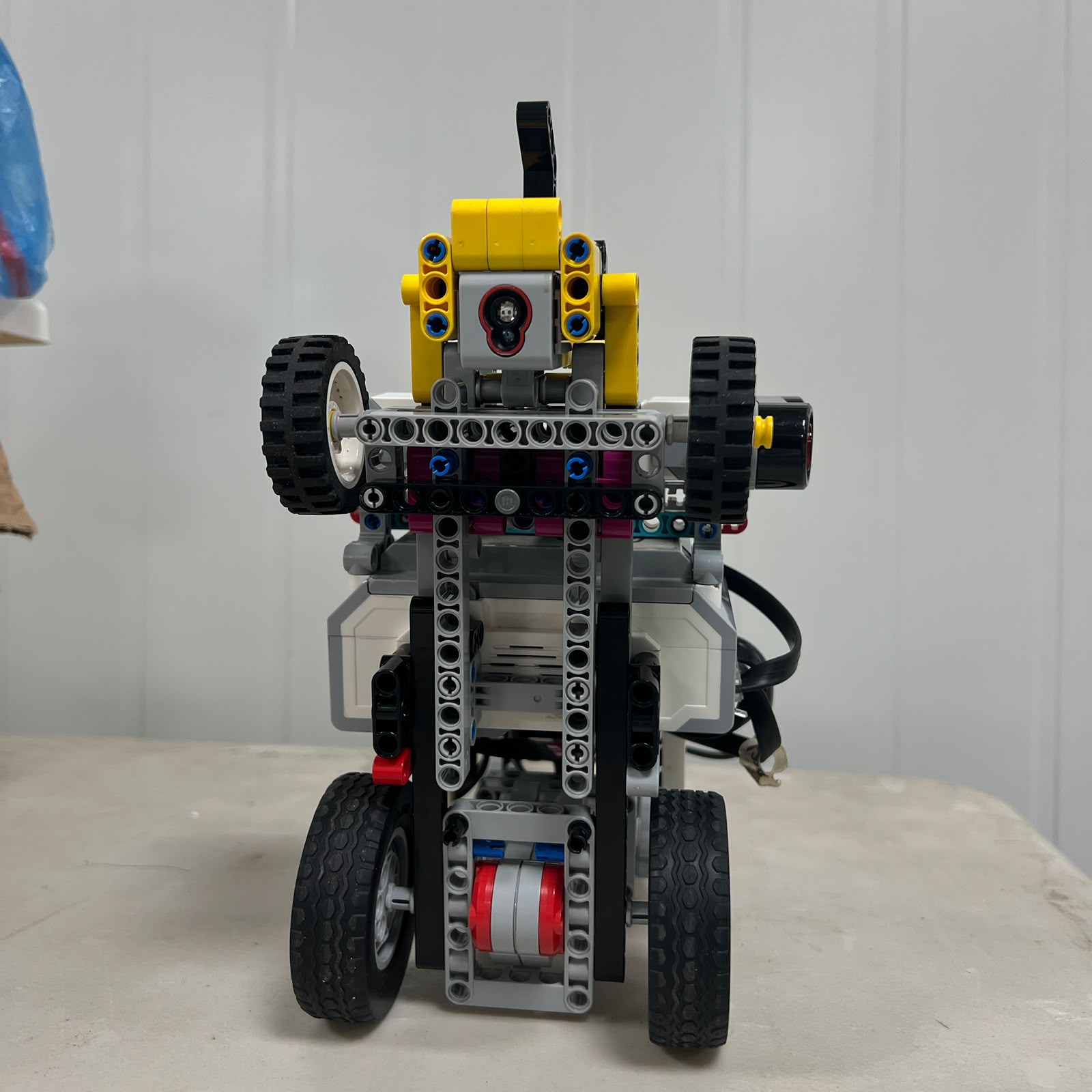 Figure 6.15. Mobility testing evaluates the complete physical system rather than treating drivetrain, steering, and chassis as unrelated mechanisms.
A navigation result is produced by the interaction of:
```text
chassis
drivetrain
rear wheels
steering mechanism
front wheels
motors
sensors
software
```
A test must therefore consider whether a behavior originated from one subsystem or from the interaction between several.
This systems perspective is especially important during full runs.
---
# 6.53 Final Engineering Assessment
Piolín's mobility and mechanical testing process is designed to convert observations into engineering decisions.
The goal is not to produce the largest number of test runs.
The goal is to produce tests that answer specific questions.
The most important sequence is:
```text
verify mechanical condition
↓
isolate the behavior
↓
control test variables
↓
repeat the experiment
↓
measure or observe the result
↓
identify the failure layer
↓
change one relevant variable
↓
test again
```
This approach is particularly important for Piolín because its autonomous performance depends on the close interaction between a mechanical Ackermann steering system, a single rear drivetrain, multiple sensors, and two different round-specific perception architectures.
A corner failure may originate from steering timing.
A straight-line failure may originate from mechanical center.
A parking error may originate from drivetrain displacement.
An obstacle failure may originate from visual perception even though it appears as incorrect steering.
Testing allows these causes to be separated.
The final engineering principle is therefore:
> **Piolín is not considered mechanically successful because it can perform one correct run; the mechanical system is successful when the same known conditions produce sufficiently repeatable physical behavior for autonomous control.**
For this reason, repeatability, controlled variables, documented failures, and measured evidence form a central part of Piolín's mechanical-development process.
---
### [← Back to PiolínTech Main README](../../README.md)