# 1. Power and Sensor Configuration
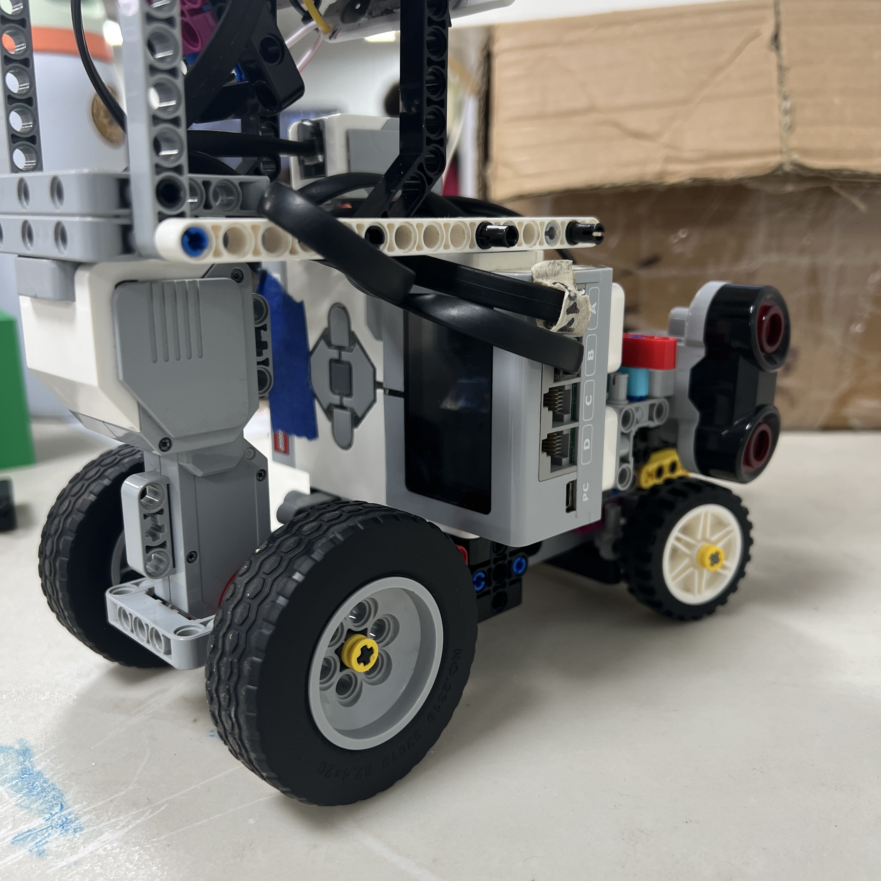 Figure 1.1. LEGO Mindstorms EV3 Brick installed as the central power, sensing, and control platform of Piolín.
Piolín uses a **round-specific sensor architecture** built around one LEGO Mindstorms EV3 Brick, one EV3 Rechargeable DC Battery 45501, two motors, two permanent lateral ultrasonic sensors, one permanent downward-facing Color Sensor, and one specialized device on Sensor Port S1.
The key design decision is that **S1 changes according to the competition round**.
```text
OPEN CHALLENGE
S1 → EV3 Gyro Sensor
S2 → Left Ultrasonic Sensor
S3 → Right Ultrasonic Sensor
S4 → Color Sensor
```
```text
OBSTACLE CHALLENGE
S1 → Pixy2.1
S2 → Left Ultrasonic Sensor
S3 → Right Ultrasonic Sensor
S4 → Color Sensor
```
The drivetrain remains unchanged:
```text
Motor A → EV3 Large Motor → propulsion
Motor B → EV3 Medium Motor → steering
```
The Gyro Sensor and Pixy2.1 are therefore **never part of the active robot at the same time**.
This architecture allows Piolín to dedicate the limited EV3 sensor ports to the type of information that matters most in each challenge while keeping the rest of the vehicle physically consistent.
---
## 1.1 Central EV3 Architecture
The EV3 is the central point of Piolín's electrical and sensing architecture.
It performs several functions simultaneously:
```text
power distribution
sensor communication
sensor interpretation
navigation logic
motor control
diagnostics
```
The overall system can be represented as:
```text
BATTERY 45501
│
▼
EV3
│
┌──────────────┼──────────────┐
│ │ │
▼ ▼ ▼
Motor A Motor B Sensor Ports
│ │ │
▼ ▼ ┌───────┼────────┐
Drive Steering S1 S2/S3 S4
│ │ │
│ ▼ ▼
round-specific US Color
```
This centralized arrangement avoids the need for a separate primary controller or independent motor-control system.
---
# 1.2 Main Power Source
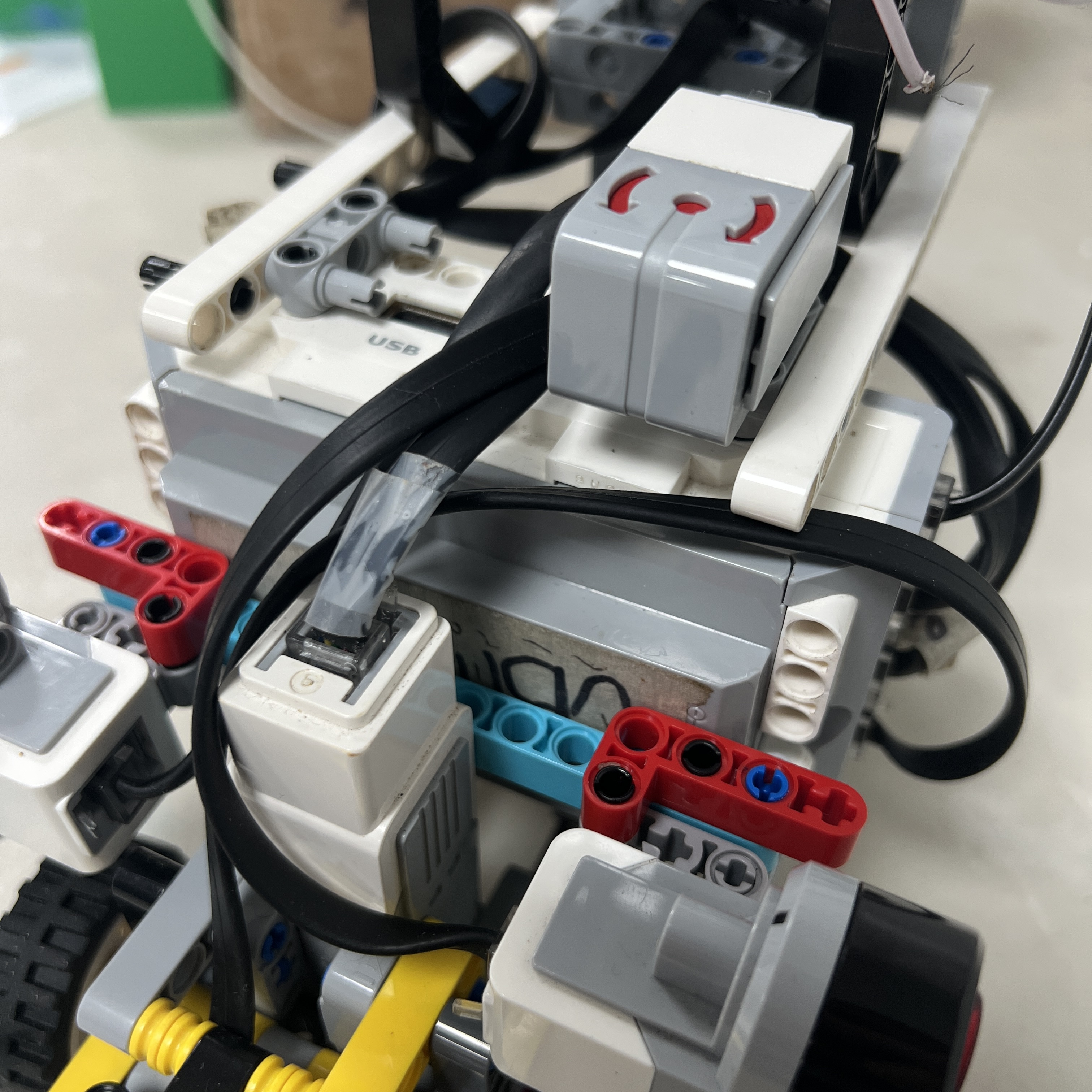 Figure 1.2. LEGO Mindstorms EV3 Rechargeable DC Battery 45501 used as Piolín's main competition power source.
Piolín uses the **LEGO Mindstorms EV3 Rechargeable DC Battery 45501** as its main power source.
The battery is installed directly into the EV3 Brick and supports the same centralized architecture in both competition rounds.
The high-level power path is:
```text
EV3 Battery 45501
↓
EV3 Brick
↓
motors + sensors + round-specific S1 device
```
The current competition architecture does not use:
```text
external propulsion battery
separate battery for vision
permanent buck converter
Arduino Nano power subsystem
```
The power architecture therefore remains intentionally compact.
---
# 1.3 Motor Configuration
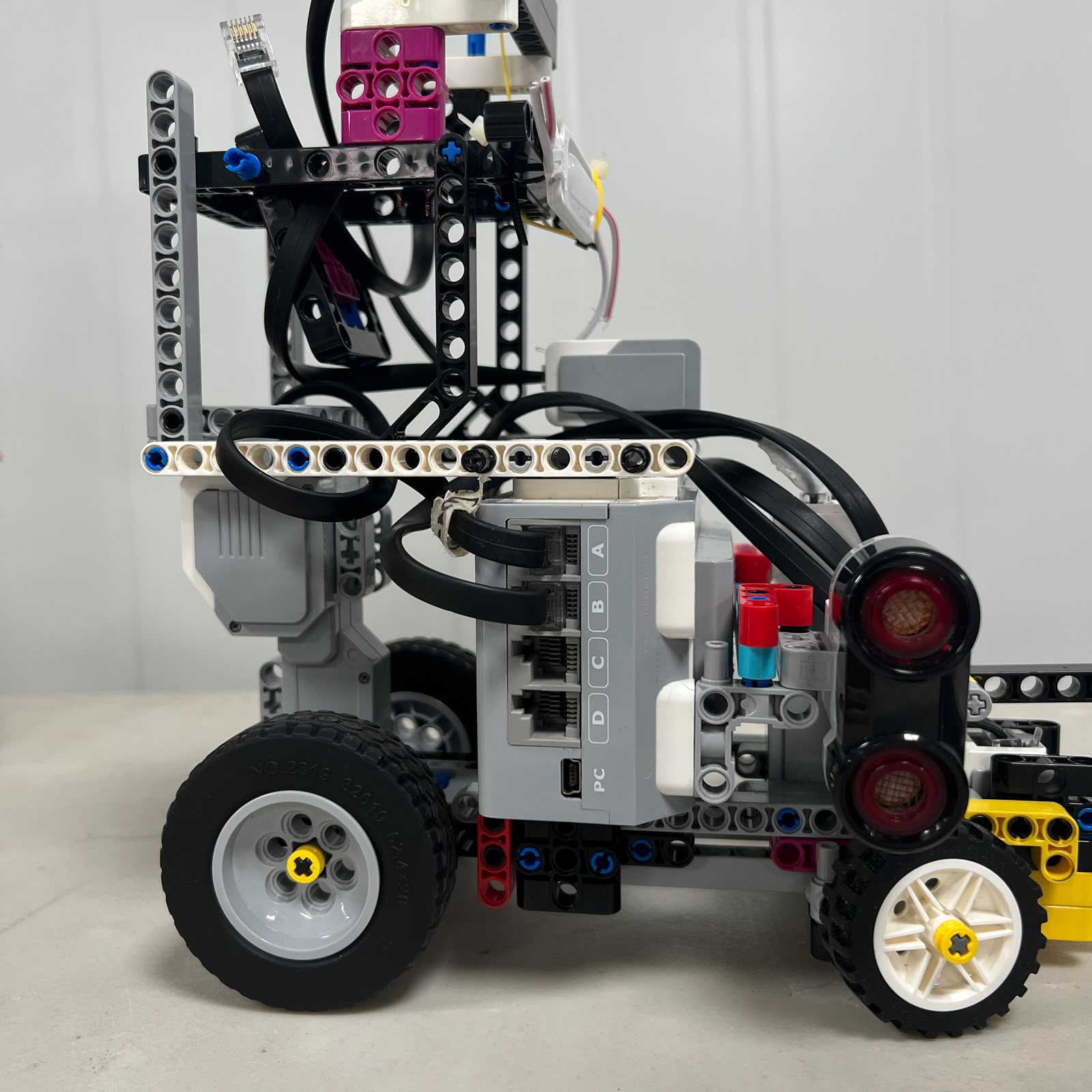 Figure 1.3. Motor Ports A and B provide the interfaces for Piolín's two vehicle actuators.
Piolín uses only two motors.
| EV3 Motor Port | Component | Function |
| :---: | :--- | :--- |
| A | EV3 Large Motor | Rear propulsion |
| B | EV3 Medium Motor | Front steering |
This assignment is permanent in both rounds.
The architecture deliberately separates:
```text
Motor A
→ longitudinal motion
```
from:
```text
Motor B
→ vehicle direction
```
No differential-drive configuration is used.
---
# 1.4 Sensor Port Configuration
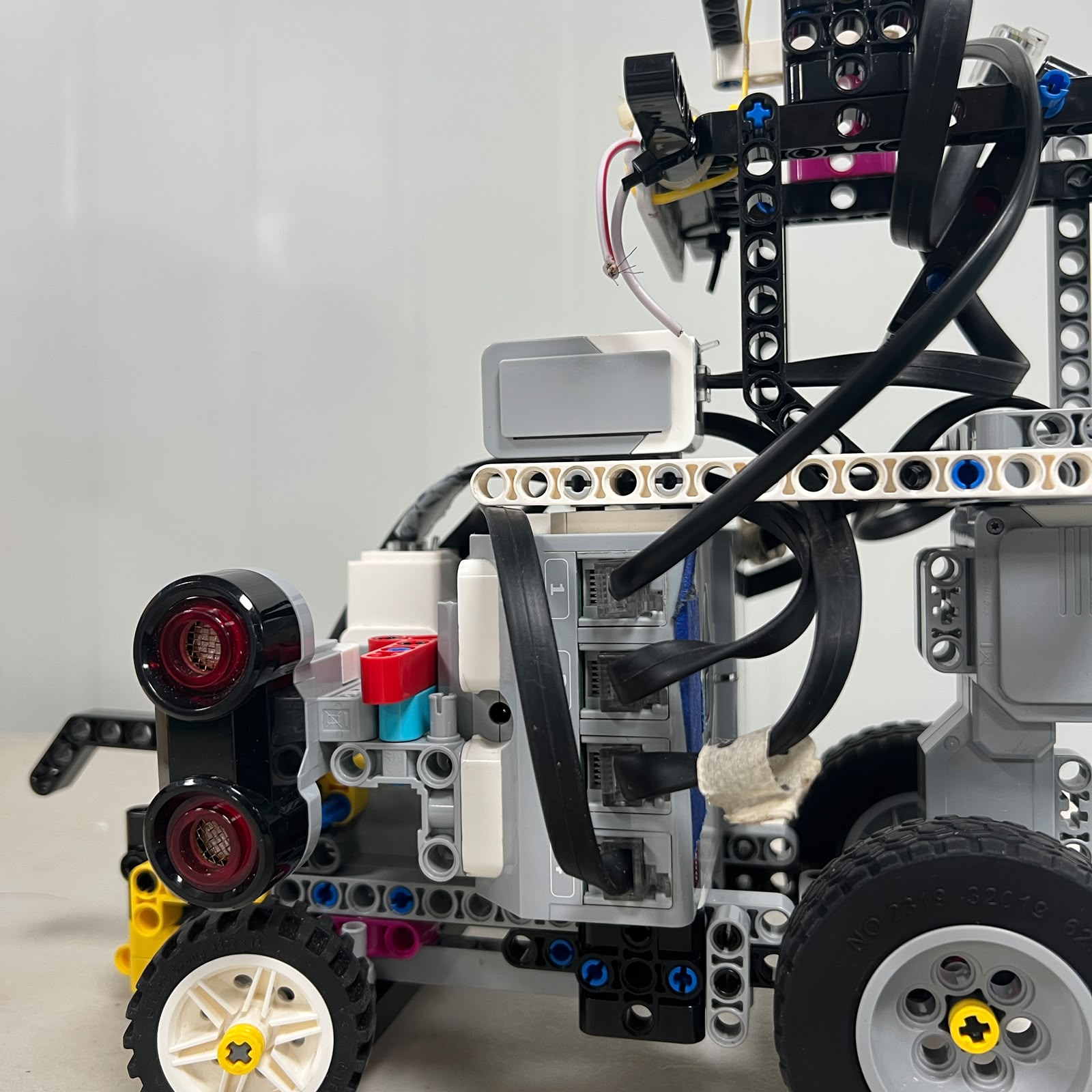 Figure 1.4. EV3 sensor-port interface. S2, S3, and S4 remain fixed while S1 changes between competition rounds.
The current sensor-port philosophy is:
```text
S1
→ specialized round-specific information
S2
→ permanent LEFT geometry
S3
→ permanent RIGHT geometry
S4
→ permanent floor-state information
```
This creates a stable physical sensor mapping while preserving one flexible port.
The most important fixed convention is:
```text
S2 = LEFT
S3 = RIGHT
```
This mapping does not change with course direction.
---
# 1.5 Why S1 Is Round-Specific
The two WRO Future Engineers challenges require different types of information.
During Open, Piolín needs a strong reference for:
```text
heading
rotation
corner progress
```
During Obstacles, it needs:
```text
pillar identity
pillar image position
visual target information
```
One device cannot provide both types of information equally well.
Instead of adding another controller simply to keep every sensor connected simultaneously, Piolín changes the S1 sensor according to the round.
```text
OPEN
→ orientation is more valuable
→ Gyro on S1
```
```text
OBSTACLES
→ visual classification is essential
→ Pixy2.1 on S1
```
This is a deliberate sensor-allocation decision rather than a temporary wiring workaround.
---
# 1.6 Open Challenge Sensor Configuration
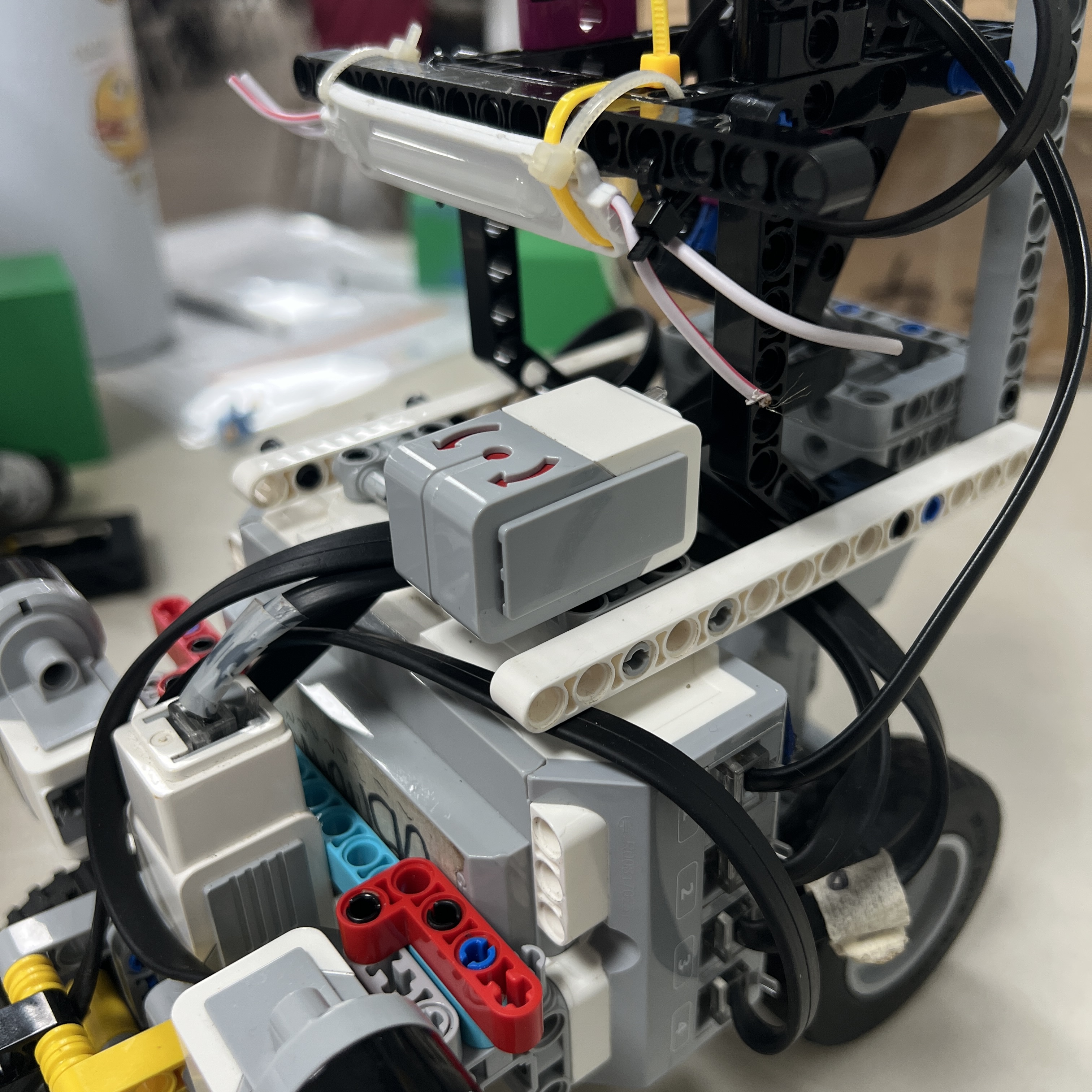 Figure 1.5. Open Challenge configuration with the EV3 Gyro Sensor occupying S1.
The Open configuration is:
| Port | Device | Main Role |
| :---: | :--- | :--- |
| S1 | EV3 Gyro Sensor | Heading and rotational reference |
| S2 | Left Ultrasonic Sensor | Left-side geometry |
| S3 | Right Ultrasonic Sensor | Right-side geometry |
| S4 | EV3 Color Sensor | Floor landmarks and course progress |
Motor configuration remains:
```text
A → propulsion
B → steering
```
This round uses only LEGO EV3 sensing hardware.
---
# 1.7 Gyro Role During Open
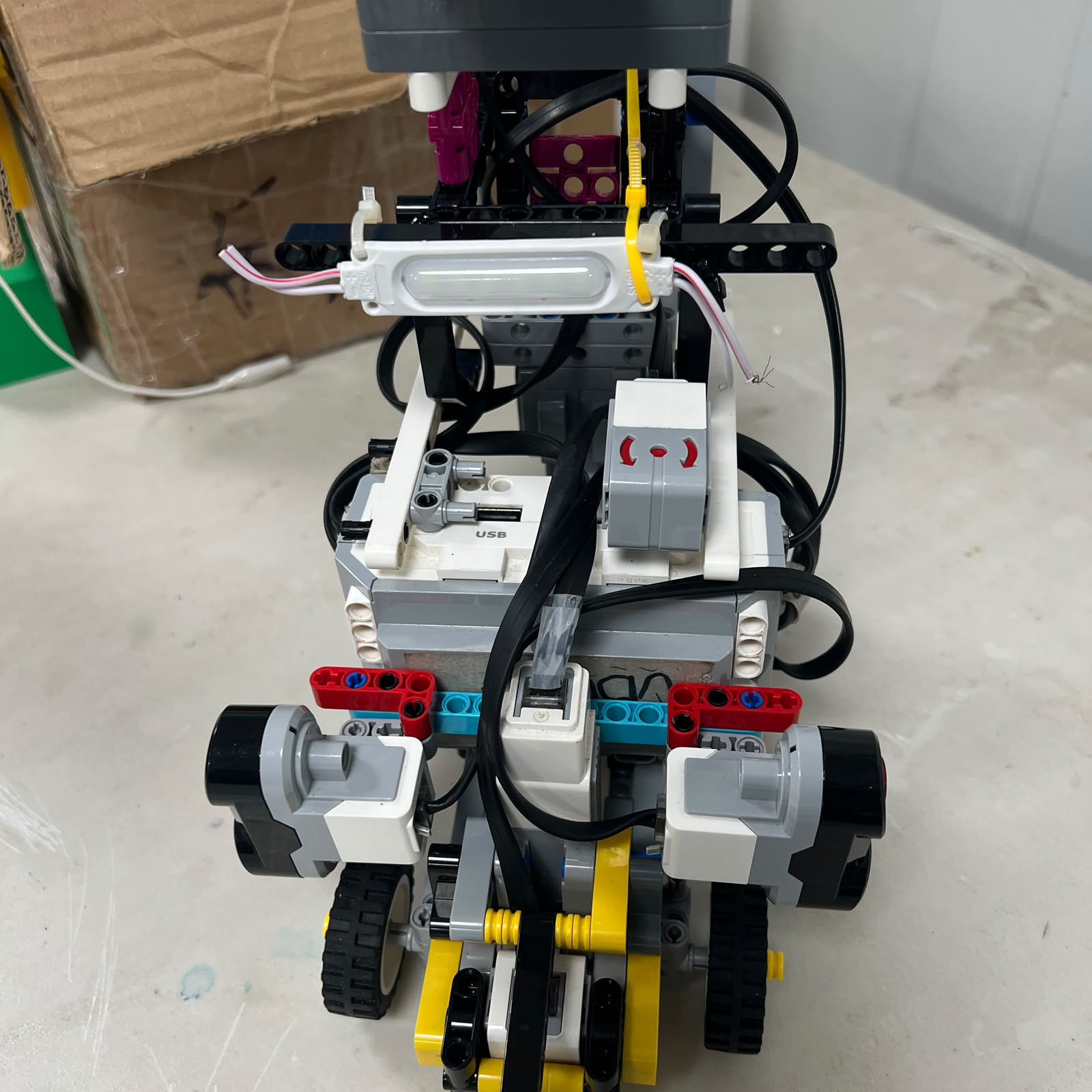 Figure 1.6. Physical gyro orientation relative to the vehicle chassis.
The Gyro Sensor provides information about vehicle rotation.
At the beginning of the current Open program, the gyro reference is reset so that the initial heading becomes the local zero reference.
Conceptually:
```text
START
↓
reset gyro
↓
current heading = reference
```
The gyro can then support:
```text
straight-line heading stabilization
drift reduction
corner progression
corner-exit confirmation
```
The gyro does not replace the ultrasonic sensors.
The two sensing systems measure different aspects of the vehicle state.
```text
Gyro
→ orientation
Ultrasonics
→ lateral geometry
```
Combining them gives the EV3 more information than either sensor type alone.
---
# 1.8 Open Sensor Fusion
During approximately straight driving, Piolín can separate the navigation problem into:
```text
WHERE IS THE VEHICLE LATERALLY?
→ S2 / S3
```
and:
```text
HOW IS THE VEHICLE ORIENTED?
→ Gyro
```
This distinction is important.
A robot may be at an acceptable wall distance but rotated incorrectly.
Similarly, it may have the correct heading while being too close to one wall.
The Open architecture therefore combines:
```text
lateral position information
+
heading information
+
floor-state information
```
before Motor B determines the physical steering response.
---
# 1.9 Lateral Ultrasonic Sensors
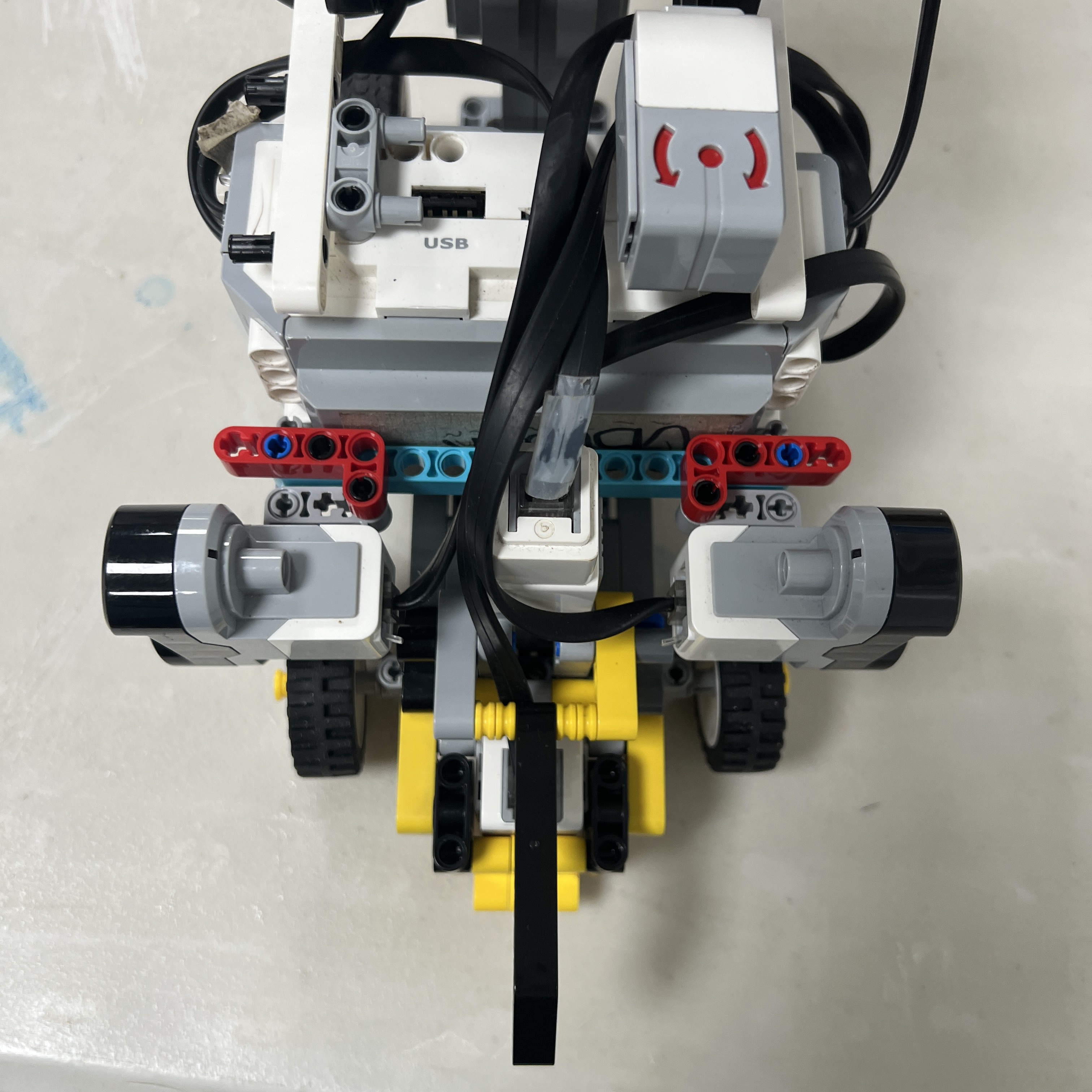 Figure 1.7. Two permanent lateral EV3 Ultrasonic Sensors provide left and right track-geometry information.
Piolín currently uses **exactly two ultrasonic sensors**.
There is no permanent front ultrasonic sensor in the final architecture.
Their fixed mapping is:
```text
S2
→ LEFT Ultrasonic Sensor
S3
→ RIGHT Ultrasonic Sensor
```
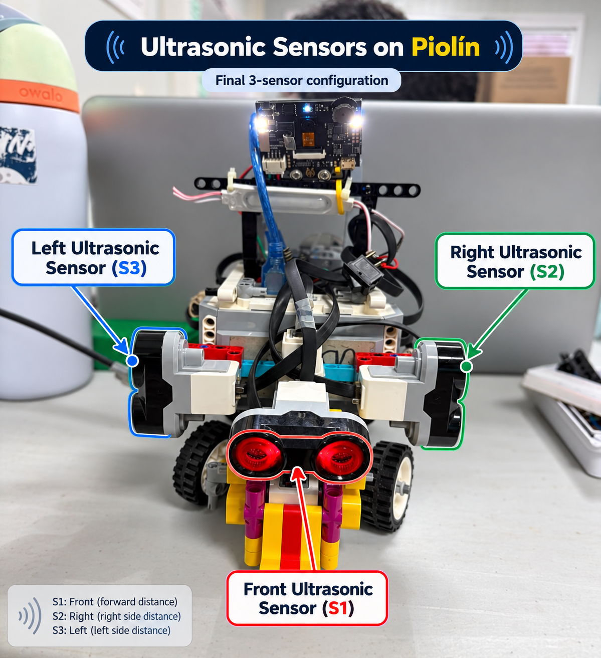 Figure 1.8. Physical ultrasonic mapping used throughout current hardware and software documentation.
The left/right identity remains physical and permanent.
The software can later reinterpret either sensor as:
```text
INNER
```
or:
```text
OUTER
```
depending on course direction.
---
# 1.10 Inner and Outer Mapping
During counterclockwise Open navigation:
```text
LEFT side
→ inner side
RIGHT side
→ outer side
```
therefore:
```text
S2
→ inner
S3
→ outer
```
During clockwise navigation:
```text
RIGHT side
→ inner side
LEFT side
→ outer side
```
therefore:
```text
S3
→ inner
S2
→ outer
```
The physical ports never swap.
Only their navigational meaning changes.
This separation between:
```text
physical sensor identity
```
and:
```text
logical navigation role
```
prevents the wiring architecture from becoming dependent on course direction.
---
# 1.11 Ultrasonic Orientation
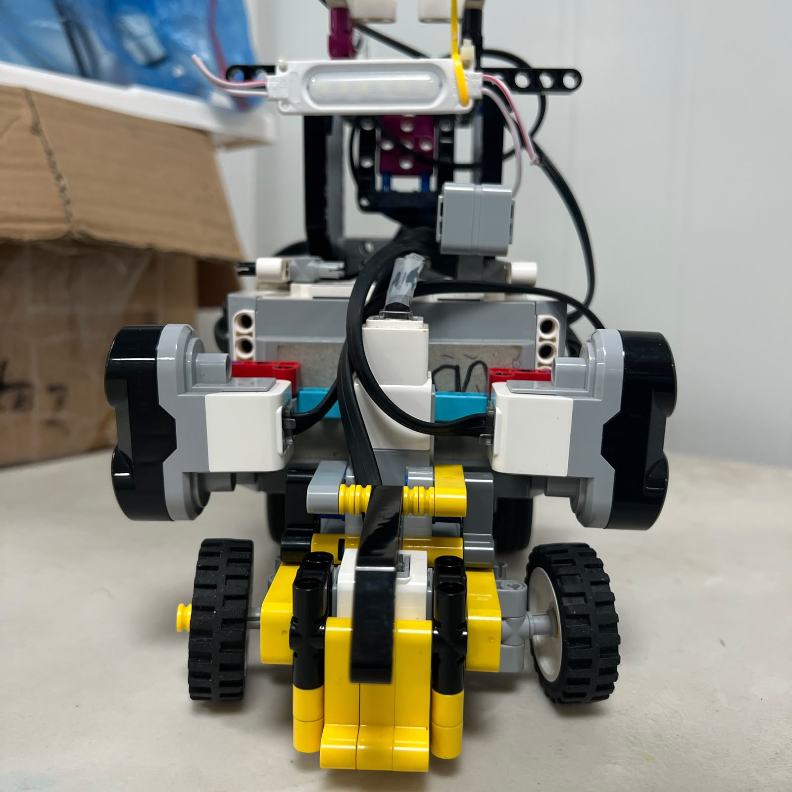 Figure 1.9. Current ultrasonic sensors are mounted laterally rather than as forward-facing or diagonal range sensors.
The current sensors observe the track boundaries from the sides of the robot.
This differs from earlier Piolín experiments that considered or used different ultrasonic orientations.
The lateral arrangement is intended to provide information about:
```text
distance to left boundary
distance to right boundary
corridor geometry
corner geometry changes
post-obstacle recovery
```
Because their interpretation depends on vehicle orientation, ultrasonic values are not treated as perfect global-position measurements.
---
# 1.12 Ultrasonic Mounting Stability
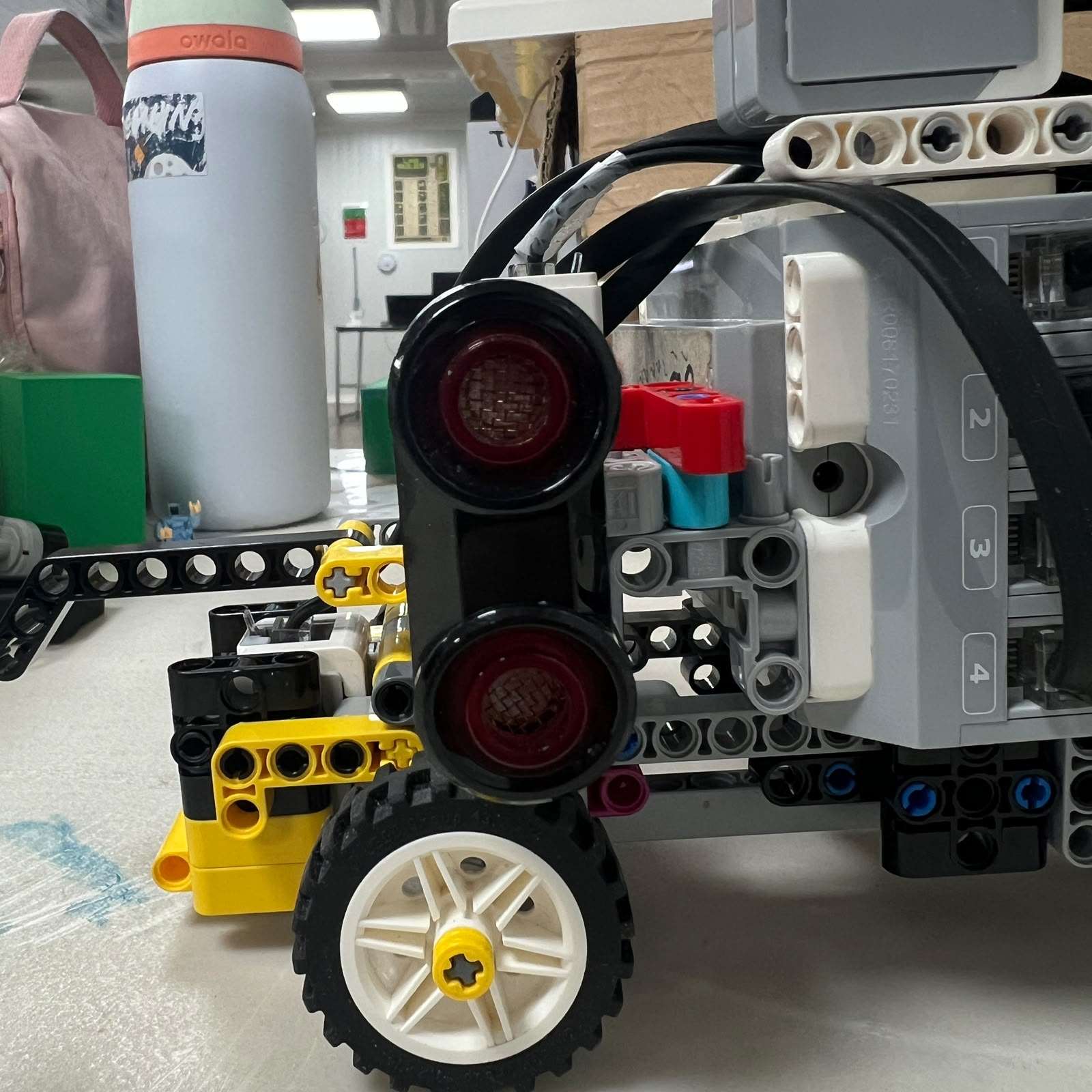 Figure 1.10. Sensor mounting must preserve lateral orientation so calibration remains physically meaningful.
A distance sensor is only useful if its physical reference remains stable.
If one sensor rotates slightly:
```text
same wall
+
different sensor orientation
=
different measured geometry
```
The ultrasonic mounts therefore form part of the sensing system.
Before changing wall-following software because readings behave differently, the physical mounts should first be inspected.
---
# 1.13 Color Sensor Configuration
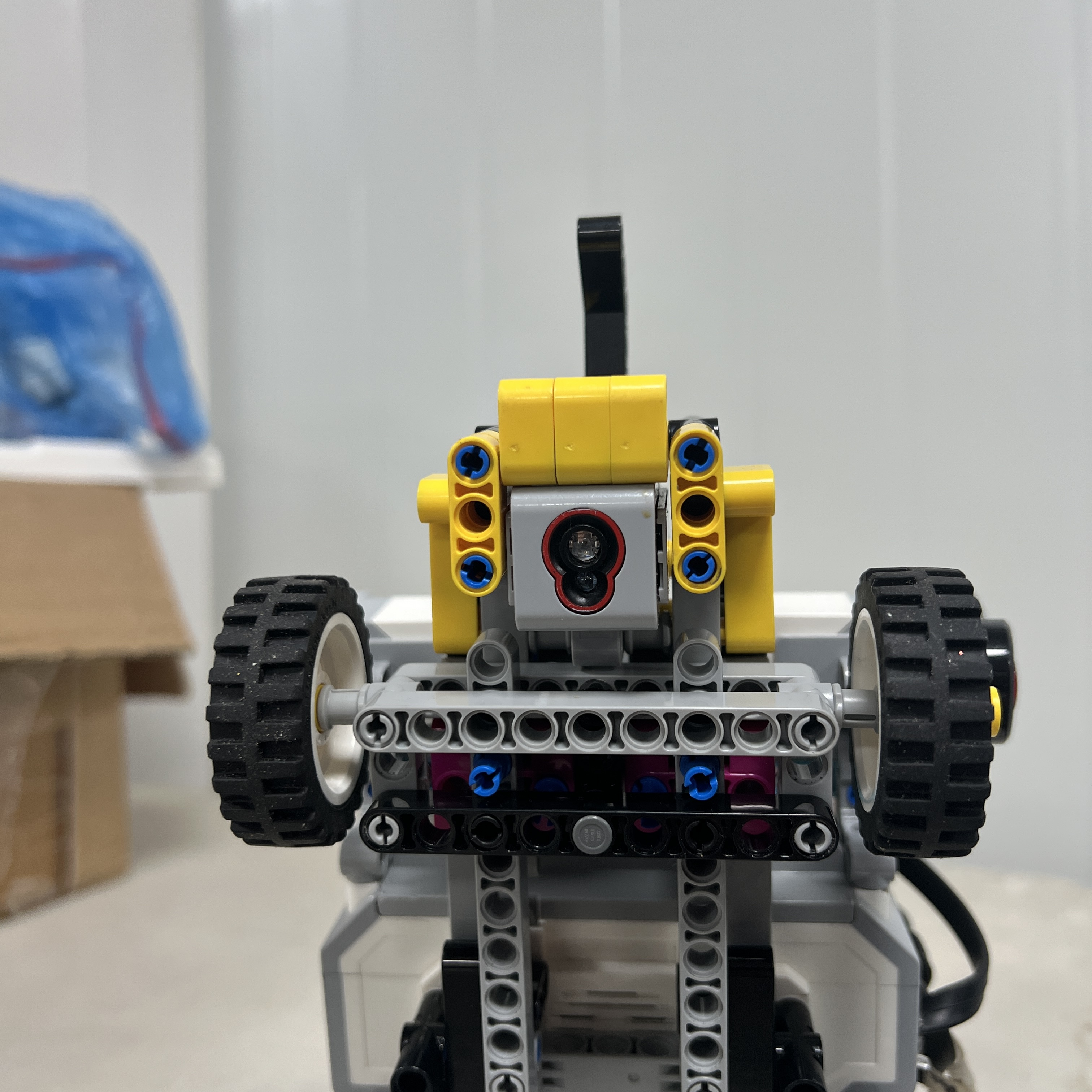 Figure 1.11. EV3 Color Sensor permanently installed on S4 and directed toward the floor.
The EV3 Color Sensor remains connected to **S4 in both competition rounds**.
Its purpose is different from the lateral sensors.
It does not determine wall distance or vehicle heading.
Instead, it provides information about the competition surface directly below the robot.
The current main floor references are:
```text
BLUE
ORANGE
```
These markings are used as physical course landmarks.
---
# 1.14 Initial Course Direction
During Open, the first valid floor marking establishes the course direction.
```text
BLUE first
→ COUNTERCLOCKWISE
```
```text
ORANGE first
→ CLOCKWISE
```
Once the direction has been determined, it should be treated as a persistent course state rather than repeatedly reversed whenever another floor marking is encountered.
Later valid detections primarily contribute to:
```text
course progression
corner count
lap progression
```
rather than redefining the original direction.
---
# 1.15 Color Sensor Physical Environment
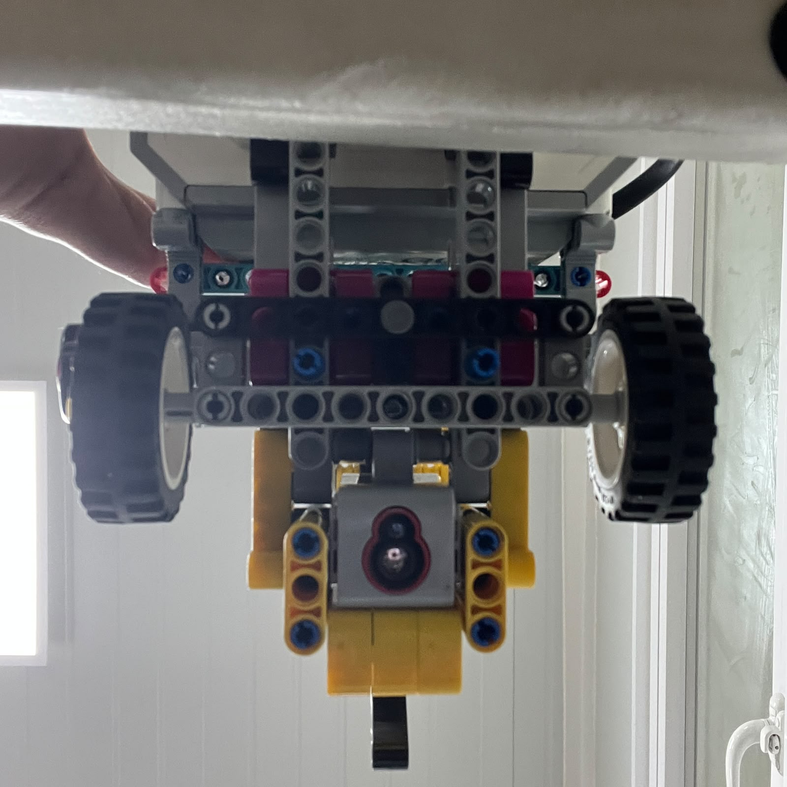 Figure 1.12. Downward-facing S4 sensor observes the competition floor directly beneath the vehicle.
The Color Sensor measurement depends on more than software thresholds.
Its physical reading can also be affected by:
```text
sensor height
ambient light
vehicle motion
surface condition
sensor angle
```
Piolín therefore uses a physical light-isolation solution around the sensor.
---
# 1.16 Color Sensor Light Casing
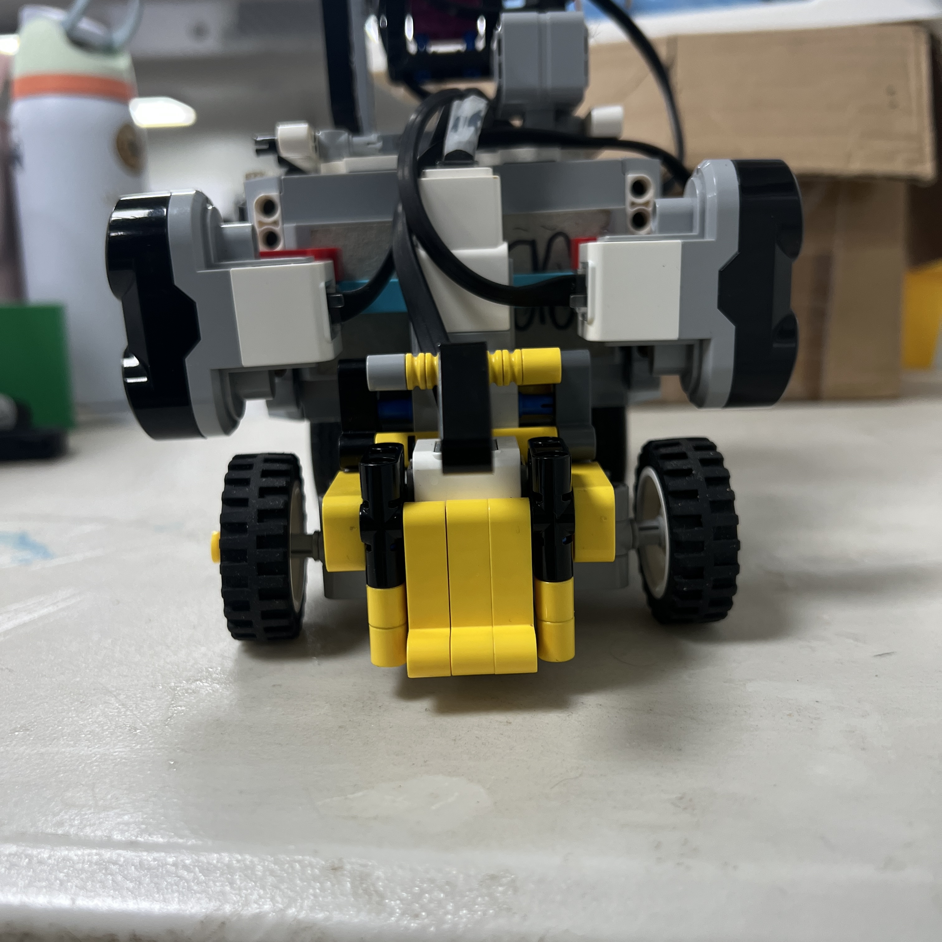 Figure 1.13. Custom casing reduces uncontrolled external illumination around the Color Sensor.
The casing was introduced to improve the physical measurement environment before relying entirely on software filtering.
The design principle is:
```text
reduce uncontrolled light
↓
improve measurement consistency
↓
simplify classification
```
This is an example of solving part of a sensing problem mechanically rather than attempting to correct everything through code.
---
# 1.17 Real Floor References
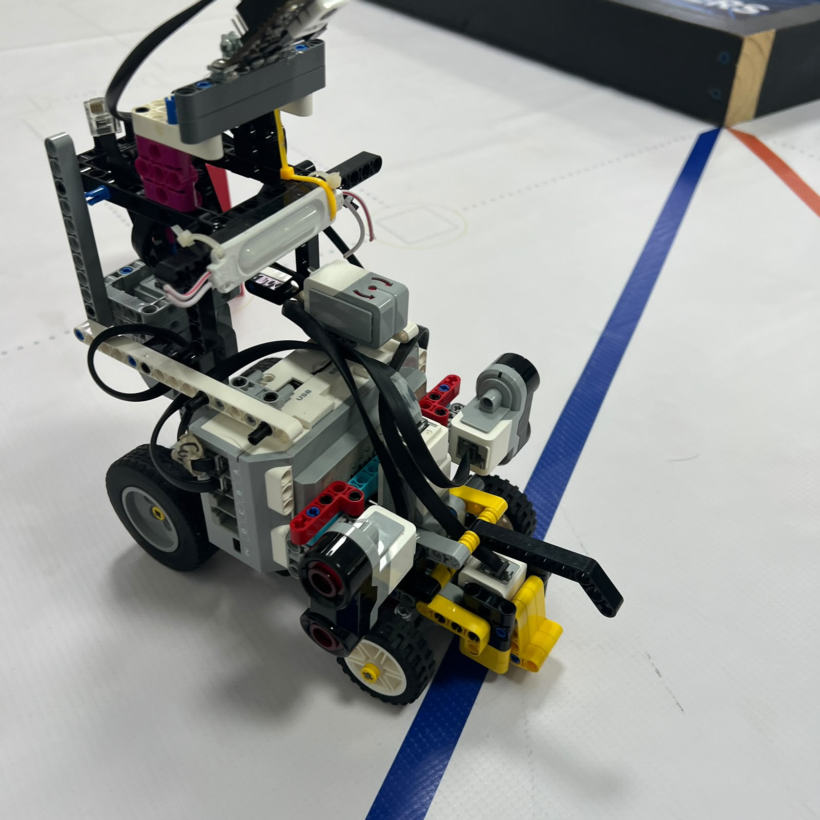 Figure 1.14. S4 observing a blue physical course reference.
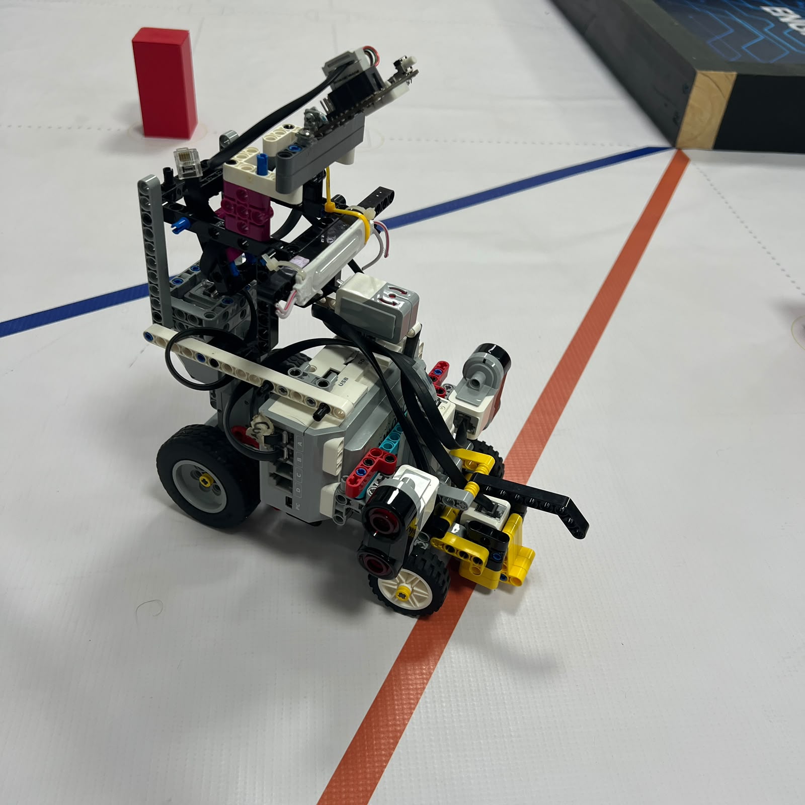 Figure 1.15. S4 observing an orange physical course reference.
The Color Sensor should be calibrated against the real physical markings under representative conditions.
The repository should avoid publishing a final classification threshold until it has been validated using the current sensor mounting and light casing.
---
# 1.18 Open Challenge Information Roles
The complete Open sensing architecture can be summarized as:
| Information Needed | Primary Source |
| :--- | :--- |
| Vehicle heading | Gyro S1 |
| Left wall geometry | Ultrasonic S2 |
| Right wall geometry | Ultrasonic S3 |
| Initial course direction | Color Sensor S4 |
| Course progress | Color Sensor S4 |
| Propulsion rotation | Motor A encoder |
| Steering rotation | Motor B encoder |
This division reduces unnecessary overlap between sensors.
Each device provides a specific type of information to the EV3.
---
# 1.19 Obstacle Challenge Configuration
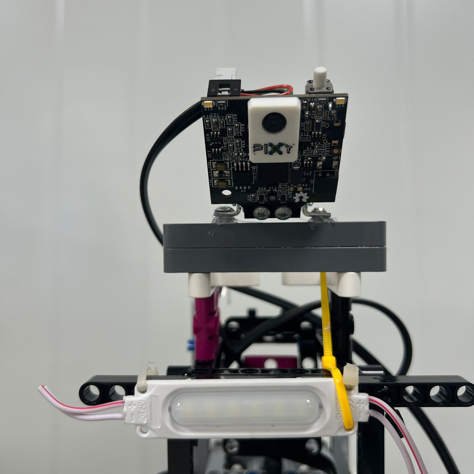 Figure 1.16. During Obstacles, Pixy2.1 replaces the Gyro Sensor on S1.
The active Obstacle configuration is:
| Port | Device | Main Role |
| :---: | :--- | :--- |
| S1 | Pixy2.1 | Visual obstacle detection and localization |
| S2 | Left Ultrasonic Sensor | Left wall and obstacle-side geometry |
| S3 | Right Ultrasonic Sensor | Right wall and obstacle-side geometry |
| S4 | Color Sensor | Floor/course-state reference |
The Gyro Sensor is not installed during this round.
This distinction should remain explicit throughout the repository.
---
# 1.20 Pixy2.1 Integration
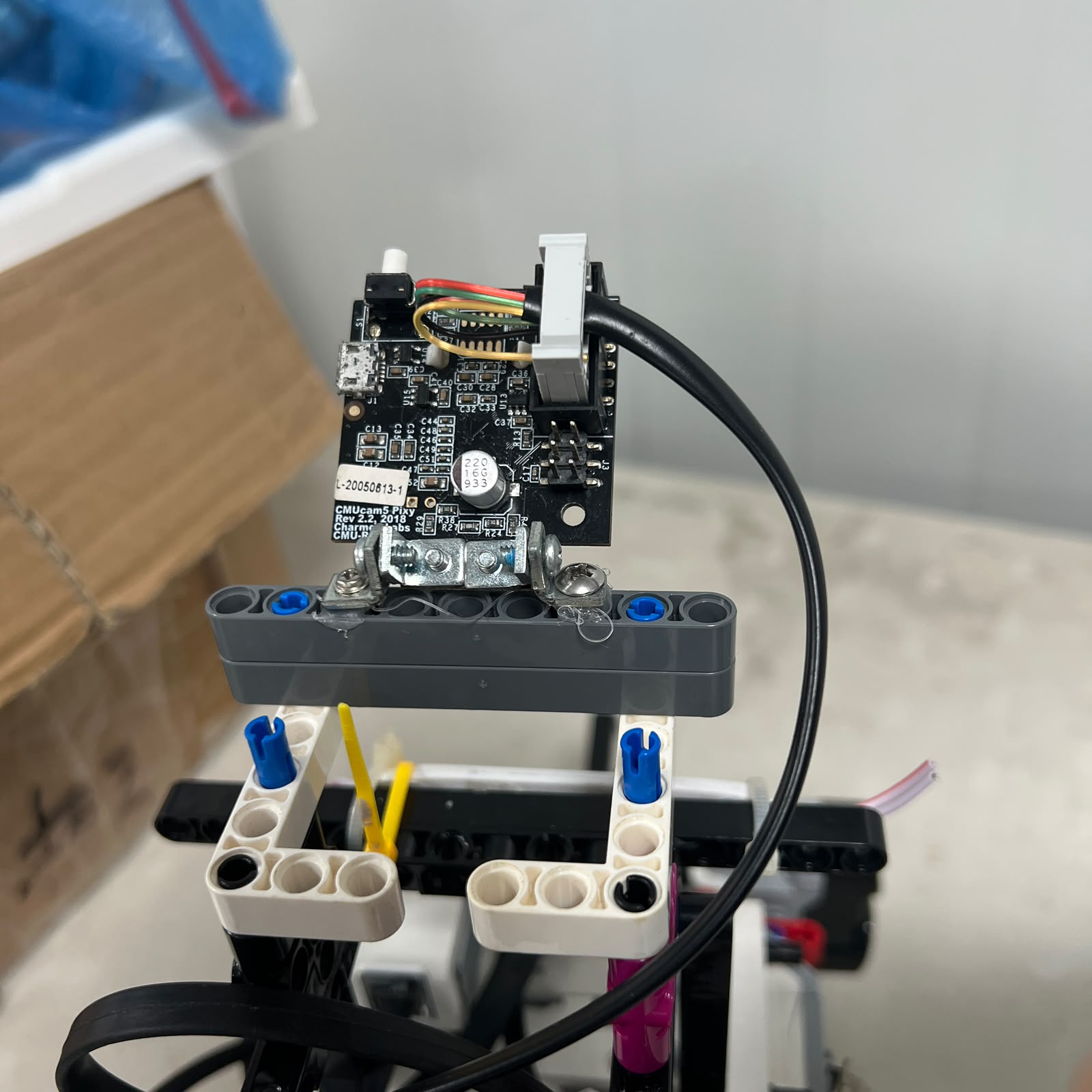 Figure 1.17. Current Pixy2.1-to-EV3 connection used in the Obstacle Challenge configuration.
Pixy2.1 connects directly to the EV3 through the current S1 interface.
The current software architecture reads the visual sensor using an I2C/SMBus-based path in the Obstacle Challenge implementation.
The hardware chain is:
```text
Pixy2.1
↓
S1
↓
EV3
```
This is substantially simpler than the previous vision architecture that required an intermediate Arduino Nano.
---
# 1.21 Pixy Visual Information
Pixy2.1 provides visual block information that can include:
```text
signature
x
y
width
height
```
These values answer different questions.
```text
signature
→ what target was recognized?
```
```text
x / y
→ where does it appear in the image?
```
```text
width / height
→ how large does it appear?
```
Apparent image size can help determine relevance but should not automatically be interpreted as exact metric distance without calibration.
---
# 1.22 Current Pixy Signature Mapping
The current Piolín mapping is:
| Pixy Signature | Target | Navigation Meaning |
| :---: | :--- | :--- |
| 1 | Pink | Parking reference |
| 2 | Red | Pass right |
| 3 | Green | Pass left |
Therefore:
```text
RED
→ RIGHT
```
and:
```text
GREEN
→ LEFT
```
These directions describe the side on which Piolín must pass the pillar.
They should not be interpreted as a permanent maximum steering command.
The EV3 must still determine the complete trajectory.
---
# 1.23 Red Visual Detection
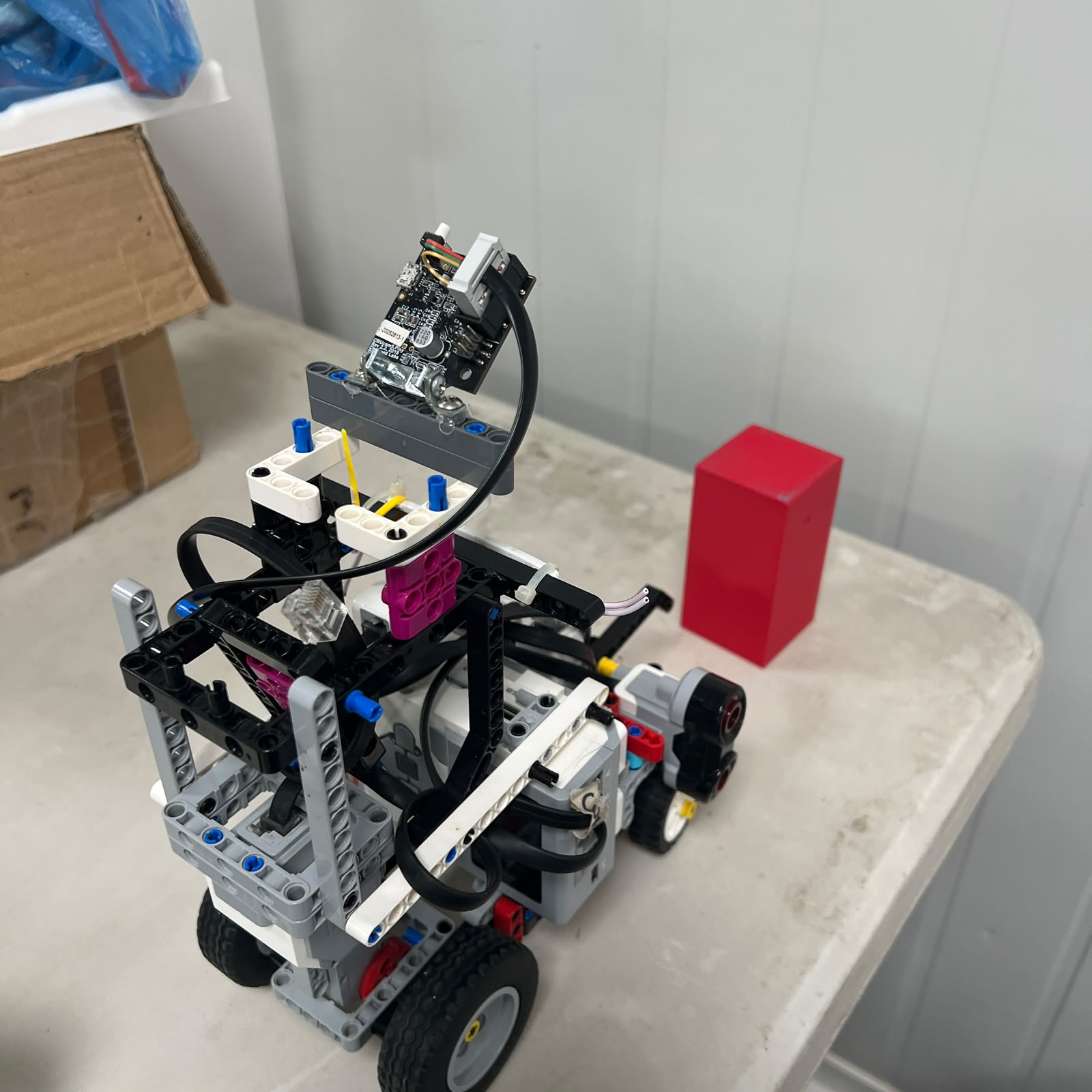 Figure 1.18. Red obstacle used by Pixy2.1 to identify a required pass-right maneuver.
A valid Red detection provides the obstacle identity.
The complete navigation process must still consider:
```text
target relevance
current vehicle position
wall geometry
current maneuver state
vehicle speed
```
before Motor B receives its final steering request.
---
# 1.24 Green Visual Detection
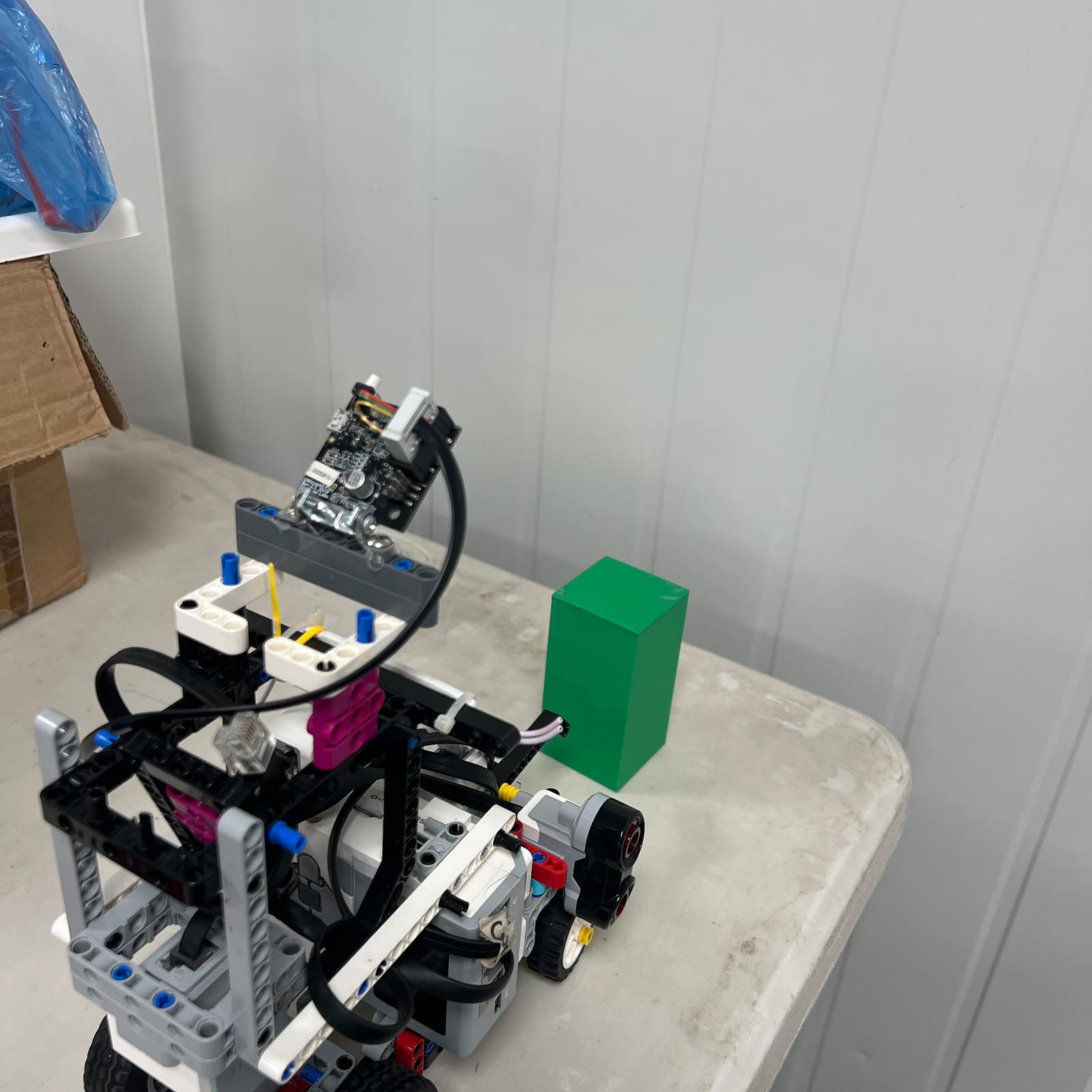 Figure 1.19. Green obstacle used by Pixy2.1 to identify a required pass-left maneuver.
The Green target creates the opposite passing objective.
However, left and right maneuver calibration should be validated separately because real steering geometry does not have to be perfectly symmetrical.
---
# 1.25 Parking Visual Reference
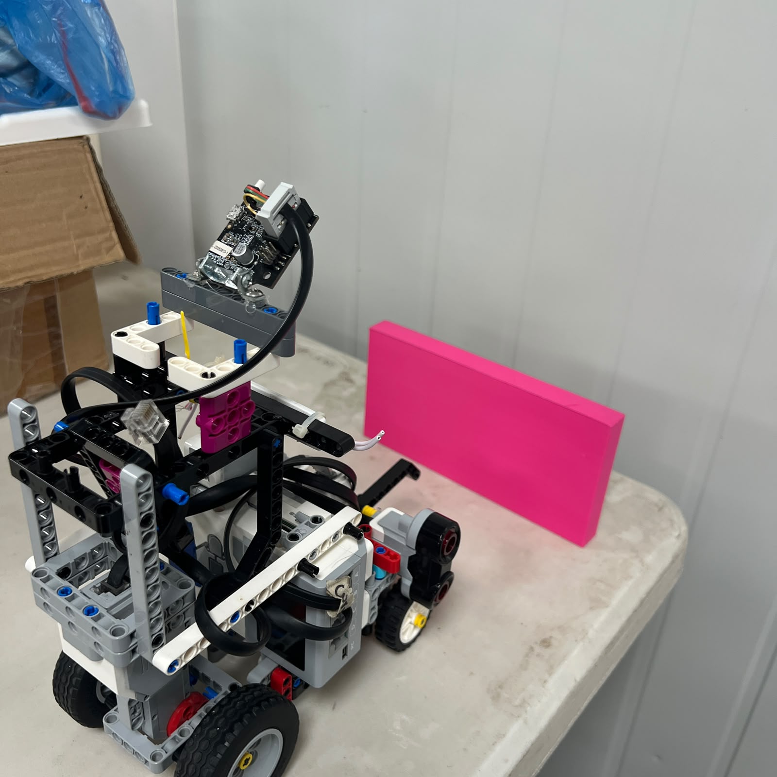 Figure 1.20. Signature 1 is reserved for the visual parking reference in the current Pixy configuration.
A parking-signature detection should not automatically mean:
```text
park immediately
```
A stronger parking condition can combine:
```text
visual parking reference
course progression
encoder displacement
ultrasonic geometry
```
The final parking strategy remains under development.
---
# 1.26 Pixy and Ultrasonic Sensor Fusion
During Obstacles:
```text
Pixy
→ identifies target and image position
```
while:
```text
S2 / S3
→ describe surrounding lateral geometry
```
This creates complementary sensing.
For example, Pixy may determine:
```text
GREEN
→ pass LEFT
```
but the left ultrasonic can still indicate whether the vehicle is approaching an unsafe boundary.
The EV3 therefore remains responsible for balancing:
```text
obstacle objective
```
with:
```text
wall safety
```
rather than allowing one sensor to control Motor B directly.
---
# 1.27 Why Pixy Does Not Replace Ultrasonics
A camera can identify the target but does not directly provide the same type of metric wall-distance information as the ultrasonic sensors.
Likewise, ultrasonic sensors can provide physical distance information but cannot distinguish:
```text
red
```
from:
```text
green
```
The systems solve different perception problems.
```text
Pixy
→ identity + image localization
Ultrasonics
→ physical lateral geometry
```
This is why both remain active during Obstacles.
---
# 1.28 Why the Gyro Is Removed During Obstacles
The Gyro Sensor would still provide useful rotational information, but the obstacle challenge has a more fundamental requirement:
```text
identify pillar color
```
The available S1 connection is therefore assigned to the vision sensor.
The design trade-off is:
```text
remove direct gyro heading
```
to gain:
```text
visual obstacle identity
+
visual location
```
The two lateral ultrasonic sensors remain available to support track-relative recovery after obstacle maneuvers.
---
# 1.29 Why There Is No Front Ultrasonic Sensor
Earlier Piolín configurations used or considered an additional frontal ultrasonic sensor.
The current robot does not include one.
The final sensor allocation is:
```text
S1
→ Gyro or Pixy2.1
S2
→ Left US
S3
→ Right US
S4
→ Color
```
A permanent frontal ultrasonic sensor would require replacing one of these information sources or adding an external interface.
The current design instead prioritizes:
```text
two-sided lateral geometry
floor-state sensing
round-specific orientation or vision
```
This is a deliberate systems trade-off.
---
# 1.30 Why HuskyLens and Arduino Nano Are Not Current
Earlier vision development used:
```text
HuskyLens
↓
Arduino Nano
↓
EV3
```
The current architecture uses:
```text
Pixy2.1
↓
S1
↓
EV3
```
The Arduino Nano and HuskyLens therefore belong to Piolín's development history, not the current competition configuration.
Removing the intermediate electronics reduced:
```text
hardware count
wiring
communication layers
firmware dependencies
power dependencies
```
The historical system remains valuable as evidence of engineering iteration, but it should not appear in current reconstruction instructions.
---
# 1.31 Wiring — Open Challenge
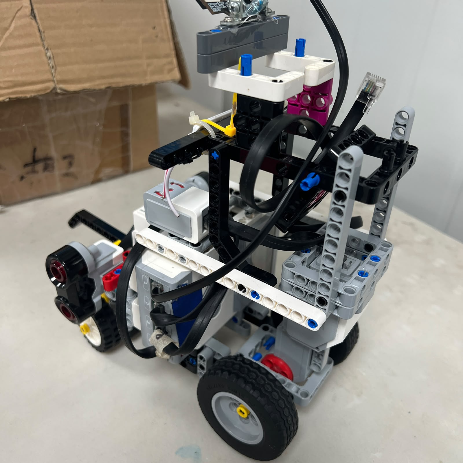 Figure 1.21. Current Open wiring configuration with Gyro on S1.
The complete Open mapping is:
```text
MOTORS
A → Large Motor
B → Medium Motor
SENSORS
S1 → Gyro
S2 → Left Ultrasonic
S3 → Right Ultrasonic
S4 → Color Sensor
```
This physical mapping must match the Open software configuration.
---
# 1.32 Wiring — Obstacle Challenge
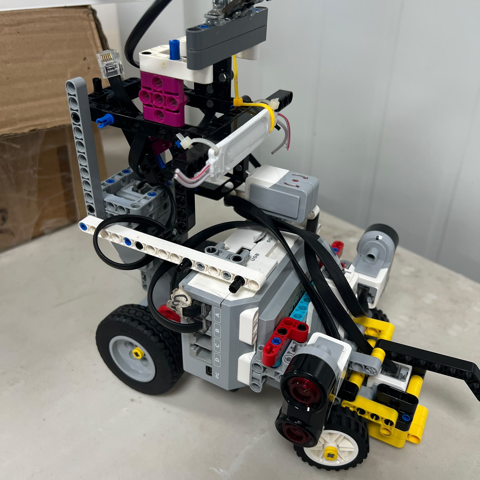 Figure 1.22. Current Obstacle wiring configuration with Pixy2.1 on S1.
The Obstacle mapping is:
```text
MOTORS
A → Large Motor
B → Medium Motor
SENSORS
S1 → Pixy2.1
S2 → Left Ultrasonic
S3 → Right Ultrasonic
S4 → Color Sensor
```
Only S1 changes between the two configurations.
---
# 1.33 Round Comparison
| System | Open Challenge | Obstacle Challenge |
| :--- | :--- | :--- |
| Battery | EV3 45501 | EV3 45501 |
| Controller | EV3 | EV3 |
| Motor A | Large Motor | Large Motor |
| Motor B | Medium Motor | Medium Motor |
| S1 | Gyro | Pixy2.1 |
| S2 | Left Ultrasonic | Left Ultrasonic |
| S3 | Right Ultrasonic | Right Ultrasonic |
| S4 | Color Sensor | Color Sensor |
| Front Ultrasonic | No | No |
| Arduino Nano | No | No |
| HuskyLens | No | No |
This comparison demonstrates how little of the hardware must change between rounds.
---
# 1.34 Software Environment by Round
The sensor architecture also affects the software environment.
The current Open development path uses:
```text
Pybricks MicroPython
```
with the gyro directly integrated into the EV3 Open controller.
The current obstacle development path uses:
```text
ev3dev2
+
SMBus / I2C communication
```
for Pixy2.1 integration.
These software environments should remain separated by round rather than mixed unnecessarily in one program.
The physical S1 device and the software used to access it must always correspond.
---
# 1.35 Startup Verification
Before autonomous movement begins, the current hardware configuration should be verified.
For Open:
```text
S1 Gyro responding?
S2 Left US responding?
S3 Right US responding?
S4 Color responding?
Motor A responding?
Motor B responding?
```
For Obstacles:
```text
S1 Pixy responding?
S2 Left US responding?
S3 Right US responding?
S4 Color responding?
Motor A responding?
Motor B responding?
```
A missing sensor should preferably be detected before the robot begins driving.
---
# 1.36 Sensor Roles vs. Motor Roles
A useful system distinction is:
```text
SENSORS
→ observe state
```
```text
EV3
→ decides
```
```text
MOTORS
→ create physical response
```
For example:
```text
S2 reports geometry
↓
EV3 calculates correction
↓
Motor B changes steering
↓
vehicle moves
↓
S2 observes new geometry
```
The same feedback principle applies to the gyro and Pixy systems.
No sensor directly controls the motors.
---
# 1.37 Sensor Redundancy and Complementarity
Piolín does not attempt to make every sensor measure the same physical quantity.
Instead, the architecture emphasizes complementary information.
### Open
```text
Gyro
→ heading
Ultrasonics
→ lateral geometry
Color
→ course state
```
### Obstacles
```text
Pixy
→ visual identity / position
Ultrasonics
→ lateral geometry
Color
→ course state
```
This reduces the chance that one sensor is asked to solve a problem it does not measure well.
---
# 1.38 Physical Sensor Placement Matters
Sensor calibration only remains valid if physical placement remains consistent.
Relevant variables include:
```text
ultrasonic orientation
ultrasonic mounting position
Color Sensor height
Color Sensor casing position
Gyro orientation
Pixy pitch
Pixy yaw
Pixy lateral placement
```
A software threshold should therefore not be changed before verifying that the sensor itself has not moved.
This principle is particularly important after:
```text
transport
chassis changes
sensor remounting
competition-round conversion
```
---
# 1.39 Sensor Failure Diagnosis
| Symptom | First Areas to Check |
| :--- | :--- |
| Open heading incorrect | Gyro orientation, reset, S1, software |
| Left wall value incorrect | S2, left sensor mount, cable |
| Right wall value incorrect | S3, right sensor mount, cable |
| Inner/outer logic appears inverted | Verify direction state, not S2/S3 wiring first |
| Color never detected | S4, casing, height, classification |
| Blue/Orange reversed logically | Initial direction mapping |
| Red causes wrong maneuver | Pixy signature mapping or steering interpretation |
| Green causes wrong maneuver | Pixy signature mapping or steering interpretation |
| Pixy detects wrong target | Signature calibration / target selection |
| Pixy unavailable | S1 connection / obstacle software |
| Sensor behavior changed after rebuild | Verify mechanical sensor placement |
A sensor-related navigation failure should be traced through:
```text
physical target
↓
sensor
↓
raw measurement
↓
software interpretation
↓
navigation decision
```
before controller tuning begins.
---
# 1.40 Current vs. Legacy Architecture
The current architecture should always be distinguished from earlier Piolín configurations.
### Current Open
```text
S1 Gyro
S2 Left US
S3 Right US
S4 Color
```
### Current Obstacles
```text
S1 Pixy2.1
S2 Left US
S3 Right US
S4 Color
```
### Legacy or experimental hardware
```text
HuskyLens
Arduino Nano
front ultrasonic
previous Pixy configurations
different ultrasonic orientations
```
Legacy systems demonstrate development history but must not be presented as the current reconstruction configuration.
---
# 1.41 Values Intentionally Not Claimed as Final
The following should only be published after current V4 testing or measurement:
```text
final ultrasonic target distance
final wall safety thresholds
final ultrasonic filtering constants
final gyro drift
final gyro corner angle
final RGB thresholds
final Color Sensor event thresholds
Pixy mounting height
Pixy mounting angle
Pixy horizontal target coordinate
minimum Pixy block size
maximum Pixy block size
final target-lock duration
final visual confirmation count
final obstacle reaction distance
final parking visual threshold
complete system current draw
```
The architecture can be documented accurately without inventing these values.
---
# 1.42 Current Power and Sensor Architecture
The complete architecture can be summarized as:
```text
BATTERY 45501
│
▼
EV3
│
┌─────────────────┼──────────────────┐
│ │ │
▼ ▼ ▼
Motor A Motor B SENSOR PORTS
│ │ │
▼ ▼ ┌─────────┼─────────┐
Propulsion Steering S1 S2/S3 S4
│ │ │
┌────────────┴────┐ │ │
│ │ │ │
OPEN OBSTACLES │ │
│ │ │ │
▼ ▼ ▼ ▼
Gyro Pixy Left/Right Color
Ultrasonic
```
The most important configuration rules are:
```text
A = PROPULSION
B = STEERING
S2 = LEFT
S3 = RIGHT
S4 = COLOR
S1 OPEN = GYRO
S1 OBSTACLES = PIXY2.1
```
These mappings should remain consistent across:
```text
hardware
software
testing
documentation
reproduction instructions
```
---
# 1.43 Final Engineering Assessment
Piolín's current power and sensor configuration is built around the idea that the robot should use the **smallest practical set of sensors that provides the information required by each challenge**.
Three sensor roles remain constant:
```text
S2
→ left-side geometry
S3
→ right-side geometry
S4
→ floor/course state
```
The specialized S1 information changes:
```text
OPEN
→ heading through Gyro
```
```text
OBSTACLES
→ visual perception through Pixy2.1
```
This allows Piolín to use one common mechanical and electrical vehicle platform while adapting its perception system to two fundamentally different navigation problems.
The same EV3 Brick and EV3 Rechargeable Battery remain central to both configurations. Motor A continues providing propulsion, Motor B continues providing steering, and the lateral ultrasonic and floor-sensing systems remain physically unchanged.
The current architecture also reflects several engineering decisions made during development:
```text
remove the permanent front ultrasonic
remove HuskyLens from the final architecture
remove Arduino Nano from the final architecture
restore gyro as an Open-specific sensor
use Pixy2.1 directly as the Obstacle-specific vision sensor
keep S2 and S3 permanently mapped to LEFT and RIGHT
```
These decisions reduce unnecessary communication and hardware layers while preserving the sensing capabilities needed for each competition round.
The final systems principle is therefore:
> **Piolín assigns each sensor a specific physical responsibility, keeps the permanent sensor geometry stable, and changes only the specialized S1 perception device when the information requirements of the competition round change.**
---
### [← Back to PiolínTech Main README](../../README.md)