# 3. Wiring and Port Configuration
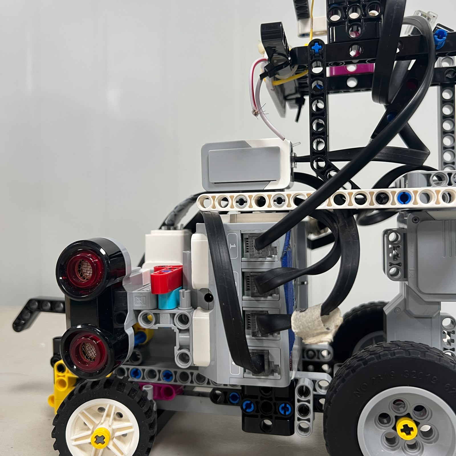 Figure 3.1. Piolín uses the four EV3 sensor ports with a fixed S2/S3/S4 mapping and a round-specific device on S1.
Piolín uses the LEGO Mindstorms EV3 Brick as the central connection point for its motors, sensors, and power system. The wiring architecture was deliberately simplified so that most connections remain unchanged between the **Open Challenge** and the **Obstacle Challenge**.
The permanent port assignments are:
```text
MOTOR A
→ propulsion
MOTOR B
→ steering
S2
→ LEFT Ultrasonic Sensor
S3
→ RIGHT Ultrasonic Sensor
S4
→ Color Sensor
```
Only Sensor Port S1 changes between competition rounds:
```text
OPEN
S1 → EV3 Gyro Sensor
```
```text
OBSTACLES
S1 → Pixy2.1
```
The Gyro Sensor and Pixy2.1 are **never installed simultaneously** in the current Piolín architecture.
This is the most important wiring rule for reproducing the current robot.
---
## 3.1 Complete Port Map
The current electrical mapping can be summarized as:
| EV3 Port | Open Challenge | Obstacle Challenge | Physical Role |
| :---: | :--- | :--- | :--- |
| A | EV3 Large Motor | EV3 Large Motor | Rear propulsion |
| B | EV3 Medium Motor | EV3 Medium Motor | Front steering |
| C | Unused | Unused | — |
| D | Unused | Unused | — |
| S1 | EV3 Gyro Sensor | Pixy2.1 | Round-specific perception |
| S2 | Left Ultrasonic Sensor | Left Ultrasonic Sensor | Left lateral geometry |
| S3 | Right Ultrasonic Sensor | Right Ultrasonic Sensor | Right lateral geometry |
| S4 | EV3 Color Sensor | EV3 Color Sensor | Floor/course-state sensing |
The fixed mapping should be preserved in both hardware and software.
```text
A = DRIVE
B = STEERING
S2 = LEFT
S3 = RIGHT
S4 = COLOR
```
This convention should never be inverted only because Piolín changes from clockwise to counterclockwise navigation.
---
# 3.2 Motor Wiring
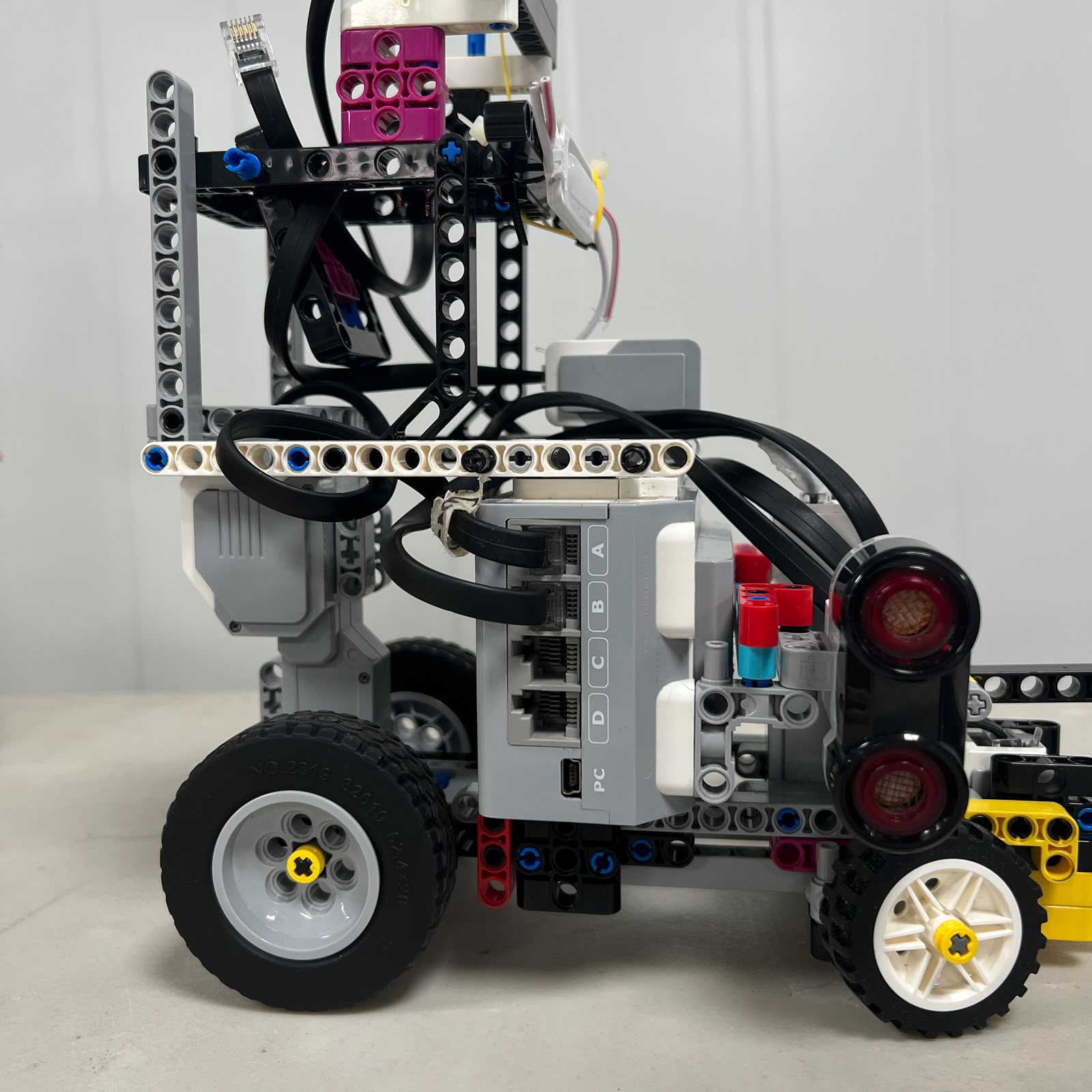 Figure 3.2. Piolín uses only Motor Ports A and B.
Piolín uses two LEGO Mindstorms EV3 motors.
### Port A — propulsion
```text
EV3 Port A
↓
EV3 Large Motor
↓
rear drivetrain
↓
rear wheels
```
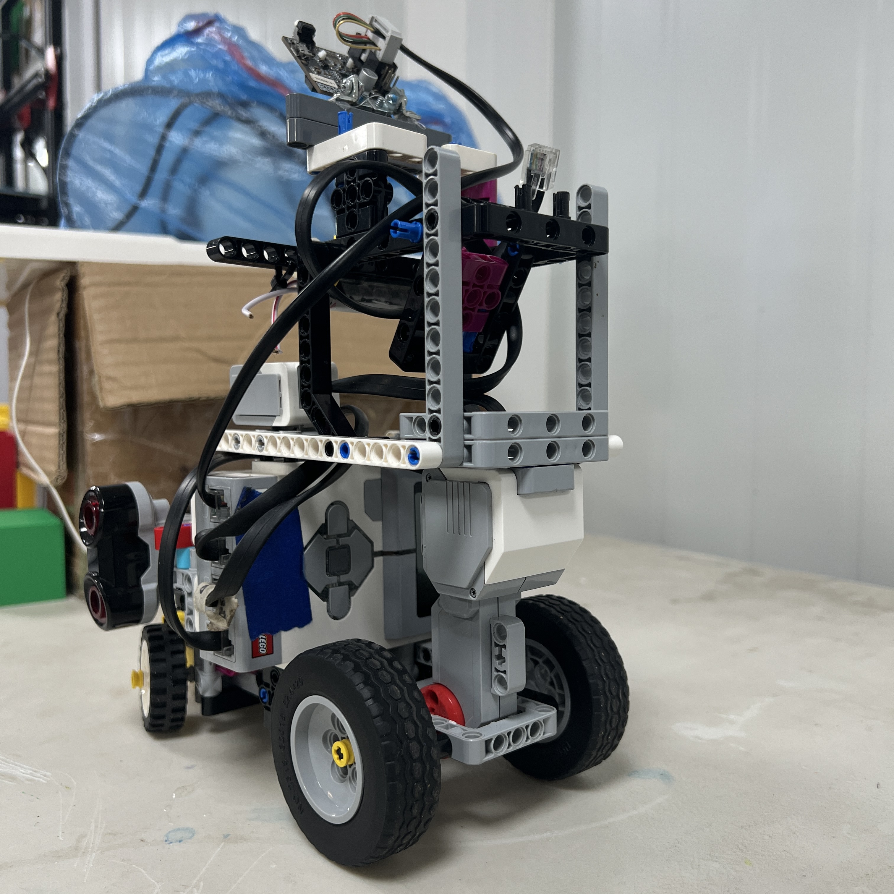 Figure 3.3. Motor A is the only propulsion actuator in the current vehicle.
The Large Motor drives the rear wheels and is responsible for:
```text
forward motion
reverse motion
approach speed
course travel
parking displacement
```
### Port B — steering
```text
EV3 Port B
↓
EV3 Medium Motor
↓
Ackermann-style steering linkage
↓
front wheels
```
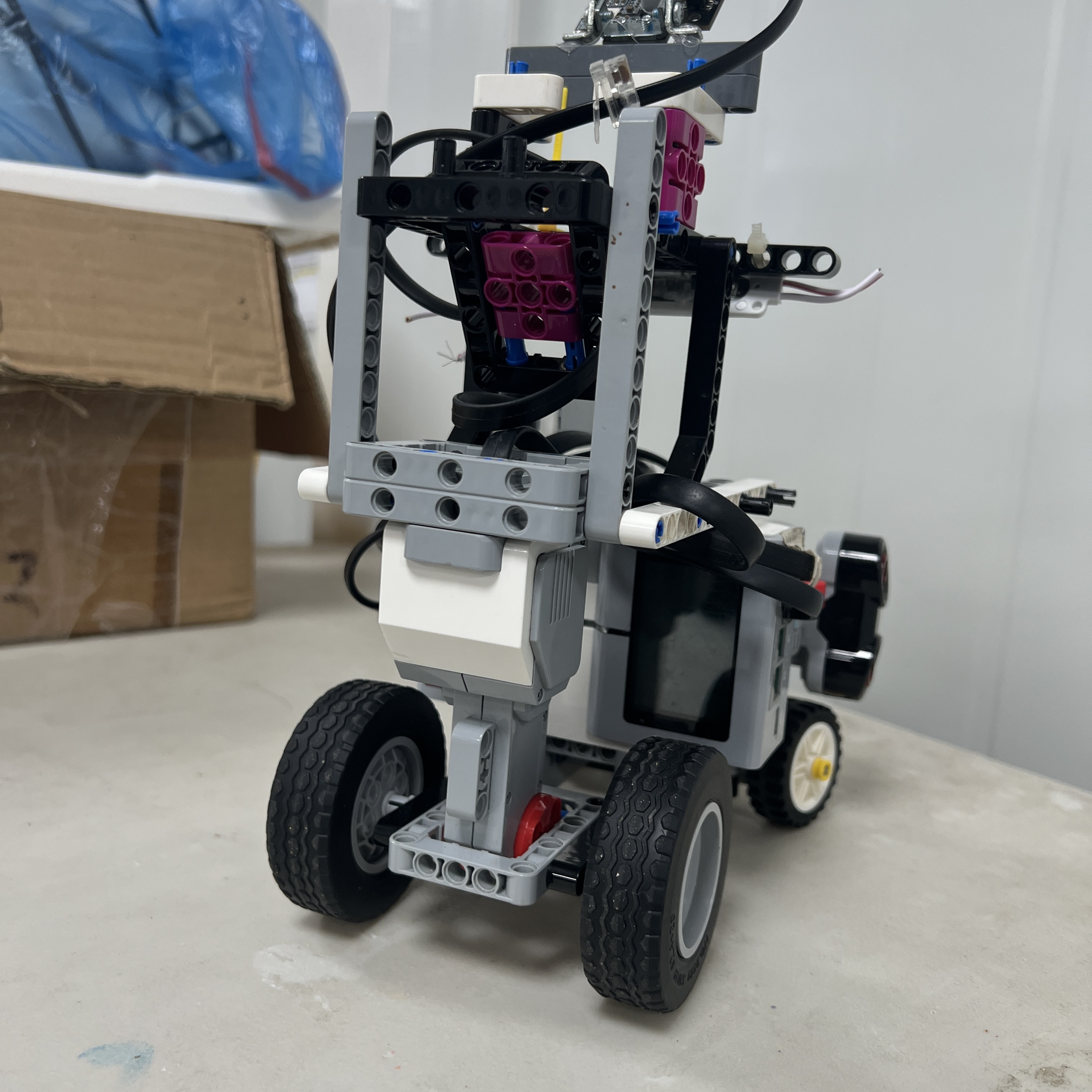 Figure 3.4. Motor B is dedicated to the front steering mechanism.
Ports C and D are not required in the current two-motor architecture.
This wiring is identical for both competition rounds.
---
# 3.3 Permanent Sensor Wiring
Three sensor connections remain unchanged regardless of round:
```text
S2 → LEFT Ultrasonic
S3 → RIGHT Ultrasonic
S4 → Color Sensor
```
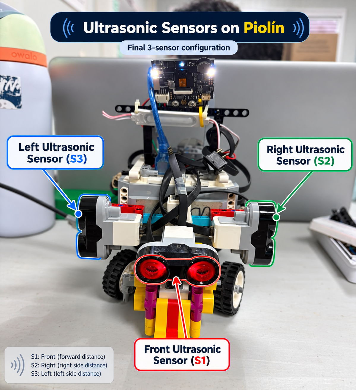 Figure 3.5. Permanent physical ultrasonic mapping: S2 is LEFT and S3 is RIGHT.
The physical identity must remain constant.
The software may later interpret one sensor as:
```text
INNER
```
and the other as:
```text
OUTER
```
depending on course direction, but the electrical port assignment does not change.
This avoids a common source of navigation errors where the software assumes the opposite side from the actual connected sensor.
---
# 3.4 Left Ultrasonic — S2
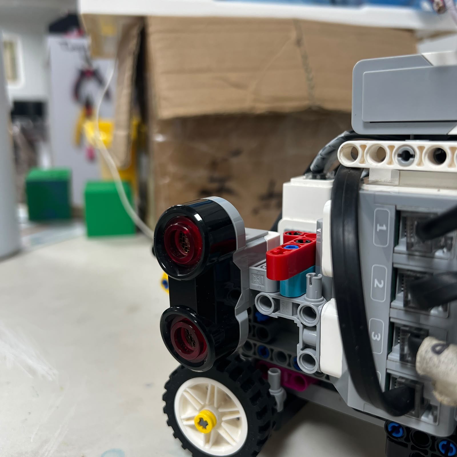 Figure 3.6. Left lateral EV3 Ultrasonic Sensor connected permanently to S2.
The S2 cable should connect:
```text
LEFT Ultrasonic Sensor
↓
EV3 Sensor Port S2
```
Its physical role remains:
```text
LEFT-SIDE GEOMETRY
```
in both rounds.
During counterclockwise Open navigation it becomes the logical inner sensor.
During clockwise navigation it becomes the logical outer sensor.
The physical connection itself never changes.
---
# 3.5 Right Ultrasonic — S3
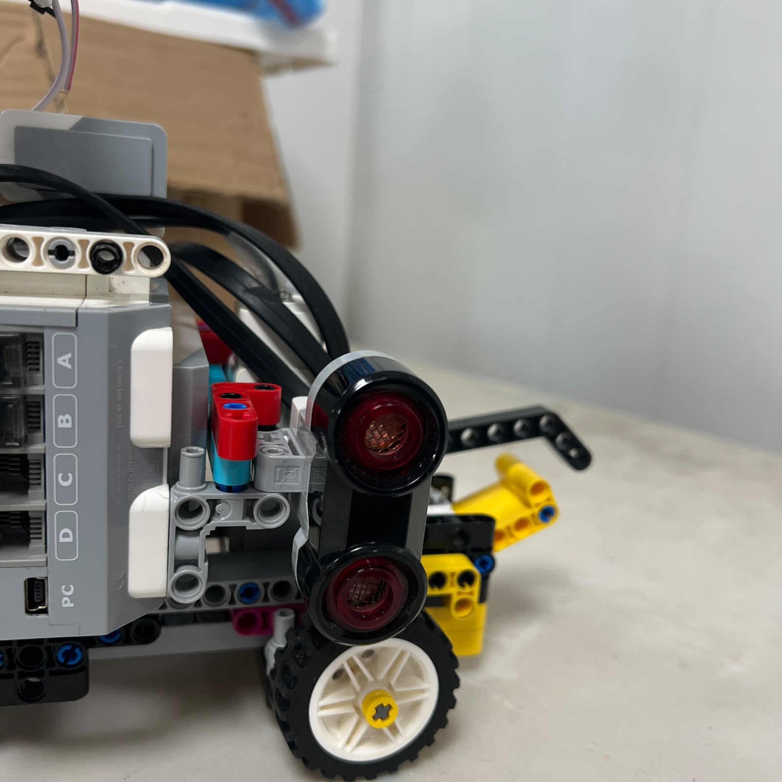 Figure 3.7. Right lateral EV3 Ultrasonic Sensor connected permanently to S3.
The S3 connection is:
```text
RIGHT Ultrasonic Sensor
↓
EV3 Sensor Port S3
```
Its permanent physical responsibility is:
```text
RIGHT-SIDE GEOMETRY
```
As with S2, only its logical inner/outer interpretation changes according to course direction.
---
# 3.6 Color Sensor — S4
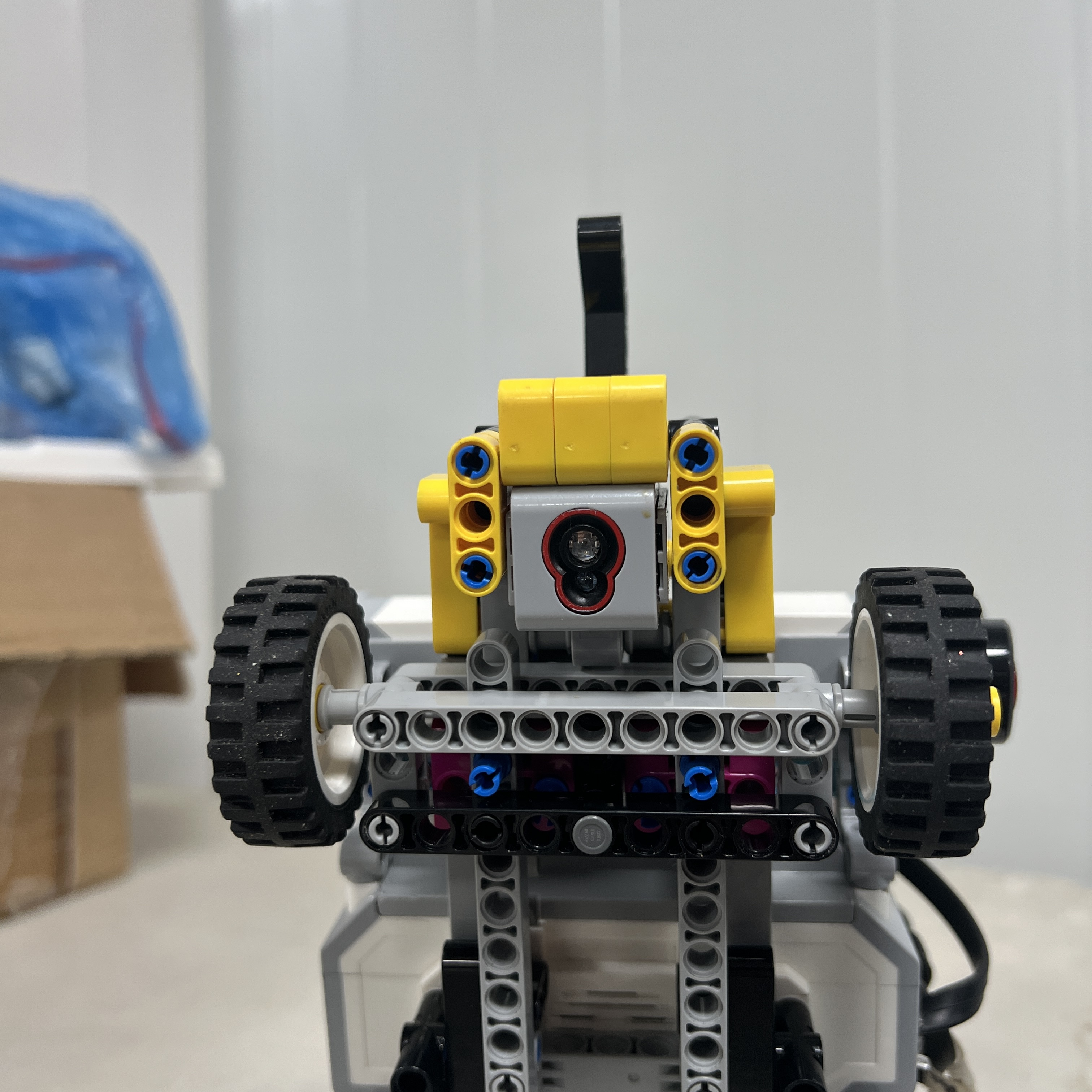 Figure 3.8. The downward-facing Color Sensor remains permanently connected to Sensor Port S4.
The Color Sensor connection is:
```text
EV3 Color Sensor
↓
Sensor Port S4
```
Its role remains constant in both rounds:
```text
floor detection
Blue / Orange landmarks
course-state information
progress support
```
The sensor is installed with its current light-isolation casing.
The casing does not create a separate electrical connection, but it is part of the calibrated S4 installation and should remain mechanically secure.
---
# 3.7 Open Challenge Wiring
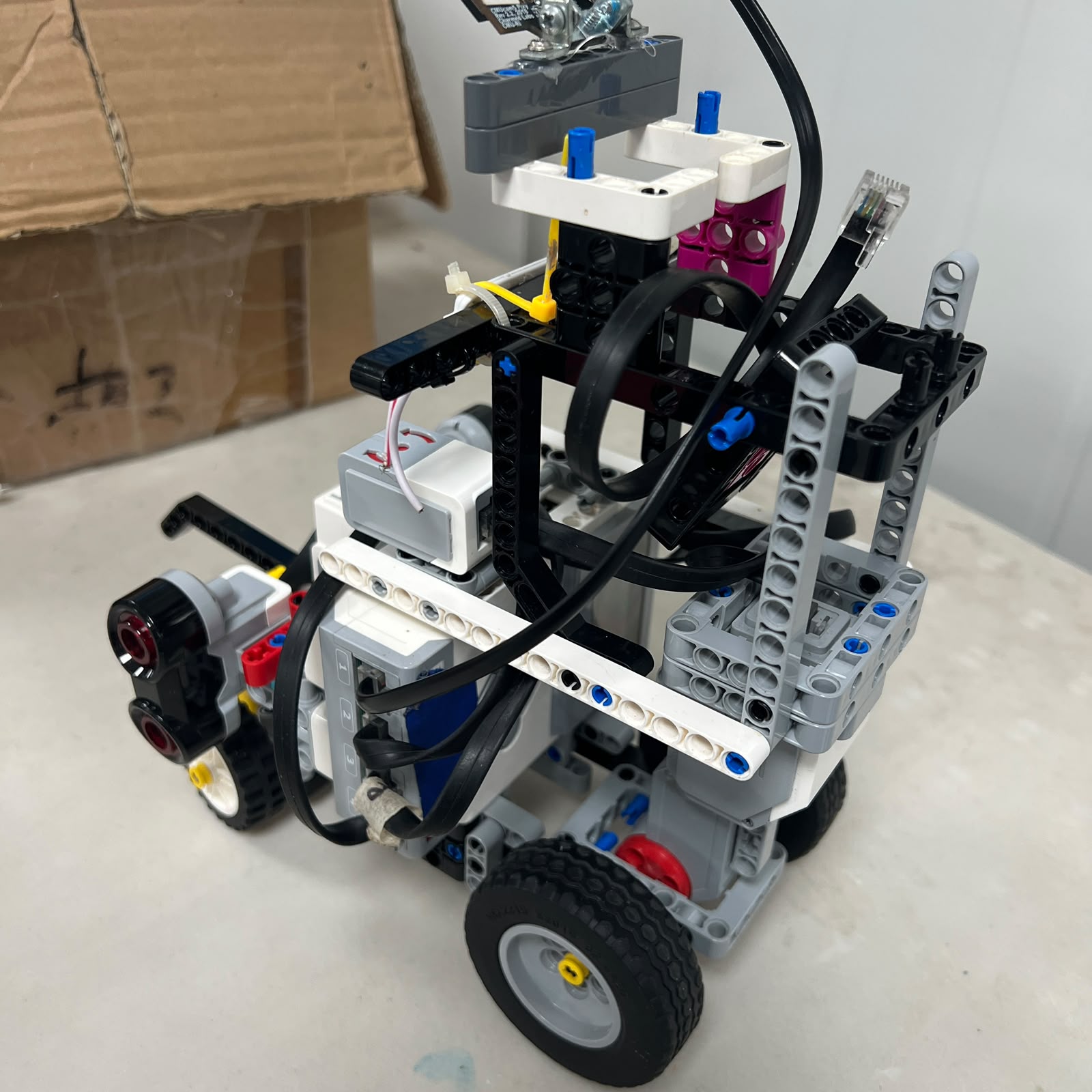 Figure 3.9. Complete current wiring configuration for the Open Challenge.
For the Open Challenge, the complete wiring is:
```text
EV3 BRICK
MOTOR PORTS SENSOR PORTS
A → Large Motor S1 → Gyro
B → Medium Motor S2 → Left US
C → unused S3 → Right US
D → unused S4 → Color
```
The corresponding functional architecture is:
```text
EV3
│
┌─────────┼─────────┐
│ │
▼ ▼
MOTORS SENSORS
│ │
┌────┴────┐ ┌──────┼──────┬──────┐
│ │ │ │ │ │
▼ ▼ ▼ ▼ ▼ ▼
A B S1 S2 S3 S4
│ │ │ │ │ │
Large Medium Gyro Left Right Color
Drive Steering US US
```
This configuration is used only for the Open Challenge.
---
# 3.8 Gyro Connection — Open S1
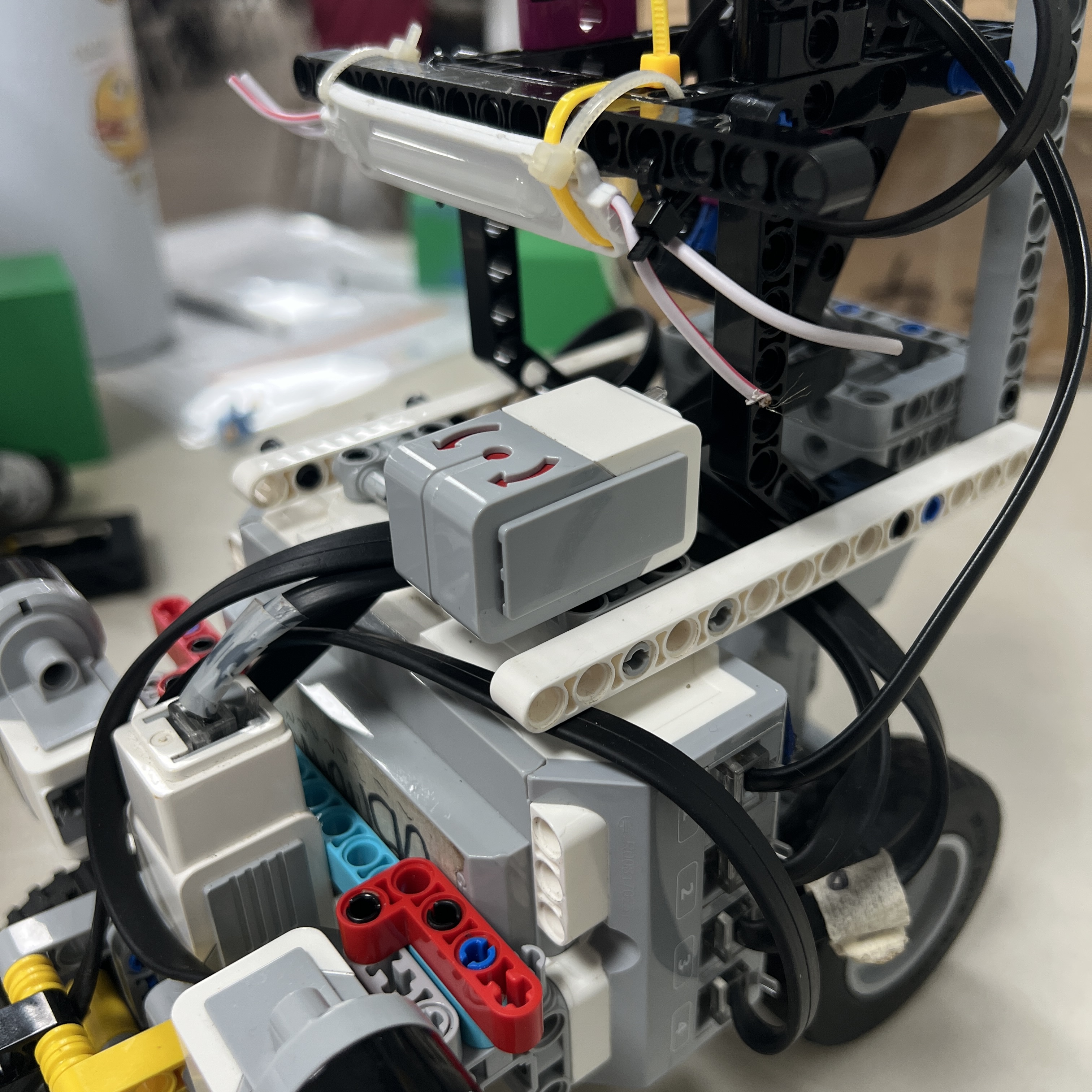 Figure 3.10. S1 is occupied by the EV3 Gyro Sensor during Open.
The Open S1 path is:
```text
EV3 Gyro Sensor
↓
EV3 Sensor Port S1
```
The gyro provides:
```text
heading reference
rotation information
straight-line stabilization support
corner-progress information
```
Its physical orientation relative to the robot should remain unchanged after calibration.
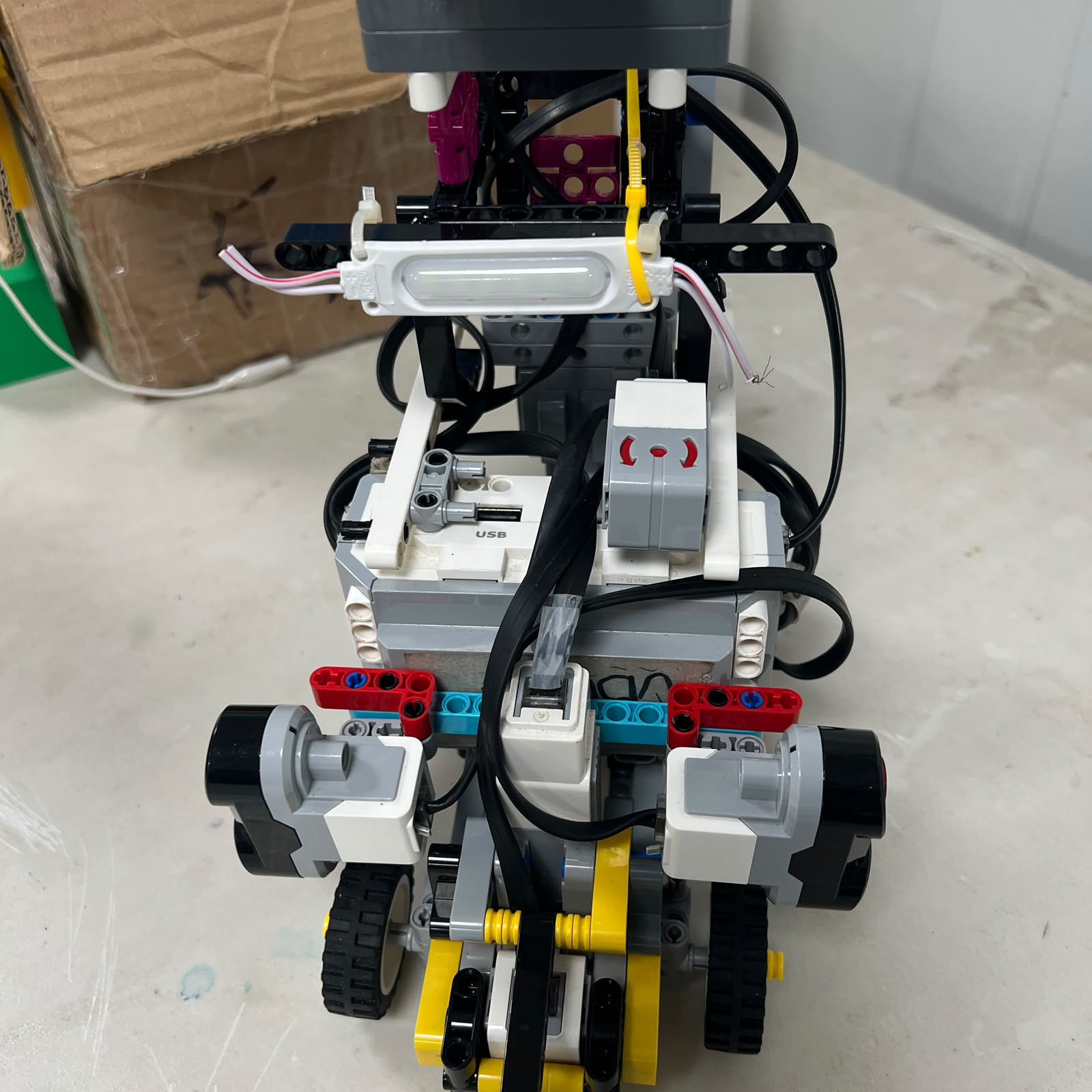 Figure 3.11. The gyro orientation is part of the reproducible Open installation.
A correctly connected gyro that has been physically rotated into a different orientation can still produce incorrect navigation behavior.
Therefore wiring reproduction must include both:
```text
correct port
+
correct physical installation
```
---
# 3.9 Obstacle Challenge Wiring
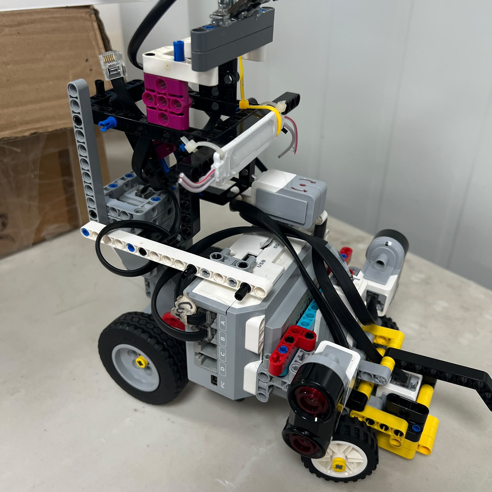 Figure 3.12. Complete current wiring configuration for the Obstacle Challenge.
For the Obstacle Challenge:
```text
EV3 BRICK
MOTOR PORTS SENSOR PORTS
A → Large Motor S1 → Pixy2.1
B → Medium Motor S2 → Left US
C → unused S3 → Right US
D → unused S4 → Color
```
The functional architecture becomes:
```text
EV3
│
┌─────────┼─────────┐
│ │
▼ ▼
MOTORS SENSORS
│ │
┌────┴────┐ ┌──────┼──────┬──────┐
│ │ │ │ │ │
▼ ▼ ▼ ▼ ▼ ▼
A B S1 S2 S3 S4
│ │ │ │ │ │
Large Medium Pixy Left Right Color
Drive Steering 2.1 US US
```
The Gyro Sensor must not remain connected in this configuration.
---
# 3.10 Pixy2.1 Connection — Obstacle S1
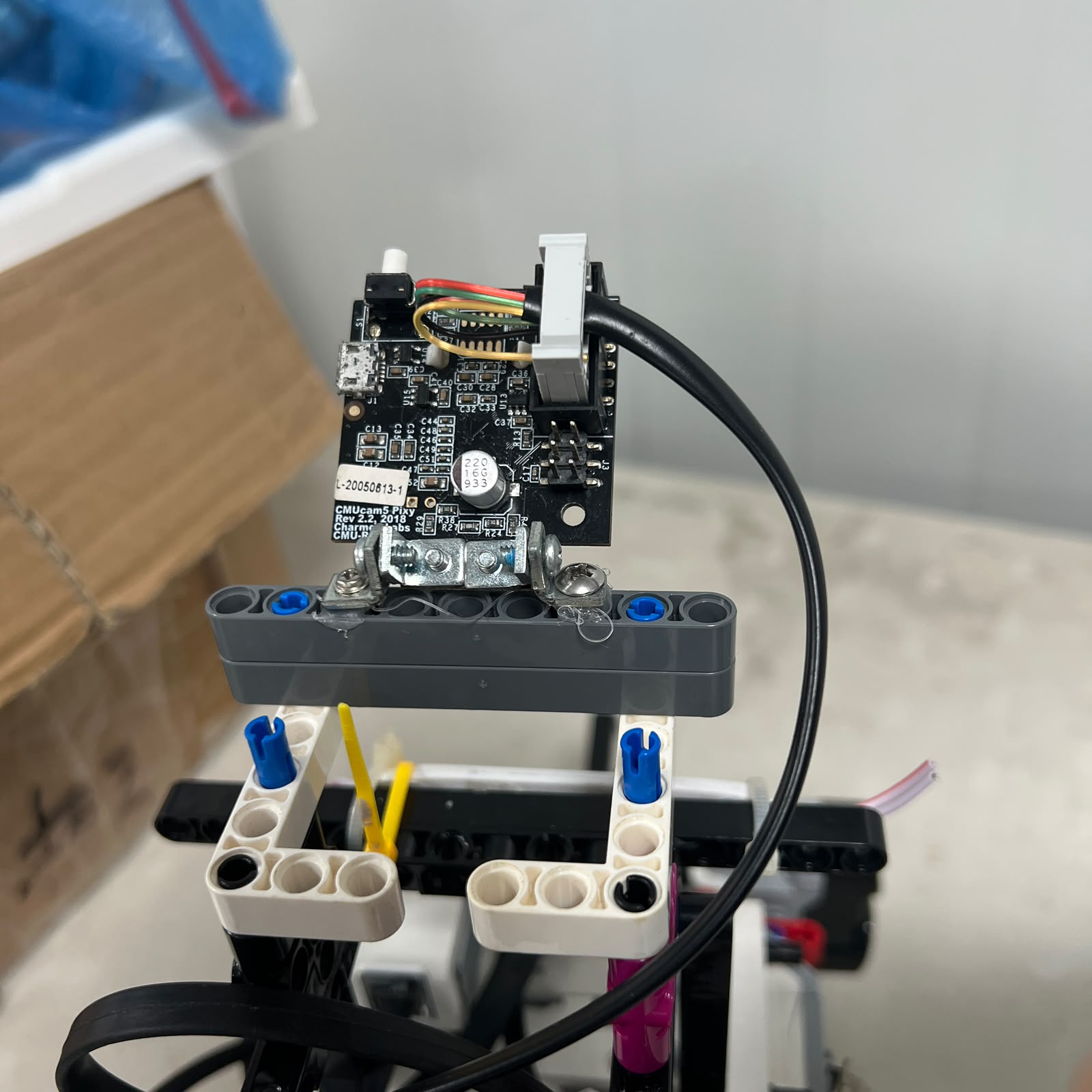 Figure 3.13. Pixy2.1 occupies Sensor Port S1 during the Obstacle Challenge.
The current vision connection is:
```text
Pixy2.1
↓
Pixy connection cable
↓
EV3 Sensor Port S1
```
The same physical interface is used for the current communication and power connection to the camera during the Obstacle configuration.
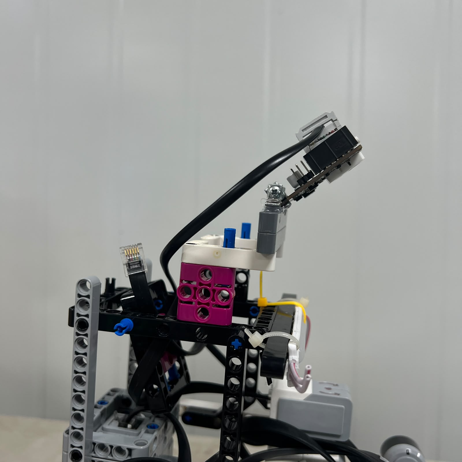 Figure 3.14. Current connection cable used in Piolín's direct Pixy2.1 integration.
The current software communicates with Pixy2.1 through an I2C/SMBus-style interface.
The repository should not invent a separate internal wire or connector pinout unless that pinout has been physically verified from the actual cable.
For reproduction, the authoritative physical reference is the actual connection shown in the V4 photographs.
---
# 3.11 Pixy2.1 Physical Installation
The current Pixy2.1 also includes a **3D-printed casing**.
The casing does not change the EV3 port mapping:
```text
Pixy2.1
→ still S1
```
but it is part of the current mechanical camera installation.
The casing should remain installed because it contributes to:
```text
camera protection
mounting repeatability
physical integration
more controlled optical conditions
```
The exact camera orientation and casing position should be preserved when comparing calibrated visual behavior.
The repository does not currently use a separate image filename specifically for this casing, so no nonexistent image is referenced here.
---
# 3.12 Power Distribution
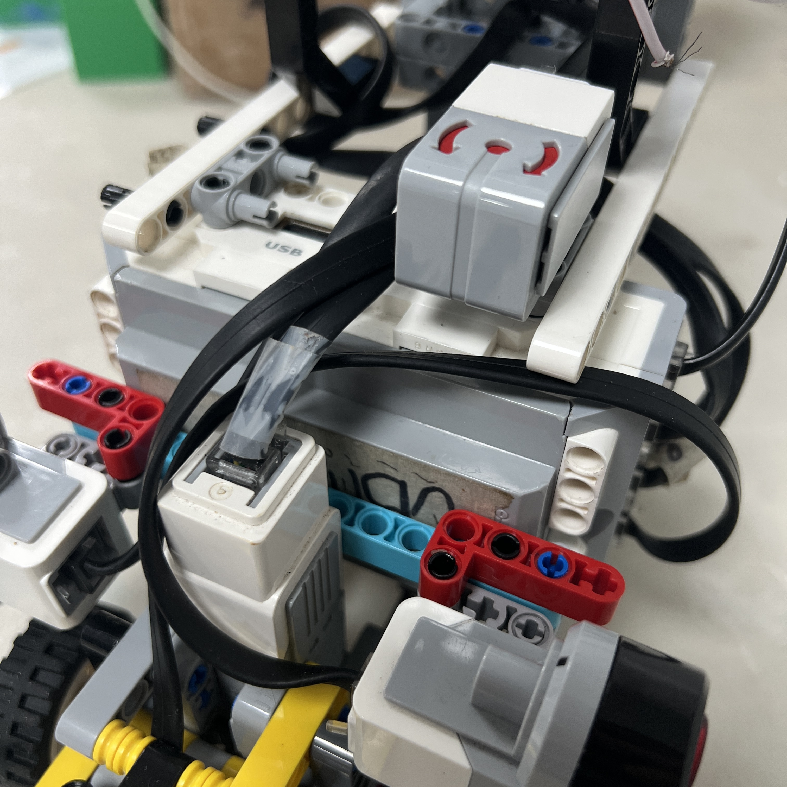 Figure 3.15. The EV3 Rechargeable DC Battery 45501 is the central power source for Piolín.
Piolín uses the LEGO Mindstorms EV3 Rechargeable DC Battery **45501** installed in the EV3 Brick.
The high-level power architecture is:
```text
EV3 Battery 45501
↓
EV3 Brick
│
├── Motor A
├── Motor B
├── S1 device
├── S2 Ultrasonic
├── S3 Ultrasonic
└── S4 Color Sensor
```
The current competition architecture does not use:
```text
external drive battery
separate Pixy battery
Arduino Nano power system
permanent external buck converter
```
During Obstacles, Pixy2.1 operates through the current EV3 S1 connection rather than through a separate external power architecture.
This keeps the competition wiring significantly simpler than earlier prototypes.
---
# 3.13 Round Conversion Procedure
Because the two configurations differ only at S1 and in their corresponding software environment, conversion between rounds should be controlled and simple.
### Open → Obstacles
```text
1. Power down Piolín.
2. Disconnect the Gyro Sensor from S1.
3. Install the Pixy2.1 assembly.
4. Verify the Pixy 3D-printed casing is secure.
5. Connect Pixy2.1 to S1 using the current connection cable.
6. Leave S2, S3, and S4 unchanged.
7. Leave Motors A and B unchanged.
8. Start the Obstacle Challenge software environment.
9. Verify Pixy communication before driving.
```
### Obstacles → Open
```text
1. Power down Piolín.
2. Disconnect Pixy2.1 from S1.
3. Remove the round-specific Pixy assembly as required.
4. Install the EV3 Gyro Sensor.
5. Connect the Gyro Sensor to S1.
6. Verify its physical orientation.
7. Leave S2, S3, and S4 unchanged.
8. Leave Motors A and B unchanged.
9. Start the Open Challenge software.
10. Reset and verify the gyro before driving.
```
The robot should not be rewired while actively running.
---
# 3.14 Why Only S1 Changes
The decision to make S1 modular reduces the number of variables affected when the robot changes competition rounds.
Without this architecture, the team might need to change:
```text
multiple sensors
multiple port assignments
additional controllers
external wiring
```
Instead, Piolín changes:
```text
one specialized sensor
+
its corresponding software interface
```
while preserving:
```text
propulsion
steering
lateral sensing
floor sensing
battery
EV3 controller
```
This makes round conversion easier to verify and reduces the chance of introducing accidental wiring changes.
---
# 3.15 Current Wiring vs. Legacy Wiring
Earlier Piolín prototypes used or tested additional hardware such as:
```text
HuskyLens
Arduino Nano
front ultrasonic sensor
different camera interfaces
different ultrasonic orientations
```
Those connections are **not part of the current V4 competition wiring**.
The current system is:
### Open
```text
A → Large Motor
B → Medium Motor
S1 → Gyro
S2 → Left US
S3 → Right US
S4 → Color
```
### Obstacles
```text
A → Large Motor
B → Medium Motor
S1 → Pixy2.1
S2 → Left US
S3 → Right US
S4 → Color
```
A reproduction of the current robot should not add:
```text
Arduino Nano
HuskyLens
permanent front ultrasonic
```
simply because they appear in older development records.
Those belong to the legacy engineering history.
---
# 3.16 Wiring Verification Before Startup
Before running any autonomous program, the hardware mapping should be verified physically.
### Common checks
```text
A connected to Large Drive Motor?
B connected to Medium Steering Motor?
S2 connected to LEFT Ultrasonic?
S3 connected to RIGHT Ultrasonic?
S4 connected to Color Sensor?
```
### Open-specific checks
```text
Gyro connected to S1?
Pixy disconnected?
Gyro orientation correct?
```
### Obstacle-specific checks
```text
Pixy connected to S1?
Gyro disconnected?
Pixy connection cable secure?
Pixy 3D casing secure?
```
The correct software should only be started after the corresponding hardware configuration has been verified.
---
# 3.17 Software and Wiring Must Agree
A physical connection is only correct when the source code expects the same mapping.
For example:
```text
PHYSICAL
S2 = LEFT
S3 = RIGHT
```
must match:
```text
SOFTWARE
left_sensor = S2
right_sensor = S3
```
If they become swapped in code:
```text
left-wall error
```
can create:
```text
right-side steering response
```
even though every physical cable remains correctly connected.
The same requirement applies to S1.
```text
Open software
→ expects Gyro
```
```text
Obstacle software
→ expects Pixy2.1
```
Running the wrong software environment with the wrong S1 configuration should be treated as a configuration error, not a navigation-tuning problem.
---
# 3.18 Visual Wiring References
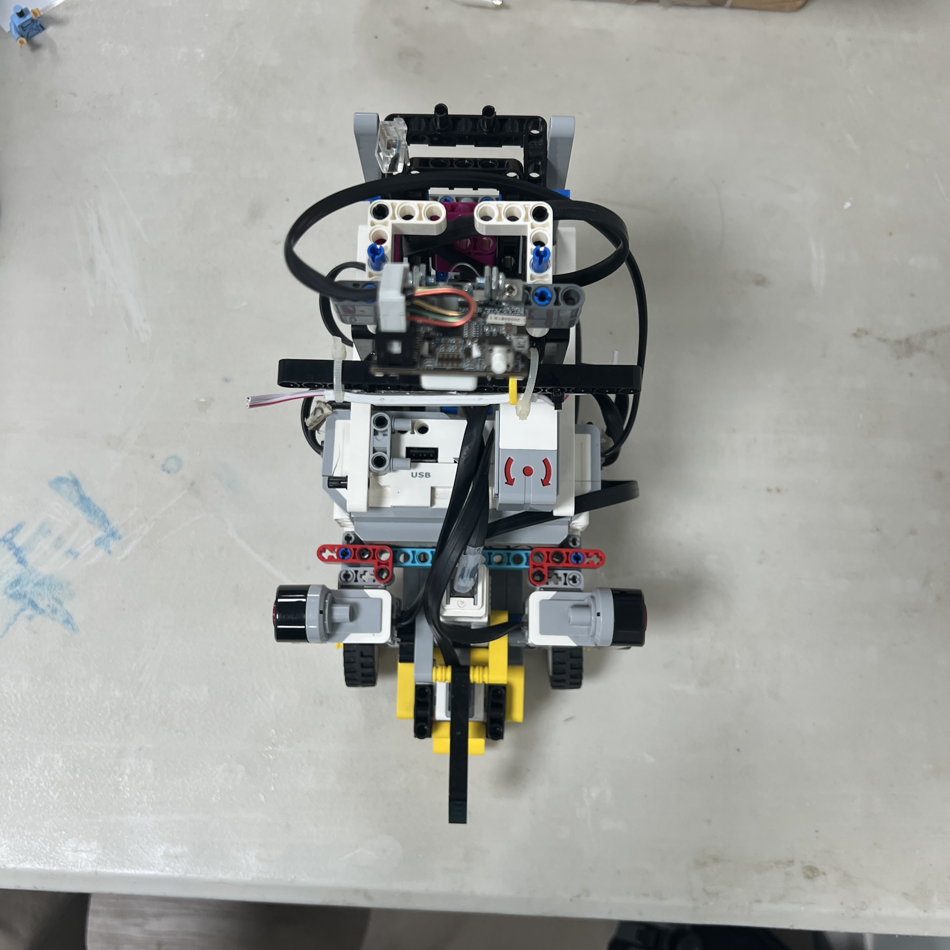 Figure 3.16. Open configuration showing the common vehicle hardware and round-specific Gyro installation.
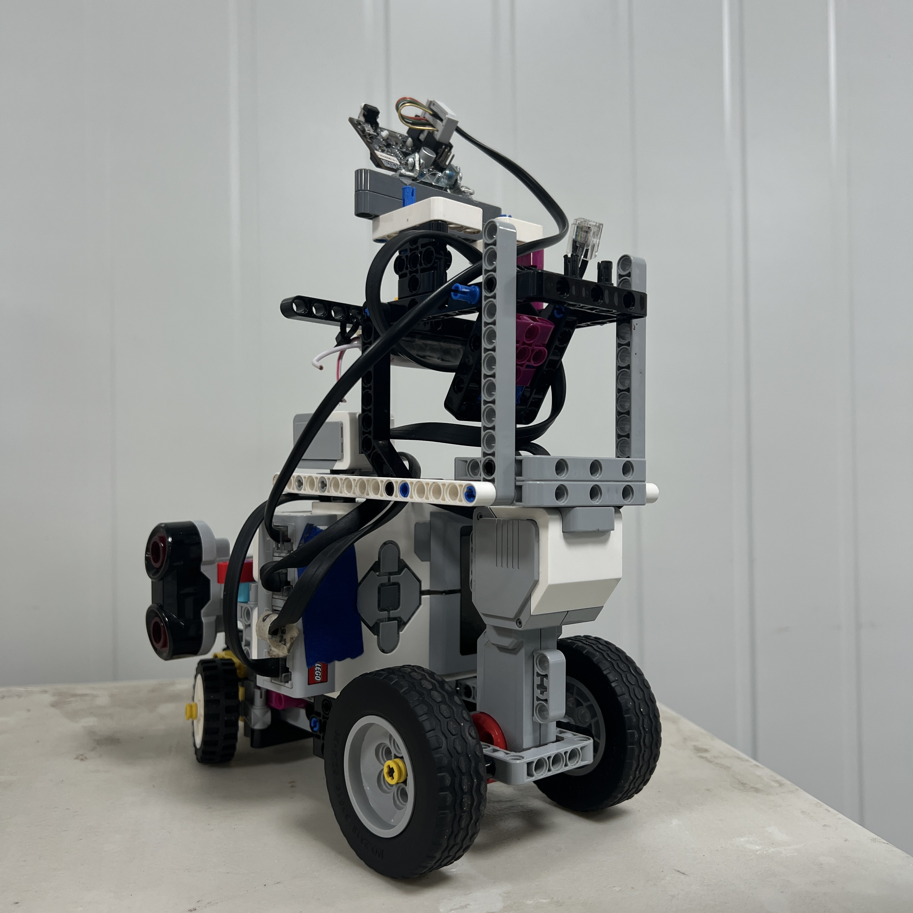 Figure 3.17. Obstacle configuration retains the same drivetrain and permanent sensors while replacing the S1 device with Pixy2.1.
These views help verify that round conversion does not require rebuilding the complete vehicle.
The most important visible difference is the specialized S1 sensing assembly.
---
# 3.19 Wiring Failure Diagnosis
| Symptom | First Wiring Check |
| :--- | :--- |
| Piolín does not drive | Port A and Large Motor cable |
| Steering does not respond | Port B and Medium Motor cable |
| Robot steers opposite to wall correction | Verify S2 LEFT / S3 RIGHT in both wiring and code |
| Left ultrasonic unavailable | S2 connection |
| Right ultrasonic unavailable | S3 connection |
| Color Sensor unavailable | S4 connection |
| Open gyro unavailable | S1 Gyro connection |
| Open program sees unexpected S1 behavior | Confirm Pixy is not installed |
| Pixy unavailable | S1 connection, cable, Obstacle software |
| Obstacle code fails after round change | Confirm Gyro was replaced by Pixy |
| Pixy behavior changes after rebuild | Check physical camera/casing installation |
| Sensor data disappears intermittently | Inspect cable seating and strain |
| Correct wiring but wrong behavior | Check software mapping and calibration next |
A useful diagnostic order is:
```text
1. Verify correct round.
2. Verify physical port.
3. Verify cable seating.
4. Verify sensor identity.
5. Read raw device output.
6. Verify software mapping.
7. Only then tune navigation.
```
---
# 3.20 Cable Management and Mechanical Protection
Wiring must remain clear of moving mechanical components.
Particular attention should be given to cables near:
```text
front steering
Motor B linkage
rear drivetrain
wheels
sensor mounts
```
A cable should not:
```text
limit steering travel
rub against a wheel
enter drivetrain motion
pull a sensor out of orientation
```
Cable routing is therefore part of mechanical reliability even though the cable itself is an electrical component.
The Pixy2.1 cable deserves particular attention because the camera is mounted on the front structure and must remain mechanically stable.
The 3D-printed Pixy casing can support the physical integration of the camera, but the cable should still be routed so that it does not apply enough force to change the camera orientation.
---
# 3.21 What Must Not Be Assumed
This document intentionally does **not** invent unverified low-level electrical information.
For example, the repository should not publish an assumed custom Pixy cable pinout unless it has been verified from the actual hardware.
Similarly, no unsupported claim is made here about:
```text
individual connector voltages
internal current consumption
specific wire colors
unverified I2C pin assignment
custom adapter circuitry
```
The reproducible facts currently established are:
```text
Pixy2.1 uses the current direct S1 connection.
The current software communicates with it through I2C/SMBus.
The same physical connection provides the active camera interface in the Obstacle configuration.
The actual cable is documented photographically.
```
Where lower-level electrical details become necessary, they should be measured or verified before being added as specifications.
---
# 3.22 Complete Current Wiring Architecture
The final current wiring can be represented as:
```text
EV3 BATTERY 45501
│
▼
┌─────────┐
│ EV3 │
└────┬────┘
│
┌──────────────────┼──────────────────┐
│ │
▼ ▼
MOTOR OUTPUTS SENSOR INPUTS
│ │
┌─────┴─────┐ ┌─────────────┼─────────────┐
│ │ │ │ │
▼ ▼ ▼ ▼ ▼
A B S2 S3 S4
│ │ │ │ │
Large Motor Medium Motor Left US Right US Color
│ │
▼ ▼
DRIVE STEERING
ROUND-SPECIFIC S1
┌─────────┴─────────┐
│ │
▼ ▼
OPEN OBSTACLES
│ │
▼ ▼
Gyro Pixy2.1
```
This architecture keeps the robot electrically understandable and minimizes the number of changes required between competition rounds.
---
# 3.23 Reproducibility Checklist
Before considering the wiring reproduced correctly, verify:
| Item | Required State |
| :--- | :--- |
| Battery | EV3 Rechargeable DC Battery 45501 installed |
| Port A | Large propulsion motor |
| Port B | Medium steering motor |
| Ports C/D | Not required |
| S2 | Left lateral ultrasonic |
| S3 | Right lateral ultrasonic |
| S4 | Downward Color Sensor |
| S4 casing | Installed and secure |
| Open S1 | EV3 Gyro |
| Obstacle S1 | Pixy2.1 |
| Gyro + Pixy simultaneously | No |
| Pixy connection | Current direct S1 cable |
| Pixy casing | Current 3D-printed casing installed |
| Front ultrasonic | Not part of current architecture |
| HuskyLens | Legacy only |
| Arduino Nano | Legacy only |
| External battery | Not part of current architecture |
| Software mapping | Matches physical ports |
A failure in any of these mappings should be corrected before autonomous calibration begins.
---
# 3.24 Final Engineering Assessment
Piolín's current wiring architecture was designed to make two different autonomous configurations possible while changing as little hardware as practical.
The permanent electrical structure is:
```text
A → propulsion
B → steering
S2 → left ultrasonic
S3 → right ultrasonic
S4 → Color Sensor
```
while S1 is the only round-specific sensor connection:
```text
OPEN
→ EV3 Gyro Sensor
```
```text
OBSTACLES
→ Pixy2.1
```
The direct Pixy2.1 connection replaces earlier multi-device vision architectures involving HuskyLens and Arduino Nano. This reduces wiring complexity and keeps the active visual communication path closer to:
```text
Pixy2.1
→ EV3
```
instead of:
```text
camera
→ intermediate controller
→ communication bridge
→ EV3
```
The current Pixy2.1 also includes its **3D-printed casing**, which is treated as part of the camera's physical installation even though it does not require an additional electrical connection.
Likewise, the Color Sensor casing forms part of the calibrated S4 installation.
The most important reproducibility rule is therefore:
> **The electrical connection, physical sensor identity, software port mapping, and mechanical sensor installation must all describe the same architecture.**
Correct wiring is not only a matter of placing a cable into a numbered EV3 port. It establishes the physical assumptions on which the entire navigation software depends.
By keeping the permanent ports fixed and making only S1 modular, PiolínTech reduces wiring errors, simplifies round conversion, and makes the current V4 architecture substantially easier to reproduce and diagnose.
---
### [← Back to PiolínTech Main README](../../README.md)