# 6. How to Calibrate Piolín
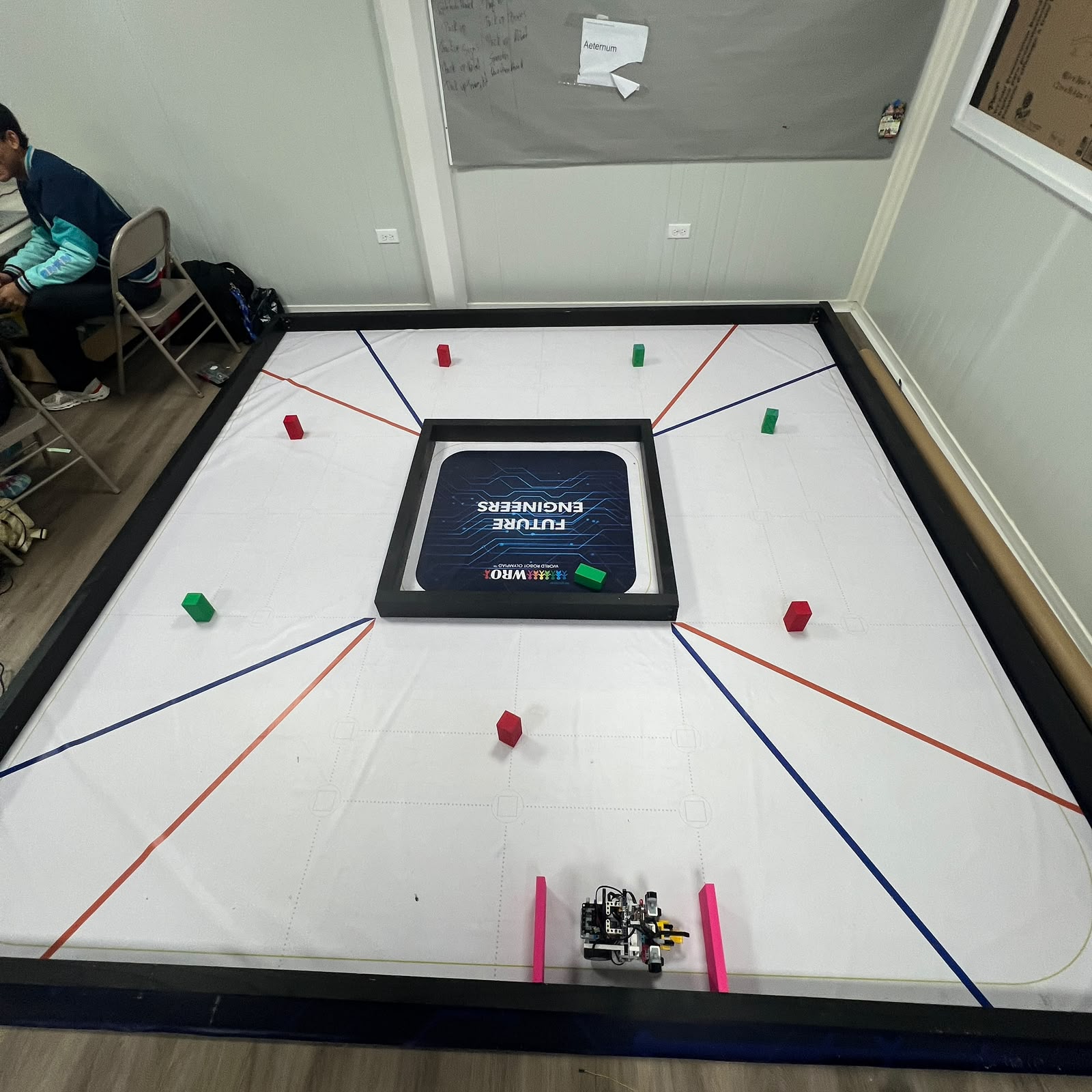 Figure 6.1. Piolín should be calibrated progressively: first as a stationary mechanical system, then through isolated dynamic tests, and finally on representative track conditions.
Calibration is the process of connecting Piolín's physical construction to the values used by its autonomous software.
A reconstructed robot should **not** be expected to reproduce the same trajectory simply because it uses the same source code. Small differences in steering center, sensor orientation, wheel behavior, camera mounting, drivetrain resistance, or lighting can change the physical meaning of a software constant.
The recommended calibration sequence is therefore:
```text
MECHANICAL INSPECTION
↓
STEERING CALIBRATION
↓
DRIVETRAIN CHECK
↓
ULTRASONIC CALIBRATION
↓
COLOR SENSOR CALIBRATION
↓
ROUND-SPECIFIC S1 CALIBRATION
↓
LOW-SPEED DYNAMIC TEST
↓
MANEUVER CALIBRATION
↓
FULL-TRACK VALIDATION
```
Piolín has two different round-specific S1 configurations:
```text
OPEN
S1 → EV3 Gyro Sensor
```
```text
OBSTACLES
S1 → Pixy2.1
```
The Gyro Sensor and Pixy2.1 are never installed simultaneously in the current competition architecture.
The permanent configuration is:
```text
A → propulsion
B → steering
S2 → LEFT Ultrasonic
S3 → RIGHT Ultrasonic
S4 → Color Sensor
```
---
## 6.1 Before Calibration
Calibration data is only meaningful when the robot begins in a known physical condition.
Before measuring anything, verify:
```text
Motor A secure
Motor B secure
rear drivetrain free
rear wheels secure
front steering linkage connected
steering pivots move freely
S2 physically on LEFT
S3 physically on RIGHT
S4 facing downward
Color Sensor casing secure
correct S1 device installed
```
If calibrating Obstacles, also verify:
```text
Pixy2.1 mount secure
Pixy2.1 3D-printed casing installed
camera orientation unchanged
S1 connection secure
```
If calibrating Open:
```text
Gyro mount secure
gyro orientation correct
```
Do not begin by changing software values if the robot has a mechanical fault.
The calibration principle is:
> **First make the physical system repeatable; then make the software match it.**
---
# 6.2 Record the Configuration
Before a calibration session, record the test configuration.
A simple log is enough:
| Field | Record |
| :--- | :--- |
| Date | — |
| Challenge | Open / Obstacles |
| Software file | — |
| Git commit / version | — |
| Battery condition | — |
| Mechanical changes since last calibration | — |
| S1 device | Gyro / Pixy2.1 |
| S2 | Left Ultrasonic |
| S3 | Right Ultrasonic |
| S4 | Color Sensor |
| Pixy casing installed | Yes / N/A |
| Color Sensor casing installed | Yes |
This prevents a calibration obtained from one physical version of Piolín from being confused with another.
---
# 6.3 Calibrate the Steering First
Sensor calibration is much less useful if Piolín cannot return to a repeatable steering center.
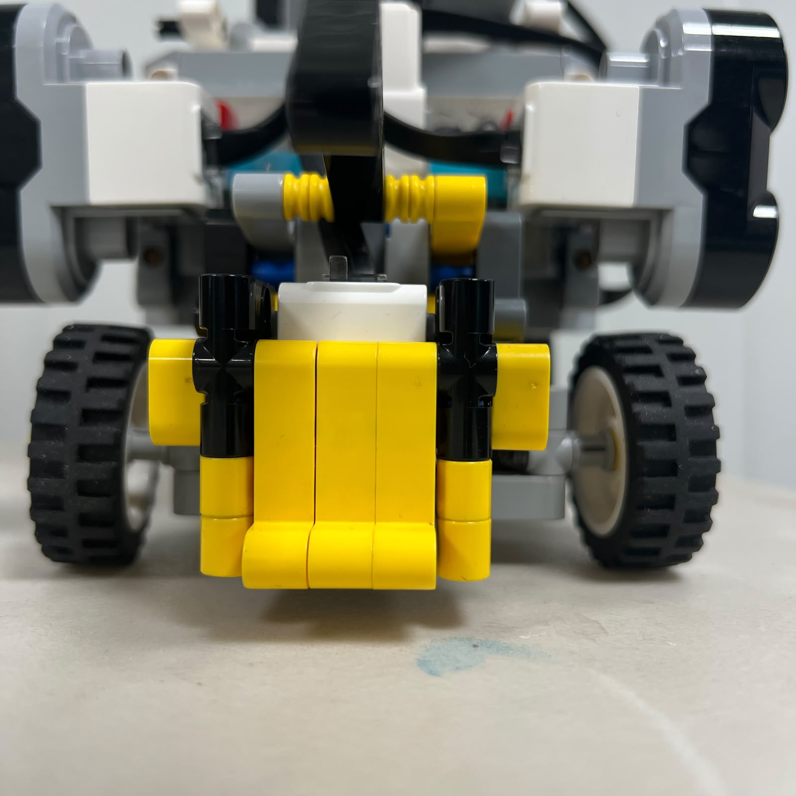 Figure 6.2. Establishing a repeatable mechanical center is the first important calibration step.
With Piolín stationary, place the front wheels as close as practical to the true straight-ahead position.
The desired relationship is:
```text
Motor B reference
↓
linkage centered
↓
front wheels approximately straight
```
Do not begin by adding a large software offset to compensate for visibly misaligned steering.
Instead:
```text
1. Inspect the linkage.
2. Center the front wheels mechanically.
3. Verify Motor B mount.
4. Establish the software center reference.
5. Test return-to-center repeatability.
```
A useful test is:
```text
CENTER
↓
LEFT
↓
CENTER
↓
RIGHT
↓
CENTER
```
Repeat this several times.
If the final center changes depending on whether the wheels approached from the left or right, mechanical backlash may be significant.
---
## 6.4 Determine the Useful Steering Range
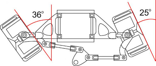 Figure 6.3. Steering calibration should relate Motor B commands to the actual front-wheel response.
Do not assume the maximum rotation available from Motor B is the maximum usable steering position.
Slowly move toward each side and identify the range where:
```text
linkage moves freely
no chassis interference occurs
Motor B is not forced against a hard stop
front wheels remain mechanically stable
```
Record:
| Position | Motor B Reference | Physical Observation |
| :--- | :---: | :--- |
| Center | — | Wheels approximately straight |
| Useful left limit | — | — |
| Useful right limit | — | — |
If possible, measure actual left and right wheel angles later.
Remember:
```text
Motor B angle
≠
physical wheel angle
```
because the linkage transforms the motor rotation.
---
# 6.5 Check the Drivetrain Before Distance Calibration
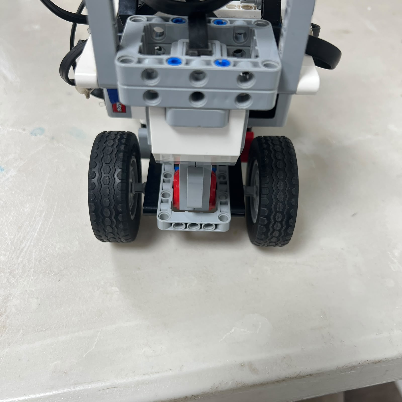 Figure 6.4. Encoder and speed calibration require a mechanically free and stable rear drivetrain.
Before using Motor A encoder values as a distance reference, inspect the drivetrain.
With the robot powered off, check:
```text
rear wheels rotate without unexpected binding
axles remain aligned
wheels do not rub the chassis
Motor A mount is secure
drivetrain geometry has not changed
```
Then perform a short low-speed forward test.
The vehicle should move without obvious:
```text
jerking
binding
severe drivetrain noise
one-sided resistance
```
Only after the mechanical system is stable should encoder-based distance be characterized.
---
## 6.6 Encoder-to-Distance Calibration
Choose a straight section and command a fixed Motor A encoder displacement.
For each trial:
```text
same start point
Motor B centered
same Motor A command
same encoder target
```
Measure the actual traveled distance.
Record:
| Trial | Motor A Rotation | Physical Distance | Notes |
| :---: | :---: | :---: | :--- |
| 1 | — | — | — |
| 2 | — | — | — |
| 3 | — | — | — |
| 4 | — | — | — |
| 5 | — | — | — |
A useful experimental conversion can later be calculated from:
```text
distance per motor degree
```
but it should be based on the actual V4 drivetrain rather than an assumed wheel diameter.
Repeat the procedure separately for reverse movement if reverse distance is used for recovery or parking.
---
# 6.7 Calibrate the Ultrasonic Sensors
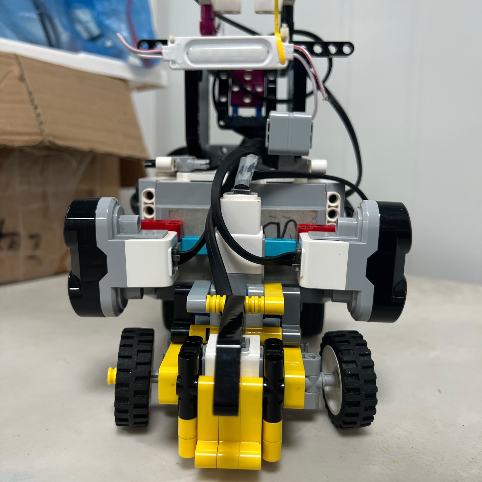 Figure 6.5. S2 and S3 should be physically aligned before any wall-distance values are calibrated.
The current permanent mapping is:
```text
S2 = LEFT
S3 = RIGHT
```
Never calibrate them only as:
```text
inner
outer
```
because those logical roles change according to course direction.
Place Piolín parallel to a flat wall at several measured positions and record the sensor output.
A useful table is:
| Physical Position | S2 Left Reading | S3 Right Reading | Vehicle Heading |
| :--- | :---: | :---: | :--- |
| Position 1 | — | — | Parallel |
| Position 2 | — | — | Parallel |
| Position 3 | — | — | Parallel |
Take several samples at each position.
The goal is to determine:
```text
normal reading range
sensor repeatability
useful wall distance
close-wall safety region
```
rather than finding one perfect number.
---
## 6.8 Test Ultrasonics with Vehicle Yaw
After the parallel tests, rotate Piolín slightly while keeping it in approximately the same lateral position.
Test:
```text
slightly nose toward wall
approximately parallel
slightly nose away from wall
```
Observe how the ultrasonic reading changes.
This experiment is important because:
```text
distance change
```
can result from:
```text
lateral position change
+
vehicle orientation change
```
The lateral sensors are therefore geometric references, not perfect global-position sensors.
During Open, the gyro helps separate orientation from lateral position.
---
# 6.9 Current Open Wall Target
The current Open code has used a working inner-wall target around:
```text
TARGET_INNER_MM = 270.0
```
or approximately:
```text
27 cm
```
This should be treated as a **current software starting point**, not as an immutable competition specification.
After reconstruction:
```text
start near the known working value
↓
observe straight behavior
↓
verify physical clearance
↓
adjust only if measured geometry requires it
```
Do not change the target merely because one isolated corner failed.
First determine whether the failure originated in:
```text
straight geometry
corner entry
gyro control
steering strength
mechanical alignment
```
---
# 6.10 Calibrate the Color Sensor
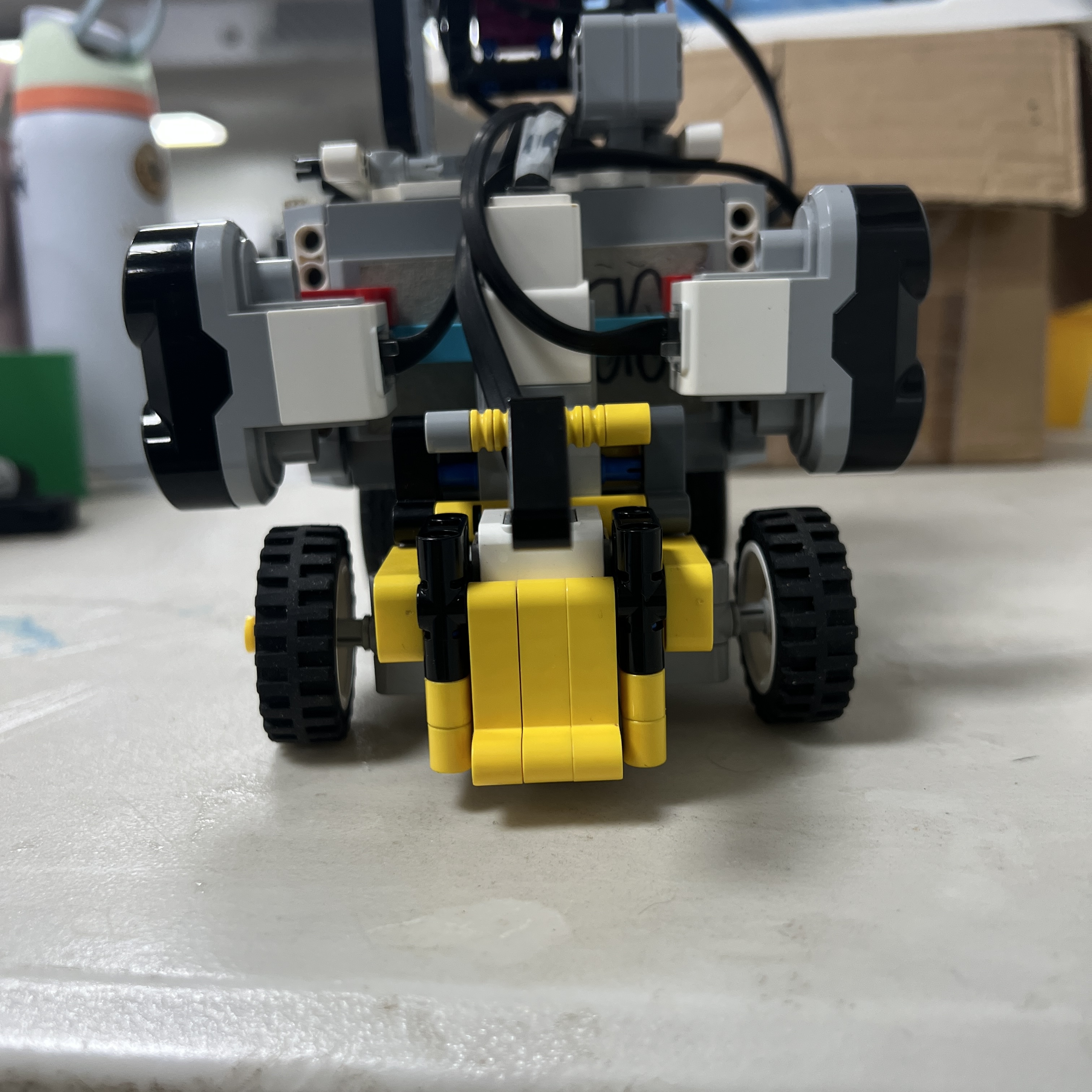 Figure 6.6. The Color Sensor must be calibrated with its current casing installed because the casing changes the optical environment.
The current floor categories are:
```text
BLUE
ORANGE
NORMAL FLOOR
```
Calibration must be performed with:
```text
S4 in its final position
current sensor height
current casing installed
real track surface
representative lighting
```
Do not calibrate the sensor detached from the robot and then assume those values will remain identical after installation.
---
## 6.11 Measure Blue, Orange, and Normal Floor
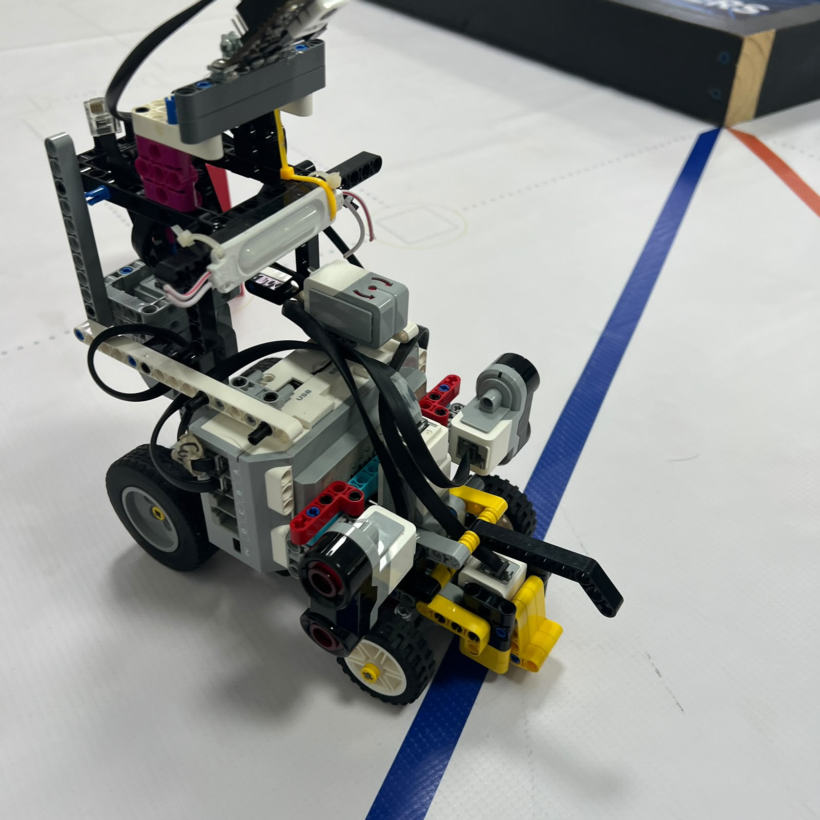 Figure 6.7. Blue calibration reference.
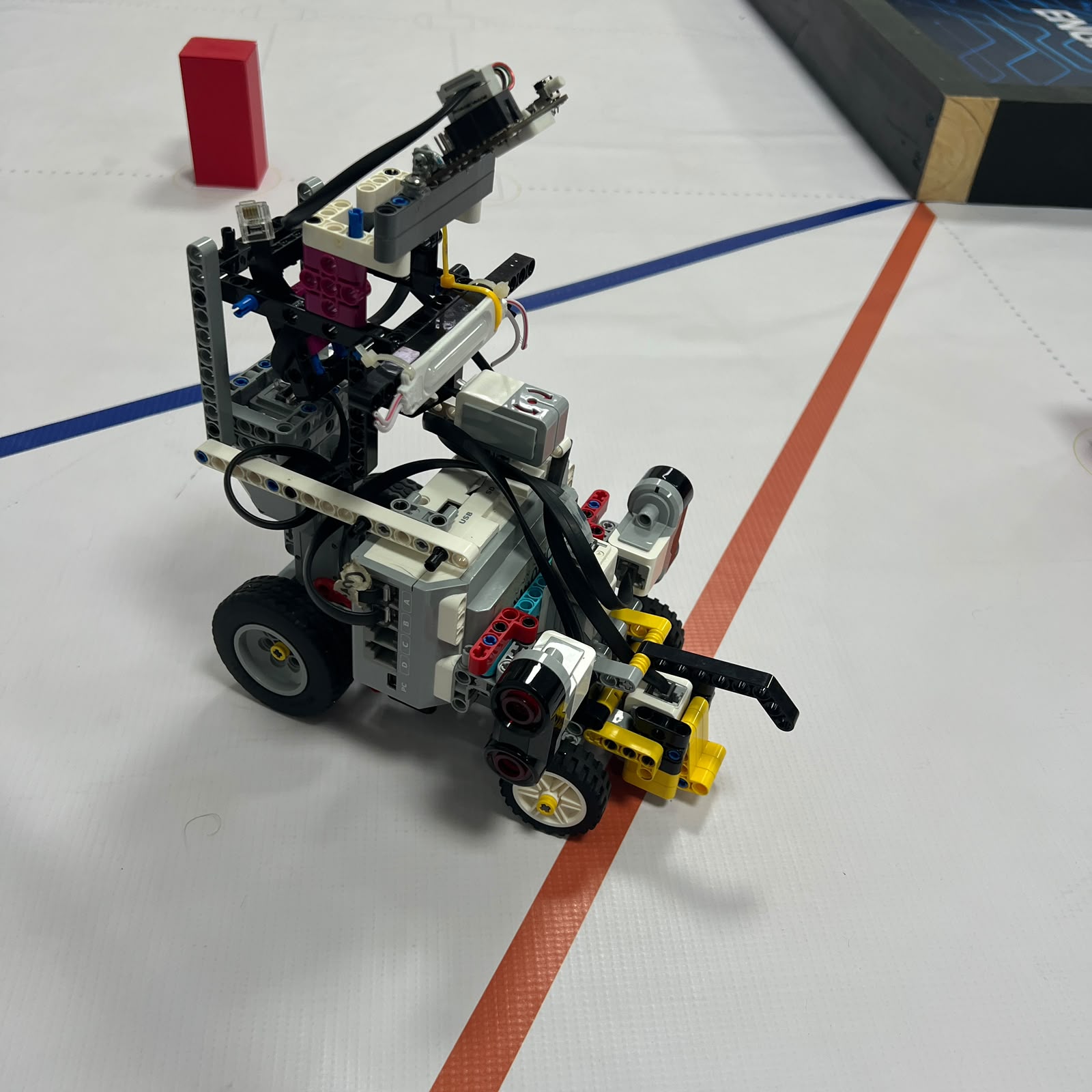 Figure 6.8. Orange calibration reference.
Collect repeated raw or RGB-style measurements from:
```text
Blue
Orange
normal floor
```
A calibration table can use:
| Surface | Sample 1 | Sample 2 | Sample 3 | Sample 4 | Sample 5 |
| :--- | :--- | :--- | :--- | :--- | :--- |
| Blue | — | — | — | — | — |
| Orange | — | — | — | — | — |
| Normal | — | — | — | — | — |
The objective is to identify **ranges** rather than single values.
A classifier should have enough separation that:
```text
Blue ≠ Orange
Blue ≠ Normal
Orange ≠ Normal
```
under representative conditions.
---
## 6.12 Verify Color Detection Dynamically
After stationary classification works, drive Piolín across each marking.
Test progressively:
```text
slow crossing
normal test speed
representative competition speed
```
A detection system must satisfy two different requirements:
```text
classify the color correctly
```
and:
```text
count one physical marking only once
```
The desired event sequence is:
```text
normal floor
↓
color detected
↓
color confirmed
↓
ONE event
↓
event locked
↓
leave colored region
↓
detector re-armed
```
If one line is counted twice, adjust event-lock or re-arm logic rather than widening color thresholds unnecessarily.
If the line is missed only at higher speed, investigate:
```text
confirmation delay
sampling
classification window
vehicle speed
```
before changing the physical color definition.
---
# 6.13 Calibrate the Open Gyro
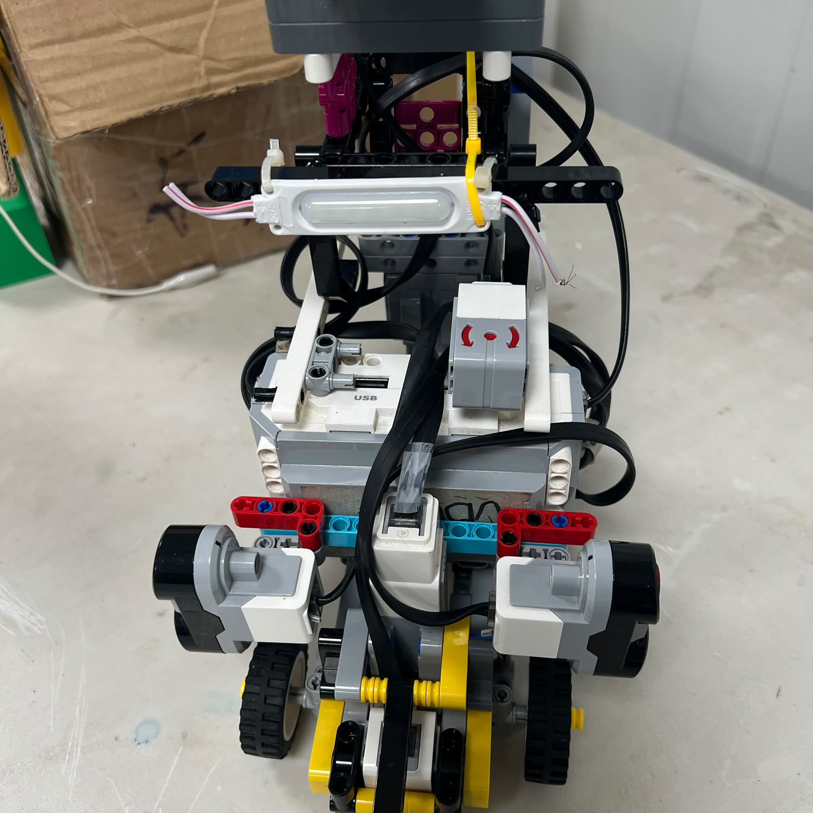 Figure 6.9. The Gyro Sensor must retain a fixed orientation relative to Piolín's chassis.
For Open, install:
```text
S1 → Gyro
```
and remove Pixy2.1.
Place Piolín stationary at the intended start orientation.
Then:
```text
1. Initialize the Gyro Sensor.
2. Keep the vehicle stationary.
3. Reset the angle reference to zero.
4. Confirm the reading remains near the expected reference.
5. Rotate Piolín manually and verify the sign of the angle.
6. Return to the initial heading and verify the reading behaves plausibly.
```
The current Open code concept uses a startup reset such as:
```python
gyro.reset_angle(0)
```
The exact implementation can vary with the current program, but the physical requirement is always a known initial heading.
---
## 6.14 Check Gyro Sign Before Driving
This test is essential.
Rotate Piolín manually:
```text
clockwise
```
and then:
```text
counterclockwise
```
Observe whether the software reports the direction expected by the controller.
If the sign is opposite from the assumptions used in corner logic:
```text
do not compensate randomly in multiple steering constants
```
First correct the interpretation of the gyro direction.
A sign error can make an otherwise correct corner controller appear completely inverted.
---
## 6.15 Gyro Straight-Line Calibration
The gyro supports heading stabilization during Open.
A heading error can be written conceptually as:
```text
heading_error =
desired_heading - measured_heading
```
The current Open controller has used PD-style gyro correction with working development values including:
```text
GYRO_KP = 0.45
GYRO_KD = 0.30
GYRO_MAX_CORRECTION = 6.5
```
These are **current working calibration values**, not guaranteed final constants.
After rebuilding Piolín:
```text
use the known-good values as a starting point
↓
test at low speed
↓
observe heading stability
↓
change one gain at a time only if needed
```
Typical symptoms are:
| Behavior | Possible Adjustment Area |
| :--- | :--- |
| Slow heading correction | Proportional response may be weak |
| Repeated left/right oscillation | Correction may be too aggressive or delayed |
| Sharp reaction to short disturbances | Derivative response or correction limit |
| Stable heading but wrong wall position | Ultrasonic geometry, not gyro gain |
The gyro should stabilize orientation without replacing lateral wall control.
---
# 6.16 Calibrate Open Corners Separately
Do not tune twelve corners at once.
First create a controlled single-corner test.
Use approximately the same:
```text
starting position
vehicle heading
Motor A speed
course direction
```
for repeated trials.
A useful corner sequence is:
```text
stable straight
↓
corner evidence
↓
steering begins
↓
gyro angle changes
↓
vehicle rotates
↓
steering releases
↓
S2/S3 geometry becomes usable
```
Measure or record:
```text
gyro angle when turn begins
gyro behavior during turn
gyro angle near release
S2/S3 at exit
physical exit position
```
Do not assume the ideal theoretical corner must release at exactly 90°.
The final value should be based on the actual Ackermann vehicle and its useful corner exit.
---
# 6.17 Validate Both Open Directions
The course can operate in two directions.
The first valid color establishes:
```text
BLUE first
→ counterclockwise
```
```text
ORANGE first
→ clockwise
```
Calibration must therefore test both cases.
For counterclockwise:
```text
S2 LEFT = inner
S3 RIGHT = outer
```
For clockwise:
```text
S3 RIGHT = inner
S2 LEFT = outer
```
The physical sensors do not move or swap ports.
If one direction works and the other fails, compare:
```text
inner/outer software mapping
left/right steering behavior
corner thresholds
mechanical steering asymmetry
```
rather than rewiring S2 and S3.
---
# 6.18 Calibrate Pixy2.1 for Obstacles
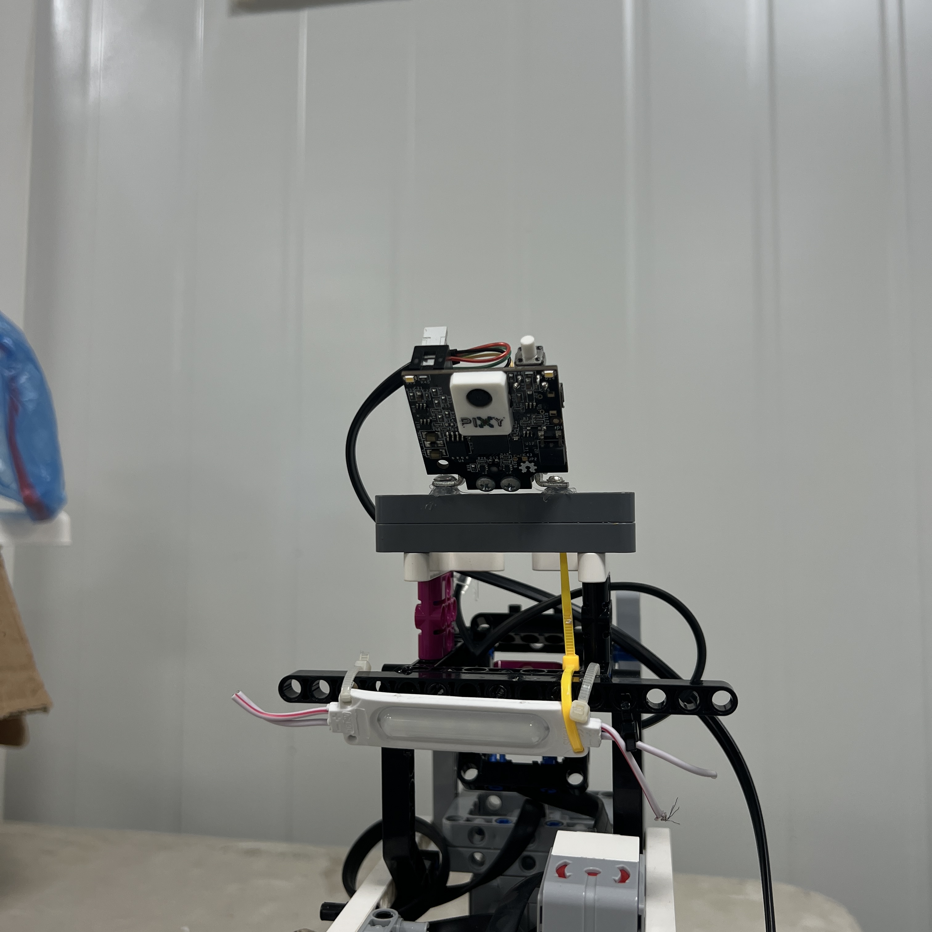 Figure 6.10. Pixy2.1 must be calibrated in its complete current installation, including its 3D-printed casing.
For the Obstacle Challenge:
```text
S1 → Pixy2.1
```
and the Gyro Sensor is removed.
The current Pixy2.1 assembly includes a **3D-printed casing**.
The casing is part of the active camera installation and must remain installed during final calibration because changing the casing can alter:
```text
camera mounting
camera orientation
lighting around the camera
effective field of view
```
Calibration performed without the casing should not automatically be treated as final calibration for the competition assembly.
---
## 6.19 Verify Pixy Signature Mapping
The current signatures are:
```text
sig1 → PINK → parking
sig2 → RED → pass RIGHT
sig3 → GREEN → pass LEFT
```
Before dynamic obstacle testing, verify each color individually.
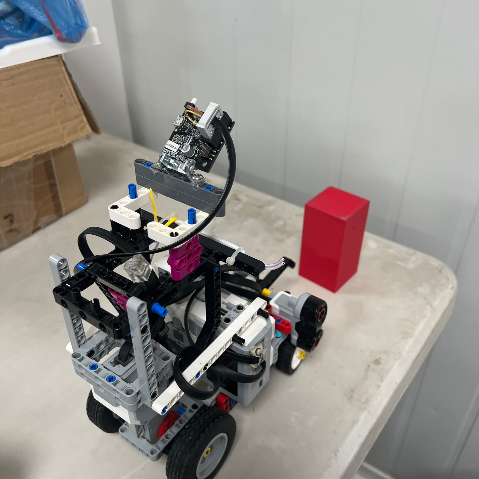 Figure 6.11. Red should consistently map to signature 2 and the pass-right rule.
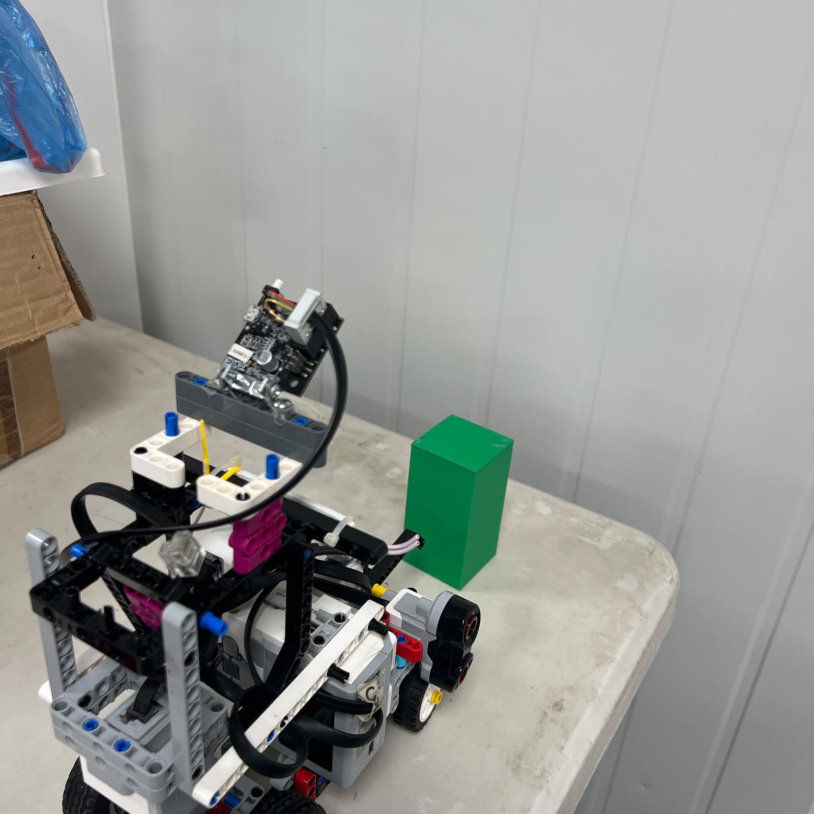 Figure 6.12. Green should consistently map to signature 3 and the pass-left rule.
Check:
```text
Red → sig2
Green → sig3
Pink → sig1
```
and also confirm that:
```text
Red does not become Green
Green does not become Red
small background regions do not dominate target selection
```
The EV3 software must use exactly the same signature mapping as Pixy.
---
# 6.20 Calibrate Pixy Image Geometry
Pixy block information can include:
```text
x
y
width
height
```
Start with one pillar and move it across the camera view.
Record:
| Position | Signature | x | y | Width | Height |
| :--- | :---: | :---: | :---: | :---: | :---: |
| Left region | — | — | — | — | — |
| Near center | — | — | — | — | — |
| Right region | — | — | — | — | — |
This verifies the camera coordinate direction.
Then move the same pillar through several useful approach distances and observe:
```text
width
height
```
The expected qualitative tendency is:
```text
closer target
→ larger apparent block
```
but block size should not be presented as exact physical distance unless that relationship is separately calibrated.
---
# 6.21 Never Calibrate Passing Side from Image Side
One of the most important obstacle rules is:
```text
RED
→ pass RIGHT
GREEN
→ pass LEFT
```
This remains true regardless of where the pillar appears in the image.
Therefore:
```text
signature
→ passing rule
```
while:
```text
x
→ current visual geometry
```
A Red pillar appearing on the left side of the image is **still a Red pass-right obstacle**.
Do not calibrate logic that says:
```text
target left of image
→ always steer left
```
because this can invert the competition rule depending on camera perspective.
---
# 6.22 Calibrate Target Relevance
Very distant pillars should not continuously dominate steering.
Start with one pillar far away and gradually move Piolín closer.
Observe:
```text
when signature becomes stable
how x changes
how width/height change
when the pillar becomes physically relevant
```
The intended behavior is:
```text
weak / distant detection
→ little or no major steering authority
```
and:
```text
relevant target
→ avoidance state becomes active
```
Do not set the final relevance threshold from one isolated observation.
Test:
```text
Red
Green
different lateral positions
representative lighting
```
before accepting the parameter.
---
# 6.23 Calibrate Multiple-Target Selection
Once single-object detection works, place more than one valid pillar in view.
Test conditions such as:
```text
Red + Green
near Red + distant Green
near Green + distant Red
central target + peripheral target
```
The software should select the **most relevant current obstacle**, not simply the first block returned by Pixy.
The exact scoring method can use a combination of:
```text
valid signature
apparent size
x/y position
current state
previous target
```
but final weighting should come from repeated track testing.
---
# 6.24 Calibrate Target Lock and Pass Confirmation
After Piolín commits to a pillar, the target should remain stable long enough to complete the maneuver.
Conceptually:
```text
target selected
↓
temporary lock
↓
avoidance
↓
vehicle passes pillar
↓
physical clearance confirmed
↓
target released
```
Do not release the target merely because Pixy loses it for one update.
Steering changes the camera viewpoint, so:
```text
target disappeared from image
```
does not necessarily mean:
```text
pillar physically passed
```
Use lateral ultrasonic behavior and vehicle state as additional evidence.
The intended pass logic is approximately:
```text
Pixy detects pillar
↓
avoid
↓
lateral geometry changes
↓
vehicle moves beyond pillar
↓
space opens again
↓
release target
```
The exact numerical threshold remains a calibration value.
---
# 6.25 Calibrate Obstacle Recovery
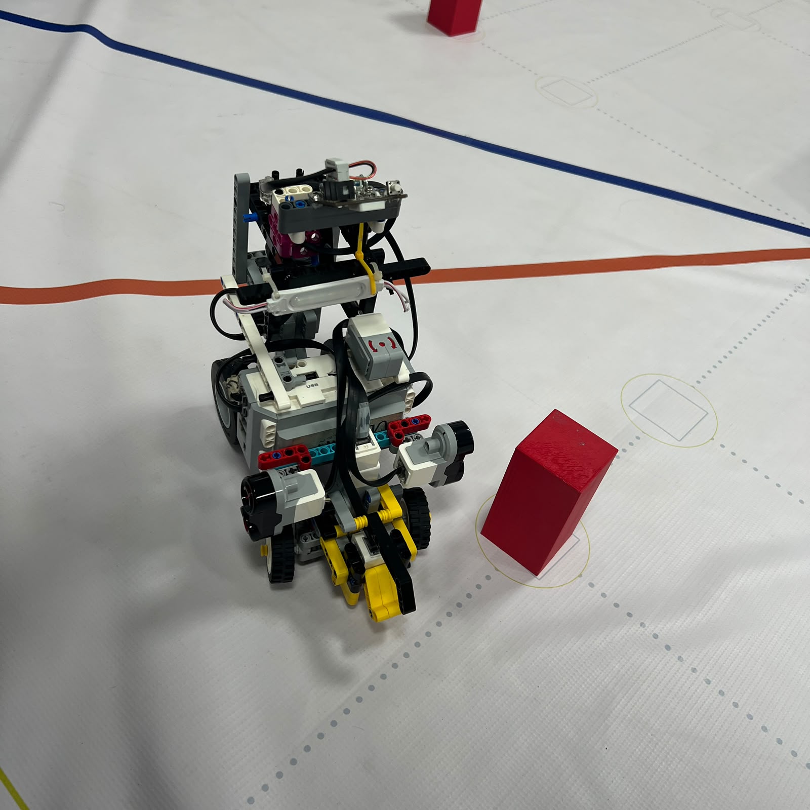 Figure 6.13. A successful obstacle calibration includes both the required pass and a controlled recovery afterward.
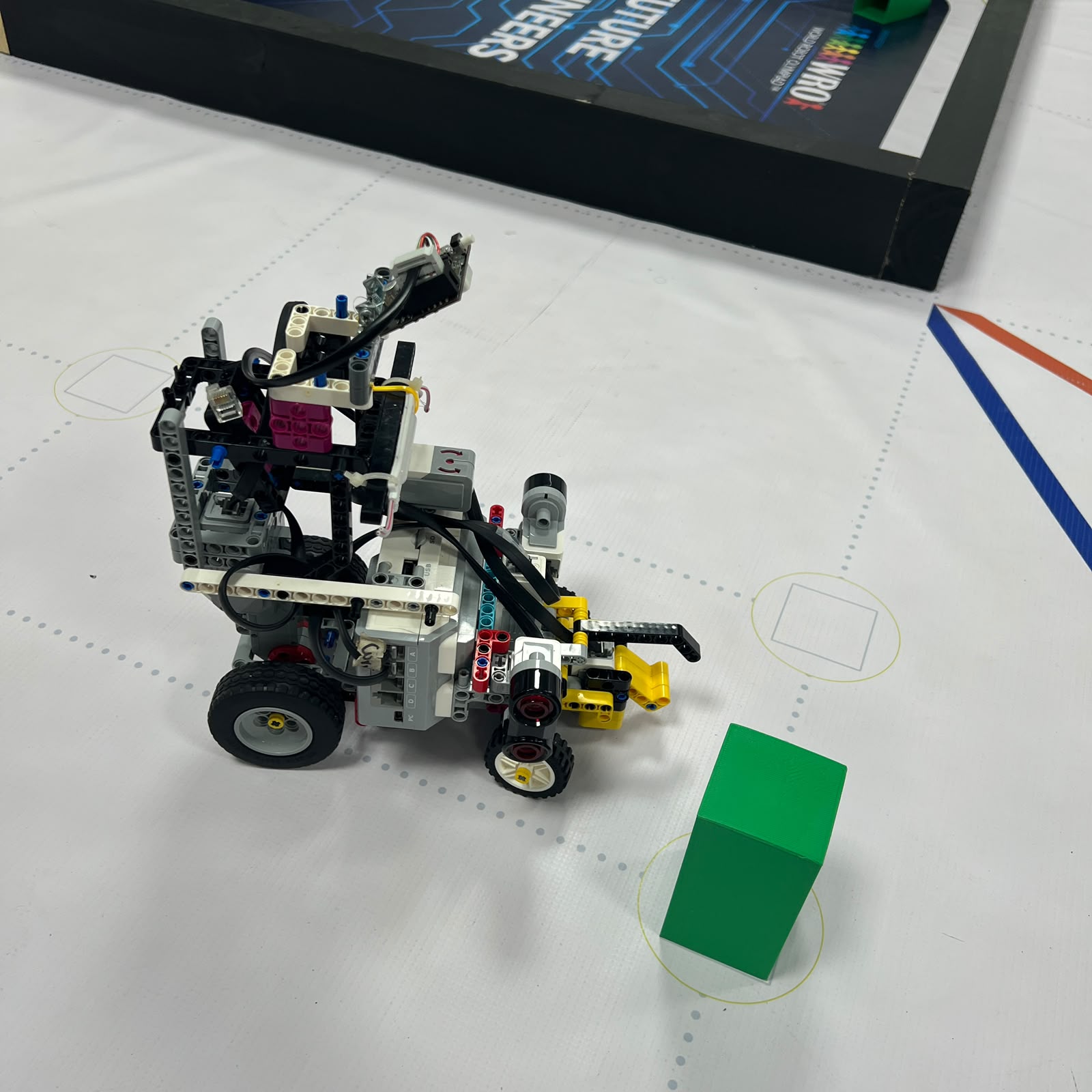 Figure 6.14. Red and Green maneuvers should be validated independently because the real steering system may not behave perfectly symmetrically.
A pillar test is incomplete if Piolín only avoids the obstacle.
The full trajectory is:
```text
DETECT
↓
AVOID
↓
PASS
↓
COUNTERSTEER
↓
RECOVER
```
After passing the pillar, observe:
```text
S2
S3
vehicle heading
residual steering
wall clearance
```
The recovery should begin late enough that Piolín does not steer back into the pillar, but early enough that it does not continue toward the outside wall.
Test Red and Green separately.
Do not assume the same absolute steering constants will necessarily create identical physical trajectories in both directions.
---
# 6.26 Calibrate Parking Last
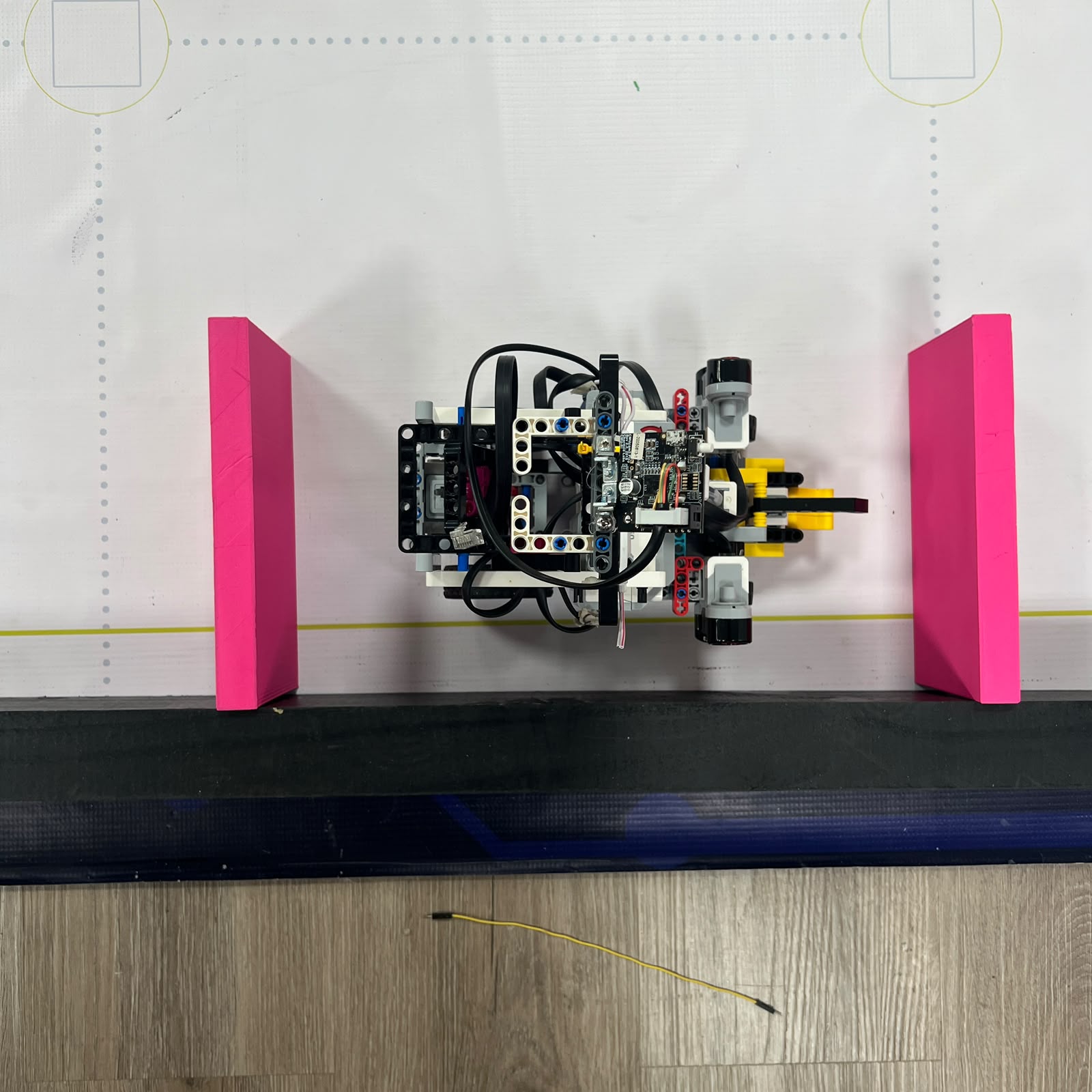 Figure 6.15. Parking should be calibrated only after course progression, steering, and displacement behavior are sufficiently repeatable.
Parking depends on several already-calibrated subsystems:
```text
course progression
steering center
Motor A displacement
wall geometry
final approach state
```
During Obstacles, the current vision system also reserves:
```text
sig1 → Pink → parking reference
```
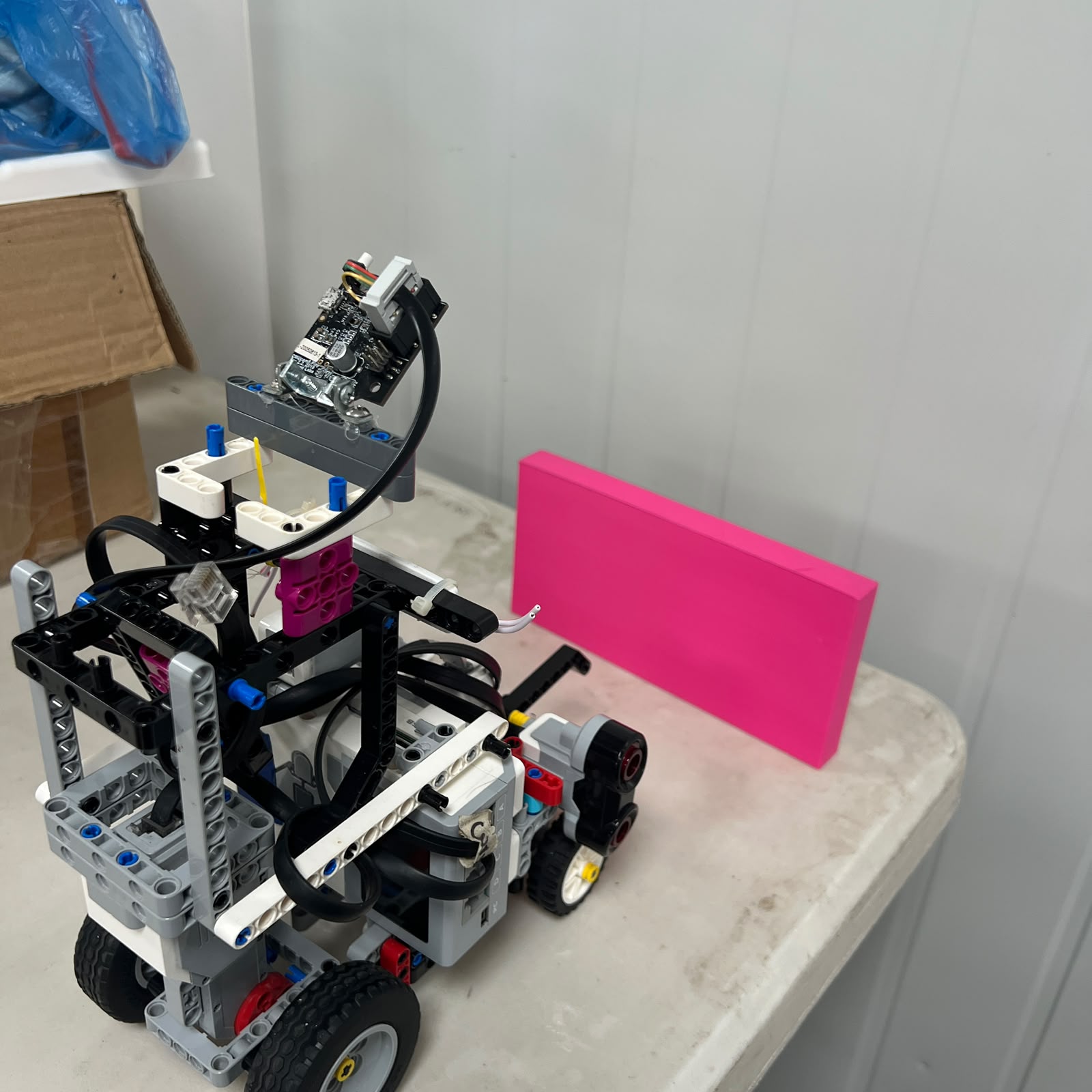 Figure 6.16. Pink visual detection can support parking, but should be combined with the correct course state.
Do not calibrate parking as:
```text
Pink visible
→ stop immediately
```
or:
```text
12th event
→ arbitrary timed stop
```
unless repeated testing shows that such a condition is sufficient.
A stronger final strategy can combine:
```text
expected progress reached
+
parking state enabled
+
physical parking reference
+
controlled drivetrain displacement
+
lateral geometry
```
The current parking implementation remains under development.
---
# 6.27 Move from Static to Dynamic Calibration
Each subsystem should progress through the same general test hierarchy:
```text
STATIC
↓
LOW SPEED
↓
REPRESENTATIVE SPEED
↓
ISOLATED MANEUVER
↓
REPEATED MANEUVER
↓
FULL RUN
```
For example, Pixy calibration should progress from:
```text
stationary Red detection
```
to:
```text
slow Red approach
```
to:
```text
full Red avoidance + recovery
```
Similarly, the Color Sensor should progress from:
```text
stationary Blue measurement
```
to:
```text
Blue crossing at actual driving speed
```
Static calibration proves that a sensor can recognize a condition.
Dynamic calibration proves that the complete robot can use that information in time.
---
# 6.28 Change One Variable at a Time
Suppose an Open corner is too wide.
Possible causes include:
```text
turn begins too late
Motor A speed too high
steering angle too weak
gyro release threshold wrong
starting geometry wrong
```
Changing all of them at once destroys the value of the test.
Instead:
```text
OBSERVE
↓
IDENTIFY LIKELY CAUSE
↓
CHANGE ONE VARIABLE
↓
REPEAT SAME TEST
↓
COMPARE
```
The same principle applies to Obstacles.
If Green detection is unreliable, do not simultaneously:
```text
retrain Pixy
change camera angle
change Motor A speed
change steering polarity
change wall control
```
Choose the variable that matches the observed failure and test it independently.
---
# 6.29 Calibration Checklist — Open
Before attempting a complete Open run, verify:
| Calibration | Required Result |
| :--- | :--- |
| Steering center | Repeatable |
| Steering limits | No binding |
| Motor A | Correct direction and stable movement |
| S2 | Left geometry plausible |
| S3 | Right geometry plausible |
| S4 Blue | Recognized |
| S4 Orange | Recognized |
| Color event lock | One physical mark = one event |
| Gyro zero | Stable startup reference |
| Gyro sign | Correct |
| Straight control | No severe oscillation |
| CCW mapping | S2 inner / S3 outer |
| CW mapping | S3 inner / S2 outer |
| Single corner | Repeatable |
| Corner exit | Useful wall geometry |
| Multi-corner test | Stable enough for full run |
A full three-lap test should come **after** these items work individually.
---
# 6.30 Calibration Checklist — Obstacles
Before attempting a complete Obstacle run, verify:
| Calibration | Required Result |
| :--- | :--- |
| Steering center | Repeatable |
| Motor A | Stable |
| S2 | Left geometry valid |
| S3 | Right geometry valid |
| S4 | Course-state detection valid |
| Pixy casing | Installed and secure |
| Pixy communication | Stable |
| `sig1` | Pink |
| `sig2` | Red |
| `sig3` | Green |
| Red rule | Pass RIGHT |
| Green rule | Pass LEFT |
| Pixy x direction | Verified |
| Apparent-size behavior | Plausible |
| Multiple targets | Relevant target selected |
| Target lock | Stable during maneuver |
| Target release | Occurs after pass |
| Red maneuver | Pass + recovery |
| Green maneuver | Pass + recovery |
| Consecutive pillars | State resets correctly |
---
# 6.31 Save Known-Good Calibration
Once a configuration performs well repeatedly, preserve it.
Record:
```text
software file
Git commit
mechanical configuration
sensor configuration
calibration constants
test conditions
```
Do not rely only on memory or filenames such as:
```text
final.py
final2.py
workingnew.py
```
A known-good state should be reproducible through version control.
A calibration change should ideally answer:
```text
what changed?
why was it changed?
what test improved?
what test became worse?
```
This turns software tuning into engineering evidence.
---
# 6.32 When to Recalibrate
Recalibration or verification should occur after significant physical changes.
Examples include:
```text
Motor B remounted
steering linkage changed
rear drivetrain changed
ultrasonic sensor moved
Color Sensor moved
Color Sensor casing changed
Gyro moved
Pixy2.1 moved
Pixy casing changed
camera angle changed
major chassis modification
```
Not every change requires rebuilding every calibration table.
However, the previous values should not automatically be trusted without verification.
A useful rule is:
> **If the physical relationship between a sensor, actuator, and the chassis changes, recheck the calibration that depends on that relationship.**
---
# 6.33 What Should Be Measured Before Final Publication
Several values are still development parameters rather than finalized engineering specifications.
Before publishing final quantitative calibration data, measure and verify:
```text
steering-center reference
useful left steering limit
useful right steering limit
physical wheel angles
encoder-to-distance conversion
S2 repeatability
S3 repeatability
final inner-wall target
wall safety thresholds
Blue classification range
Orange classification range
Color Sensor event timing
gyro drift
gyro corner behavior
Pixy camera geometry
Pixy target relevance thresholds
target-lock behavior
pillar-pass condition
Red maneuver repeatability
Green maneuver repeatability
parking repeatability
```
Do not replace missing measurements with estimated values simply to make the documentation look complete.
A documented method with an empty measurement field is stronger engineering evidence than a fabricated specification.
---
# 6.34 Complete Calibration Workflow
The complete reproducible process can be summarized as:
```text
RECONSTRUCT PIOLÍN
│
▼
VERIFY MECHANICS
│
▼
CENTER STEERING
│
▼
CHECK DRIVETRAIN
│
▼
CALIBRATE S2/S3
│
▼
CALIBRATE S4
│
┌─────────┴─────────┐
│ │
▼ ▼
OPEN OBSTACLES
│ │
▼ ▼
GYRO S1 PIXY2.1 S1
│ │
▼ ▼
heading / corners signatures / geometry
│ │
└─────────┬─────────┘
▼
LOW-SPEED TEST
│
▼
MANEUVER TEST
│
▼
REPEATED TEST
│
▼
FULL TRACK
│
▼
RECORD RESULT
│
▼
SAVE KNOWN-GOOD
```
---
# 6.35 Final Engineering Assessment
Calibrating Piolín means establishing a repeatable relationship between the **physical robot** and the **software values that control it**.
The process begins mechanically:
```text
steering center
drivetrain
sensor mounts
```
then moves to sensing:
```text
S2/S3 geometry
S4 floor classification
```
and finally reaches the round-specific perception system:
```text
OPEN
→ Gyro
```
```text
OBSTACLES
→ Pixy2.1
```
The current Color Sensor must be calibrated with its light-isolation casing installed, and the current Pixy2.1 must be calibrated with its **3D-printed casing installed**, because both enclosures are part of the physical conditions under which the sensors operate.
Open calibration must preserve the distinction between:
```text
ultrasonic lateral geometry
```
and:
```text
gyro orientation
```
while Obstacle calibration must preserve the distinction between:
```text
Pixy signature
→ required passing side
```
and:
```text
Pixy image coordinates
→ visual geometry
```
The final rule remains:
```text
RED
→ pass RIGHT
GREEN
→ pass LEFT
```
regardless of the target's image position.
Calibration should always progress from isolated, measurable behavior toward complete autonomous runs. A full-track success should be the **result** of correctly calibrated subsystems, not the only method used to search for working constants.
The central reproducibility principle is:
> **Do not copy numbers and hope the reconstructed robot behaves identically. Rebuild the same physical relationships, measure the resulting system, use known-good values as starting points, and verify them through controlled tests.**
This approach allows Piolín's software values to remain connected to the real V4 vehicle and makes future mechanical or software changes easier to understand, reproduce, and validate.
---
### [← Back to PiolínTech Main README](../../README.md)