# 1. Engineering Process
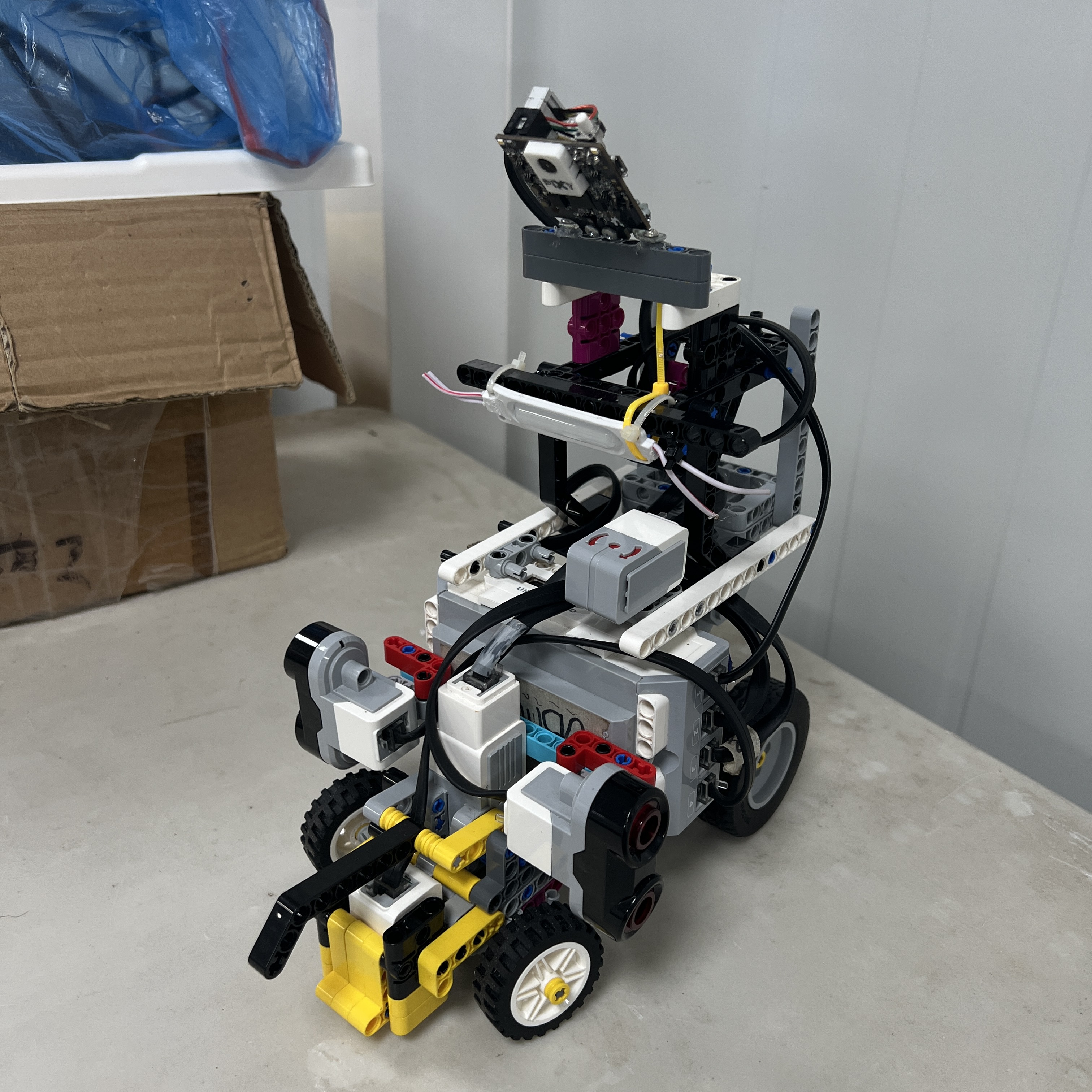 Figure 1.1. Piolín is the result of an iterative engineering process in which mechanical design, sensing, software, and competition strategy were developed together.
PiolínTech developed Piolín through an **iterative systems-engineering process** rather than by designing the complete robot once and then only programming it.
Throughout development, changes in one subsystem repeatedly affected others.
For example:
```text
camera position
→ changes visual detections
→ changes obstacle timing
→ changes steering requirements
→ changes wall clearance
```
and:
```text
steering geometry
→ changes turning radius
→ changes corner timing
→ changes sensor orientation
→ changes software thresholds
```
For this reason, the team treats Piolín as one interacting system composed of:
```text
MECHANICAL DESIGN
PROPULSION
STEERING
SENSORS
PERCEPTION
NAVIGATION SOFTWARE
STATE MANAGEMENT
COURSE STRATEGY
TESTING
```
The engineering process follows a repeated cycle:
```text
OBSERVE
↓
IDENTIFY THE FIRST FAILURE
↓
FORM A HYPOTHESIS
↓
CHANGE ONE RELEVANT PART
↓
TEST
↓
MEASURE / RECORD
↓
KEEP OR REJECT
↓
ITERATE
```
This process has produced several major changes to Piolín's hardware and software architecture during development.
---
## 1.1 From Competition Requirements to Engineering Requirements
The first step is translating WRO Future Engineers requirements into engineering problems.
Piolín must be able to:
```text
propel itself
steer predictably
detect course boundaries
recognize floor landmarks
determine course direction
handle corners
identify Red and Green pillars
pass each pillar on the required side
recover after avoidance
track course progression
reach the parking area
stop autonomously
```
Those competition tasks become subsystem requirements.
| Competition Need | Engineering Requirement |
| :--- | :--- |
| Navigate straights | Stable propulsion + lateral sensing |
| Turn corners | Predictable Ackermann steering + corner logic |
| Red pillar | Vision classification + pass-right strategy |
| Green pillar | Vision classification + pass-left strategy |
| Avoid walls | Lateral ultrasonic safety |
| Determine direction | Floor-marking detection |
| Track course progress | Event confirmation and counting |
| Park | Final-state sensing, geometry, and controlled stopping |
This decomposition allows each difficult behavior to be tested independently before integration.
---
# 1.2 Mechanical and Software Development Were Coupled
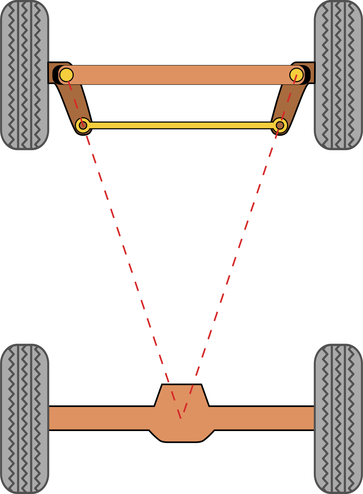 Figure 1.2. The steering mechanism and software controller were developed as one system because software steering values only become meaningful through the physical Ackermann geometry.
Piolín uses:
```text
Motor A
→ rear propulsion
```
and:
```text
Motor B
→ front Ackermann-style steering
```
This architecture was selected because it creates vehicle behavior similar to a small car.
However, it also means that software cannot command:
```text
rotate in place
```
or:
```text
move directly sideways
```
Every turn depends on:
```text
front-wheel angle
+
forward/reverse movement
+
vehicle geometry
```
As a result, PiolínTech could not tune software independently from the physical steering mechanism.
When the steering geometry changed, software values such as:
```text
turn strength
turn duration
recovery strength
parking trajectory
```
had to be evaluated again.
Likewise, when software revealed inconsistent steering behavior, the team inspected:
```text
linkage rigidity
wheel angles
Motor B mounting
mechanical play
wheel support
```
instead of assuming every failure was caused by code.
This relationship between software and mechanics became one of the main engineering lessons of the project.
---
# 1.3 Sensor Architecture Evolved Through Testing
The sensing system also changed significantly during development.
Earlier prototypes explored additional or different sensors, including camera systems that required extra intermediate electronics.
Those experiments were valuable because they revealed practical limitations such as:
```text
integration complexity
available EV3 ports
lighting sensitivity
field-of-view limitations
communication reliability
software complexity
```
The current architecture was simplified into two round-specific configurations.
### Open Challenge
```text
S1 → EV3 Gyro Sensor
S2 → LEFT Ultrasonic Sensor
S3 → RIGHT Ultrasonic Sensor
S4 → EV3 Color Sensor
```
### Obstacle Challenge
```text
S1 → Pixy2.1
S2 → LEFT Ultrasonic Sensor
S3 → RIGHT Ultrasonic Sensor
S4 → EV3 Color Sensor
```
This architecture deliberately accepts one important constraint:
> **The Gyro Sensor and Pixy2.1 are not installed simultaneously.**
Instead of forcing every sensor onto the robot at the same time, PiolínTech uses the sensor that contributes the most useful information for each round.
---
# 1.4 Why the Round-Specific Architecture Was Chosen
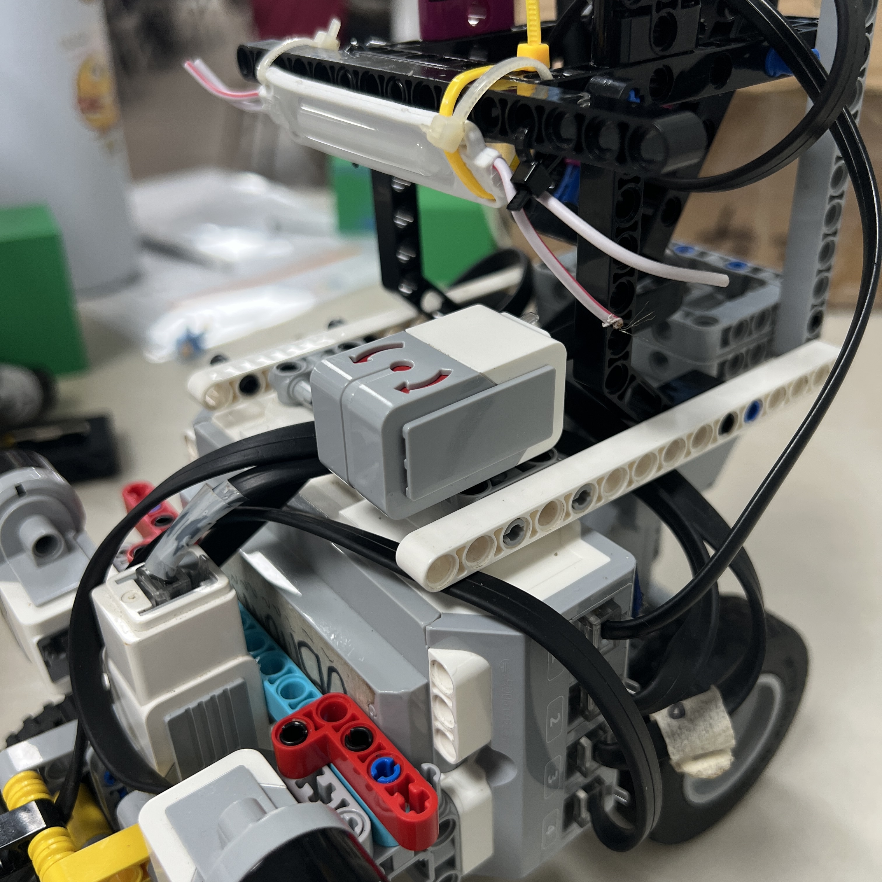 Figure 1.3. Open Challenge configuration: S1 is dedicated to heading stabilization through the EV3 Gyro Sensor.
For Open, the primary navigation problem is:
```text
drive stable straights
manage corners
reduce heading drift
track course progress
```
The Gyro Sensor provides direct heading information, making it valuable for this problem.
During Obstacles, the main additional problem becomes:
```text
Which pillar is ahead?
Is it Red or Green?
Where is it in the forward field of view?
```
For this reason, S1 changes to Pixy2.1.
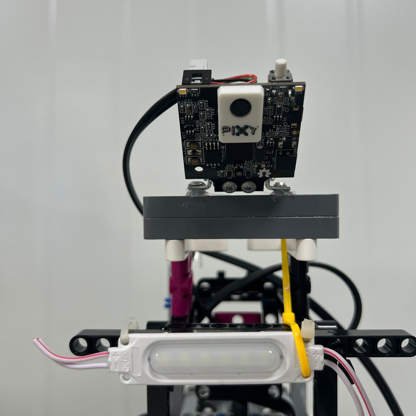 Figure 1.4. Obstacle Challenge configuration: Pixy2.1 occupies S1 and becomes Piolín's forward perception sensor.
The decision can be summarized as:
```text
OPEN
heading information has greater value
→ Gyro on S1
```
```text
OBSTACLES
forward object identity has greater value
→ Pixy2.1 on S1
```
This reduced unnecessary hardware complexity while preserving:
```text
two lateral ultrasonics
floor color sensing
same propulsion system
same steering system
```
between both configurations.
---
# 1.5 From HuskyLens Prototyping to Pixy2.1
An important example of iterative engineering was the evolution of the obstacle-vision subsystem.
Earlier development investigated a:
```text
HuskyLens
+
Arduino Nano
+
EV3
```
architecture.
This approach provided valuable experience with:
```text
color detection
external-camera integration
object identification
communication between controllers
```
but also introduced additional complexity.
The final current Obstacle architecture instead uses:
```text
Pixy2.1
→ EV3 S1
```
directly.
The change reduced the number of active components involved in the perception chain.
The historical system remains useful engineering evidence, but it is documented as **legacy development**, not as the current robot architecture.
This distinction is important because engineering documentation should show:
```text
what was tested
```
without confusing it with:
```text
what is currently used
```
The project therefore preserves earlier experiments while clearly separating them from the final active architecture.
---
# 1.6 Development of the Ultrasonic Strategy
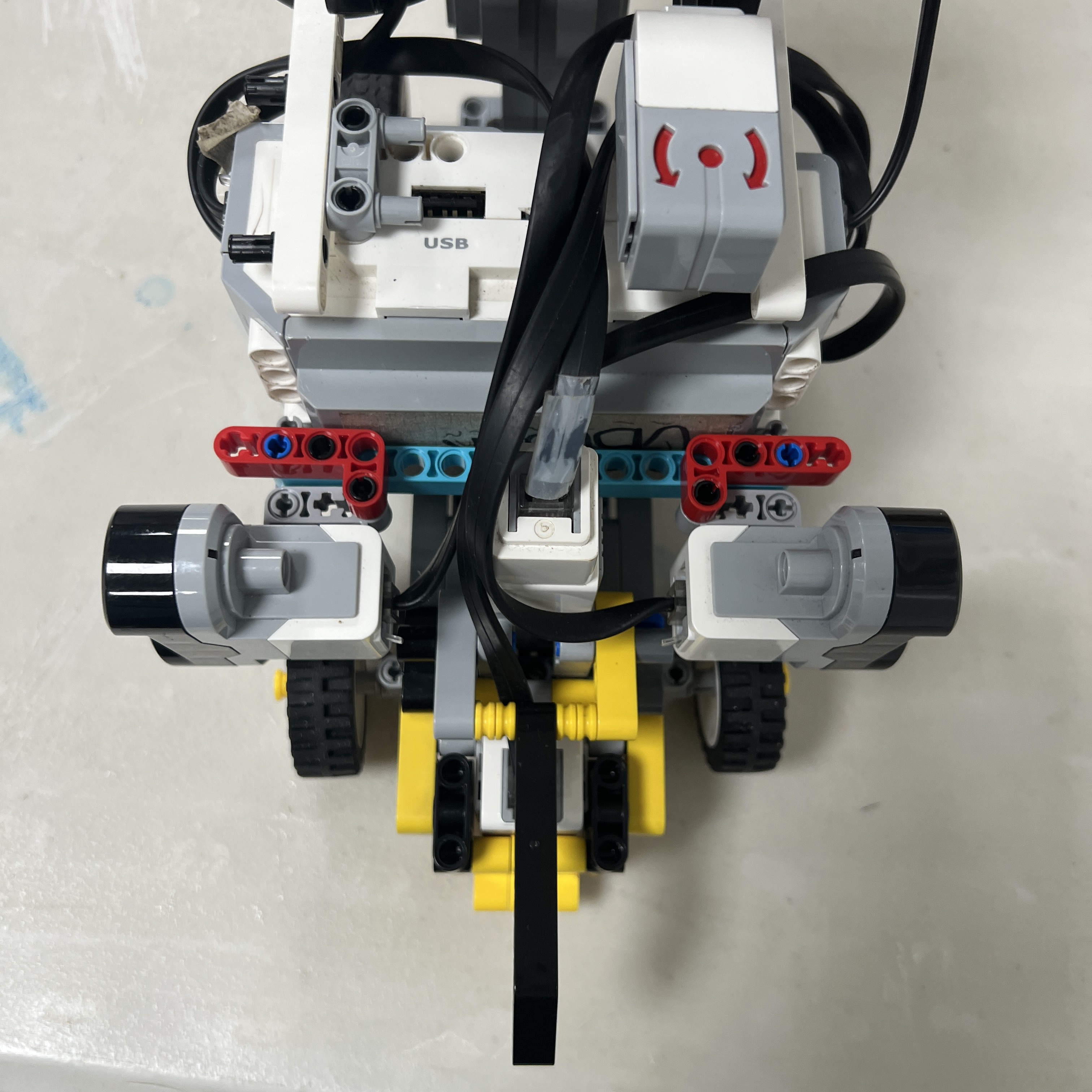 Figure 1.5. The current ultrasonic system uses two permanent lateral sensors rather than relying on a permanent front ultrasonic sensor.
Piolín's ultrasonic strategy also evolved.
The current physical convention is fixed:
```text
S2 = LEFT
S3 = RIGHT
```
The two sensors are mounted laterally and are used to understand:
```text
wall clearance
track-relative geometry
physical safety
post-pillar recovery
parking geometry
```
One of the major software improvements was moving away from interpreting every ultrasonic measurement as:
```text
too close
→ steer away
```
and instead using the two readings as a geometric system.
The development controller introduced ideas including:
```text
short filtering
two-sensor position estimation
geometry confidence
nonlinear correction
deadband
heading/trajectory damping
independent wall safety
```
This was a systems-level improvement because it addressed several previous symptoms at once:
```text
zig-zag
overcorrection
late correction
poor recovery
controller conflict
```
without treating each symptom as a completely unrelated problem.
---
# 1.7 From Direct Reactions to State-Based Software
An early control philosophy can be represented as:
```text
sensor detects something
→ immediately command steering
```
This is simple but becomes difficult to manage when multiple objectives exist simultaneously.
For example:
```text
camera wants to avoid Red pillar
wall controller wants to recenter
corner logic wants to turn
wall safety sees danger
```
If all of these produce steering commands independently, Piolín can show:
```text
weak steering
oscillation
late response
apparently inverted behavior
```
The software architecture therefore evolved toward a state machine.
The current intended states include:
```text
START
ACQUIRE
NORMAL
TARGET_ACQUIRE
AVOID
PASS_CONFIRM
RECOVER
CORNER
PARKING
STOP
```
The purpose is not only organizational.
The state determines:
```text
which sensor information is relevant
which controller has authority
which speed should be used
what event can occur next
```
For example:
```text
NORMAL
→ wall geometry receives strong authority
```
while:
```text
AVOID
→ pillar strategy receives strong authority
```
and:
```text
critical wall safety
→ can still override either one when necessary
```
This transition from reactive code to state-based control was a major architectural step.
---
# 1.8 Controller Arbitration Became an Engineering Requirement
One important lesson from obstacle testing was that a correct individual controller can still produce bad system behavior if another controller is fighting it.
Consider:
```text
RED pillar
→ required trajectory RIGHT
```
At the same time:
```text
wall controller
→ wants LEFT
```
If both are simply added:
```text
RIGHT + LEFT
→ small or unstable result
```
This can look as if:
```text
Pixy selected the wrong side
```
even though camera classification was correct.
The architecture therefore separates:
```text
PERCEPTION
DECISION
CONTROL
SAFETY
```
and uses controller priority.
Conceptually:
```text
CRITICAL SAFETY
↓
ACTIVE MANEUVER
↓
NORMAL NAVIGATION
```
This principle is used throughout the robot:
```text
wall safety can override normal navigation
AVOID reduces normal wall-following authority
CORNER reduces straight-corridor assumptions
PARKING becomes terminal navigation authority
```
This is an example of a problem that could not be solved reliably by tuning one gain alone.
It required changing the system architecture.
---
# 1.9 Event Detection Evolved Beyond Single Samples
PiolínTech also observed that one physical feature may remain visible to a sensor across many control cycles.
For example:
```text
BLUE
BLUE
BLUE
BLUE
```
from S4 may represent only:
```text
one Blue strip
```
Likewise, Pixy can detect:
```text
Red
Red
Red
```
over many camera updates while observing one pillar.
The software therefore evolved toward event lifecycle concepts:
```text
CANDIDATE
CONFIRM
LOCK
RELEASE
```
For floor markings, development prototypes include:
```text
candidate confirmation
event latch
neutral-floor release
minimum encoder separation
```
For obstacles, the same concept becomes:
```text
candidate pillar
confirmed pillar
active target
pass confirmation
target release
```
This is a systems-engineering reuse of one successful software pattern across multiple subsystems.
---
# 1.10 Problems Were Isolated Before Being Tuned
One of the most important development practices became identifying the **first incorrect event**.
For example, if Piolín fails a Red pillar, the possible failure chain is:
```text
Pixy does not detect Red
↓
OR
Pixy detects Red but wrong target selected
↓
OR
Red selected but pass side mapped incorrectly
↓
OR
pass side correct but obstacle controller weak
↓
OR
final steering command correct but Motor B responds incorrectly
↓
OR
pillar passed but recovery starts incorrectly
```
These are different engineering failures.
Changing Pixy thresholds would not solve:
```text
Motor B sign error
```
and increasing steering strength would not solve:
```text
wrong target selection
```
The debugging philosophy therefore became:
```text
SENSING
↓
INTERPRETATION
↓
STATE
↓
CONTROLLER
↓
ARBITRATION
↓
ACTUATION
↓
PHYSICAL RESULT
```
Testing starts at the earliest layer where the expected behavior becomes incorrect.
---
# 1.11 Controlled Iteration Instead of Random Tuning
Piolín contains many tunable parameters:
```text
drive speed
steering response
wall gains
wall limits
target confirmation
camera relevance
avoidance strength
pass confirmation
recovery strength
corner behavior
parking travel
```
Changing several simultaneously makes the test result difficult to interpret.
The preferred process is:
```text
KNOWN-GOOD BASELINE
↓
change one primary variable
↓
repeat same physical test
↓
compare
```
If the result improves repeatedly:
```text
keep change
→ create new baseline
```
If it becomes worse:
```text
reject
→ restore previous baseline
```
This is especially important because one visible failure may actually originate earlier in the maneuver.
For example:
```text
robot hits wall after passing pillar
```
may not require weaker avoidance.
The actual failure may be:
```text
PASS_CONFIRM too late
```
or:
```text
RECOVER too weak
```
Controlled testing prevents later parameters from being used to hide earlier errors.
---
# 1.12 Testing Progressed from Subsystems to Full Runs
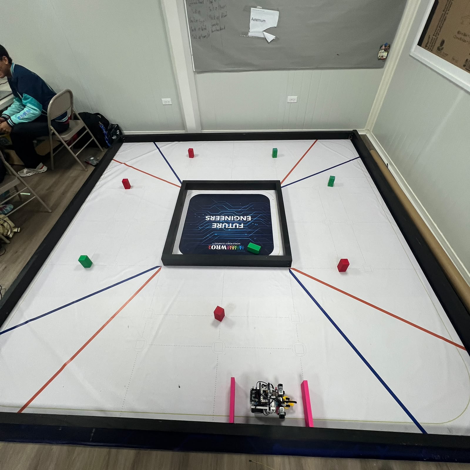 Figure 1.6. Full-course testing is the final integration step; individual subsystems are tested first to make failures easier to isolate.
The project uses progressive integration.
The preferred test order is:
```text
individual sensor
↓
individual motor
↓
straight driving
↓
single corner
↓
single obstacle
↓
obstacle recovery
↓
consecutive obstacles
↓
parking phases
↓
complete parking
↓
full course
```
This avoids using a complete run as the first test of a new subsystem.
For example, obstacle development begins with:
```text
one Red pillar
```
and:
```text
one Green pillar
```
before testing:
```text
Red → Green
Green → Red
multiple pillars
pillars near corners
```
Parking is similarly divided into:
```text
approach
entry
alignment
final movement
STOP
```
before testing it at the end of a complete run.
This progression makes each experiment more informative.
---
# 1.13 Evidence, Telemetry, and Version Control
A successful physical result is more useful when the team can determine **why** it worked.
For this reason, development versions increasingly expose telemetry such as:
```text
state
left ultrasonic
right ultrasonic
estimated geometry
Pixy target
target signature
required pass side
wall safety
steering request
final steering command
actual Motor B angle
course count
```
The desired engineering evidence chain is:
```text
VIDEO
+
TELEMETRY
+
SOFTWARE VERSION
+
TEST NOTES
```
Video shows:
```text
what happened physically
```
while telemetry shows:
```text
what the controller believed
```
and Git records:
```text
which software produced the behavior
```
This is stronger than relying on memory or filenames such as:
```text
final.py
final2.py
final_really_final.py
```
A known-good behavior should eventually correspond to a specific Git commit and documented robot configuration.
---
# 1.14 Major Engineering Decisions
The current Piolín architecture reflects several deliberate decisions made through testing.
| Engineering Question | Current Decision | Reasoning |
| :--- | :--- | :--- |
| One universal S1 configuration? | No | Gyro and Pixy solve different round-specific problems |
| Open S1 device | Gyro | Heading stabilization is highly useful for Open |
| Obstacle S1 device | Pixy2.1 | Forward color/object perception is required |
| Permanent front ultrasonic | No | Final architecture uses two lateral US sensors |
| S2 mapping | LEFT | Fixed physical identity |
| S3 mapping | RIGHT | Fixed physical identity |
| Direct camera-to-steering | No | Detection and navigation decisions are separated |
| Red/Green rule from image x? | No | Signature fixes competition passing side |
| Normal wall PID always active? | No | Authority changes according to state |
| Critical wall safety | Separate override | Safety must remain independent from navigation preference |
| First Pixy block automatically selected? | No | Target relevance is required |
| One missing camera frame releases target? | No | Temporary target memory is required |
| Parking from Pink alone? | No | Course state must first enable parking |
| Timed final parking movement only? | No | Encoder and physical geometry provide stronger evidence |
| Legacy prototypes deleted? | No | Preserved separately as engineering history |
These decisions are not independent.
Together they produce the current systems architecture.
---
# 1.15 Current Architecture as an Engineering Result
The current architecture can be summarized as:
```text
WRO COURSE
│
┌─────────────────┼─────────────────┐
│ │ │
▼ ▼ ▼
S4 S2 / S3 S1
floor state lateral geometry round-specific
│ │ │
│ │ ┌──────┴──────┐
│ │ │ │
│ │ ▼ ▼
│ │ GYRO PIXY2.1
│ │ Open Obstacles
│ │
└────────────┬────┴───────────────┐
│ │
▼ ▼
SENSOR PROCESSING PERCEPTION
│ │
└─────────┬──────────┘
▼
STATE MACHINE
│
┌──────────────────────┼──────────────────────┐
│ │ │
▼ ▼ ▼
WALL / COURSE OBSTACLE / CORNER PARKING
CONTROL CONTROL CONTROL
│ │ │
└──────────────────────┼──────────────────────┘
▼
CONTROL ARBITRATION
│
safety override
│
▼
STEERING TARGET
│
▼
MOTOR B
│
▼
ACKERMANN STEERING
MOTOR A
│
▼
PROPULSION
```
The important result is not only that the robot contains several sensors and controllers.
It is that each part has a defined responsibility and a defined relationship with the others.
---
# 1.16 Engineering Process Summary
Piolín's development process can be represented as a continuous loop:
```text
COMPETITION REQUIREMENT
│
▼
DEFINE PROBLEM
│
▼
BUILD / PROGRAM
│
▼
CONTROLLED TEST
│
▼
OBSERVE FAILURE
│
▼
FIND FIRST INCORRECT LAYER
│
┌────────────┼────────────┐
│ │ │
▼ ▼ ▼
HARDWARE SENSOR SOFTWARE
│ │ │
└────────────┼────────────┘
▼
FORM HYPOTHESIS
│
▼
CHANGE ONE MAIN CAUSE
│
▼
REPEAT TEST
│
┌─────────┴─────────┐
│ │
▼ ▼
BETTER WORSE
│ │
▼ ▼
VERIFY AGAIN REVERT
│
▼
SAVE BASELINE
│
▼
INTEGRATE SYSTEM
│
▼
FULL RUN
│
└──────────────► next problem
```
This loop has been applied repeatedly to:
```text
mechanical steering
ultrasonic placement
camera selection
color detection
wall navigation
corner handling
pillar avoidance
recovery
course counting
parking
```
---
# 1.17 Final Engineering Assessment
Piolín's current design should not be understood as the first architecture imagined by PiolínTech.
It is the result of repeated engineering decisions made after physical testing exposed limitations in earlier approaches.
Several major changes illustrate this process:
```text
earlier camera experiments
→ current direct Pixy2.1 Obstacle architecture
```
```text
different sensor configurations
→ two stable round-specific S1 configurations
```
```text
simple ultrasonic reactions
→ geometric lateral control + independent safety
```
```text
direct sensor-to-steering reactions
→ state-based software
```
```text
simultaneous controller influence
→ explicit control arbitration
```
```text
single sensor samples
→ confirmation, locking, and release
```
```text
timed assumptions
→ increased use of physical events and encoder progression
```
```text
whole-course trial-and-error
→ isolated subsystem testing followed by integration
```
The project also preserves the distinction between:
```text
CURRENT ARCHITECTURE
```
and:
```text
LEGACY DEVELOPMENT
```
because unsuccessful or replaced prototypes remain valuable evidence of the engineering process without being presented as part of the current robot.
The central systems-engineering principle used by PiolínTech is:
> **When Piolín fails, the objective is not to make the visible symptom disappear as quickly as possible. The objective is to identify which physical or software layer first became incorrect, change the smallest relevant part of the system, test the hypothesis repeatedly, and preserve the change only when the resulting improvement can be reproduced.**
This process has allowed PiolínTech to progressively transform individual mechanical, sensing, and software experiments into one integrated autonomous vehicle architecture while maintaining traceability between:
```text
problem
decision
implementation
test
result
next iteration
```
That traceability is a central part of Piolín's engineering documentation and of the team's approach to continued development.
---
### [← Back to PiolínTech Main README](../../README.md)