# Pixy2.1 Case — 3D Printing and Installation
This document describes the manufacturing, assembly, installation, and verification process for Piolín's custom **Pixy2.1 camera casing**.
The current casing is composed of two 3D-printed files:
```text
PIXY_Case1.stl
PIXY_Case2.stl
```
Together, these parts form the physical casing used around the Pixy2.1 camera during Piolín's **Obstacle Challenge configuration**.
The casing is not treated as a decorative component.
It is part of the camera installation because its geometry can influence:
```text
camera position
camera orientation
field of view
mechanical stability
amount of stray light reaching the camera
repeatability of visual detections
```
For this reason, every change to the casing or camera position must be followed by a vision-system verification.
---
## Component Overview
| Property | Current Implementation |
|---|---|
| Files | `PIXY_Case1.stl` + `PIXY_Case2.stl` |
| Component | Pixy2.1 camera casing |
| Vision sensor | Pixy2.1 |
| EV3 port | S1 during Obstacles |
| Communication | Direct Pixy2.1 connection to EV3 |
| Manufacturing method | FDM 3D printing |
| Printer | Anet ET4X |
| Material | OVERTURE High Speed PLA |
| Filament diameter | 1.75 mm |
| Nozzle temperature | 200 °C |
| Heated bed temperature | 80 °C |
| Print speed setting | 100% |
| Competition use | Obstacle Challenge |
| Status | Current |
During the Open Challenge, S1 is used by the EV3 Gyro Sensor instead.
Therefore:
```text
OPEN
S1 → Gyro
```
and:
```text
OBSTACLES
S1 → Pixy2.1
```
The Gyro Sensor and Pixy2.1 are not installed on S1 simultaneously in the current architecture.
---
# Why the Pixy Case Was Needed
The Pixy2.1 is one of the most important sensors in Piolín's Obstacle Challenge configuration.
It is responsible for identifying:
```text
sig1 → Pink → Parking
sig2 → Red → Pass RIGHT
sig3 → Green → Pass LEFT
```
The camera therefore needs a repeatable physical position.
If its position changes:
```text
CAMERA POSITION CHANGES
↓
IMAGE GEOMETRY CHANGES
↓
x / y / width / height CHANGE
↓
TARGET RELEVANCE CHANGES
↓
STEERING DECISIONS MAY CHANGE
```
A custom casing was introduced to provide a more controlled and repeatable camera installation.
The casing also provides physical protection and can partially reduce unwanted stray light depending on its geometry.
It does **not** make the Pixy2.1 immune to lighting variation.
Vision calibration is still required.
---
# Current Pixy2.1 Installation
The Pixy2.1 is mounted toward the front of Piolín during the Obstacle Challenge.
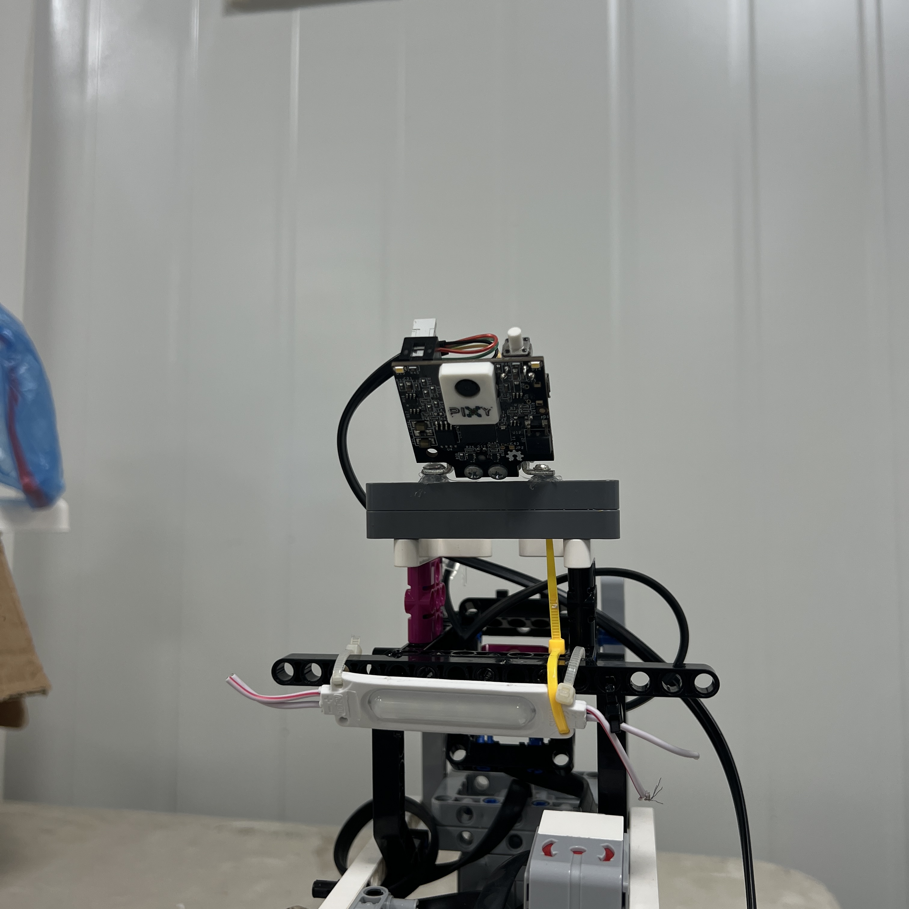 Figure 1. Front view of the Pixy2.1 used in Piolín's current Obstacle Challenge configuration.
The camera casing surrounds and supports the vision sensor while preserving the forward sensing area.
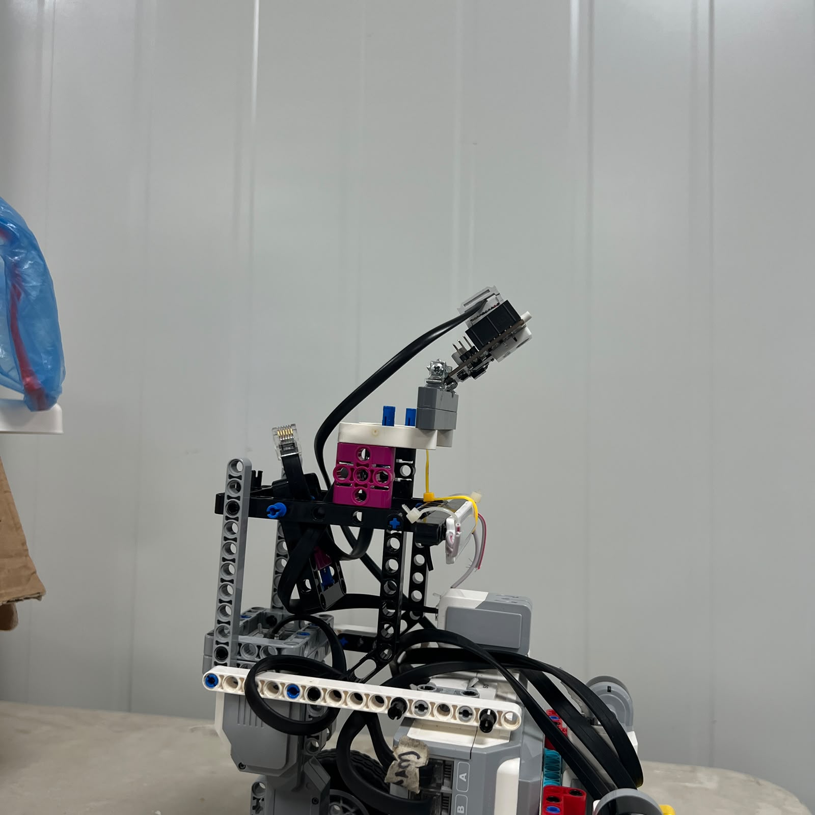 Figure 2. Side view of the Pixy2.1 installation.
A top view can also be used to inspect the relationship between the camera and the surrounding robot structure.
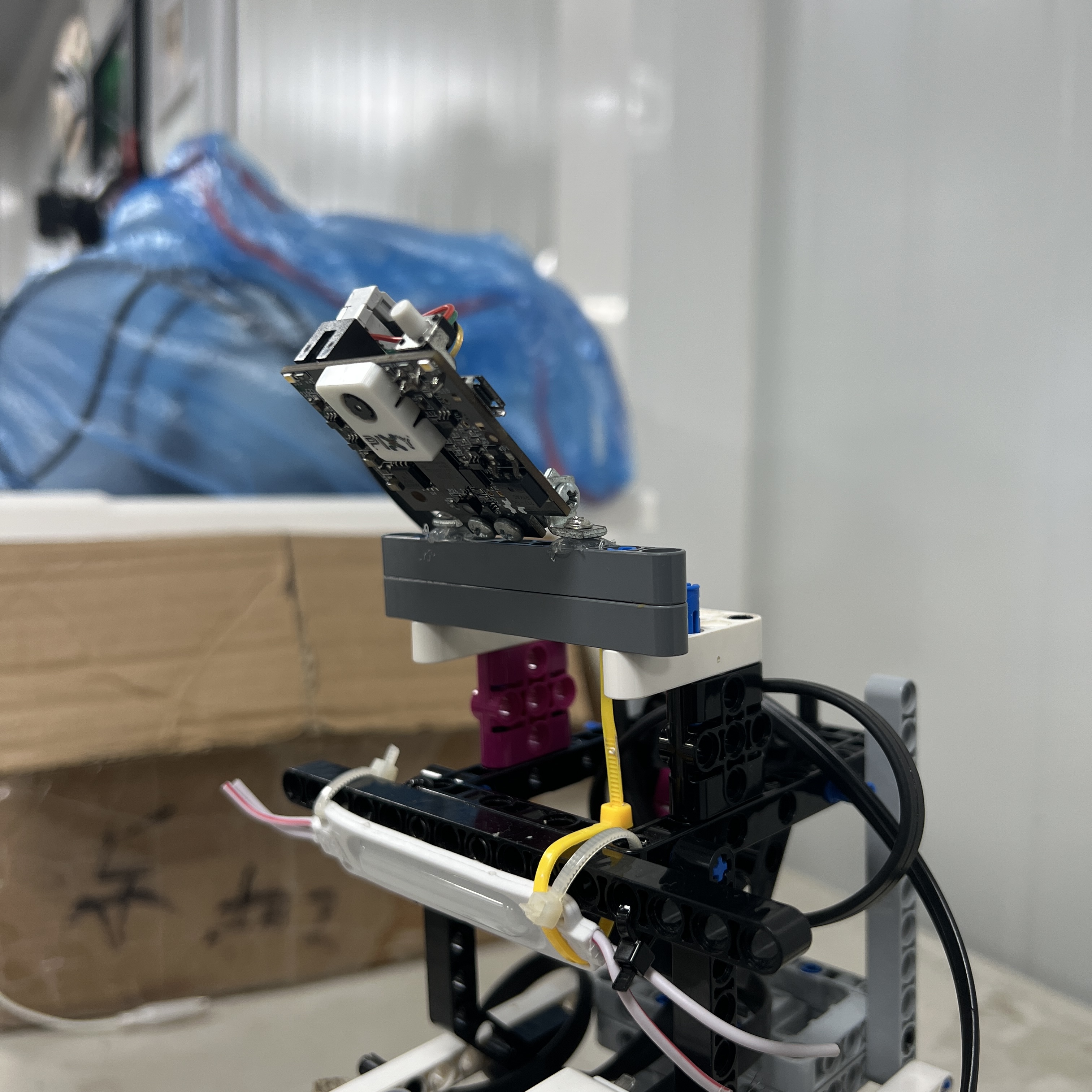 Figure 3. Top view of the Pixy2.1 installation and surrounding structure.
---
# Manufacturing Parameters
Both casing parts were produced using the same 3D-printing configuration.
| Parameter | Setting |
|---|---:|
| Printer | Anet ET4X |
| Material | OVERTURE High Speed PLA |
| Filament diameter | 1.75 mm |
| Nozzle temperature | 200 °C |
| Heated bed temperature | 80 °C |
| Print speed setting | 100% |
The `100%` speed value refers to the printer speed setting used during manufacturing.
It is not documented as a measured speed in mm/s.
Parameters that were not formally recorded, including exact:
```text
layer height
infill percentage
support configuration
print duration
```
are not presented as measured specifications.
---
# Printing Process
The complete manufacturing sequence is:
```text
PIXY_Case1.stl
+
PIXY_Case2.stl
↓
IMPORT INTO SLICER
↓
PREPARE BOTH PARTS
↓
SET PRINT PARAMETERS
↓
SLICE
↓
PREHEAT ANET ET4X
↓
BED → 80 °C
NOZZLE → 200 °C
↓
PRINT
↓
REMOVE PARTS
↓
INSPECT
↓
TEST PIXY FIT
↓
ASSEMBLE CASING
↓
INSTALL ON PIOLÍN
↓
VERIFY FIELD OF VIEW
↓
VERIFY COLOR SIGNATURES
↓
VALIDATE ON TRACK
```
Both pieces must work together as one camera-support assembly.
---
# Post-Print Inspection
After printing, both components are inspected before installation.
The checks include:
```text
Are both parts complete?
Is either part visibly deformed?
Does Pixy2.1 fit correctly?
Is the camera lens area unobstructed?
Are the connection points accessible?
Can the cable remain connected?
Does the casing interfere with nearby LEGO structure?
Can the assembly remain mechanically stable?
```
A successful print must satisfy both:
```text
MECHANICAL FIT
```
and:
```text
VISION COMPATIBILITY
```
A casing that physically fits but blocks part of the camera view is not considered a successful design.
---
# Assembly
The two STL files represent parts of the same camera casing:
```text
PIXY_Case1.stl
+
PIXY_Case2.stl
↓
PIXY2.1 CASING ASSEMBLY
```
The camera is placed within the casing so that the vision area remains exposed.
The assembly process must preserve:
```text
camera opening
camera orientation
cable access
mechanical support
```
The exact physical assembly method is determined by the final printed geometry and Piolín's current mounting configuration.
No unrecorded assembly dimensions or fastening specifications are presented as measured values.
---
# Installation on Piolín
After assembly, the casing is mounted on Piolín in the Obstacle Challenge configuration.
The current electrical architecture is:
```text
Pixy2.1
↓
S1
↓
EV3 Brick
```
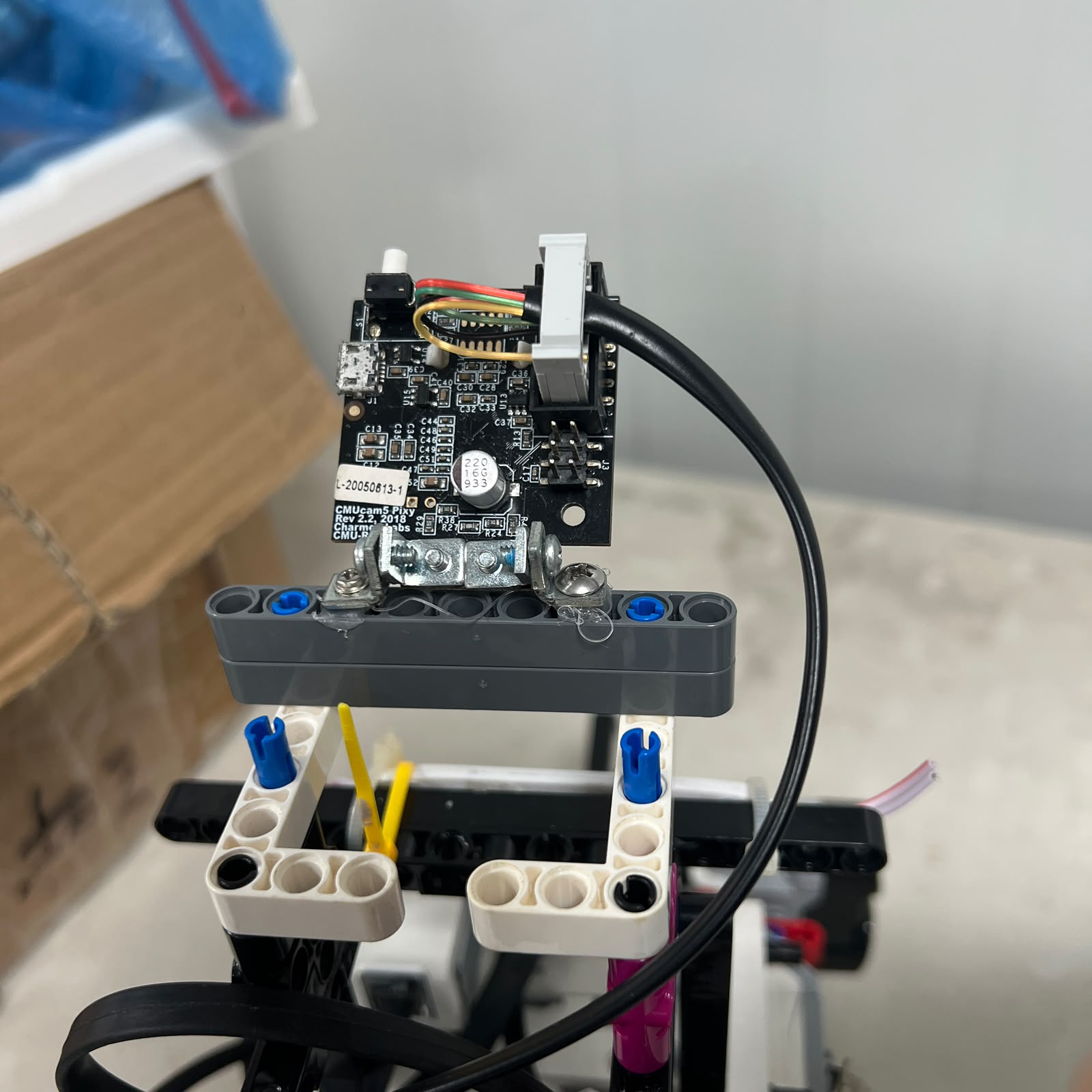 Figure 4. Pixy2.1 connection to EV3 sensor port S1 in the Obstacle Challenge configuration.
The current Pixy2.1 architecture uses a direct connection to the EV3.
Earlier HuskyLens and Arduino Nano configurations are legacy development architectures and are not part of this current camera installation.
---
# Installation Verification
Once mounted, the camera installation is checked before software tuning begins.
The verification sequence is:
```text
INSTALL CASING
↓
CHECK CAMERA FIT
↓
CHECK CAMERA OPENING
↓
CHECK CABLE
↓
CHECK CAMERA ORIENTATION
↓
POWER PIXY2.1
↓
VERIFY EV3 COMMUNICATION
↓
TEST COLOR SIGNATURES
```
The team checks that the casing does not:
```text
block the camera
cover the lens
interfere with S1 connection
force the camera into an unusable orientation
move excessively during robot motion
```
---
# Effect on Vision Geometry
The casing is part of the complete vision system because Pixy2.1 produces geometric information about detected objects.
Useful block data includes:
```text
signature
x
y
width
height
```
The physical camera installation affects how those values appear.
For example:
```text
CAMERA MOVED UP / DOWN
→ apparent y and size can change
```
```text
CAMERA ROTATED
→ target positions inside image can change
```
```text
CAMERA MOVED SIDEWAYS
→ apparent x can change
```
Therefore:
> **Pixy calibration should always be performed using the same physical camera installation that will be used during competition.**
---
# Red Pillar Verification
The Red obstacle signature is:
```text
sig2
→ RED
→ PASS RIGHT
```
After the casing is installed, Red detection is tested again.
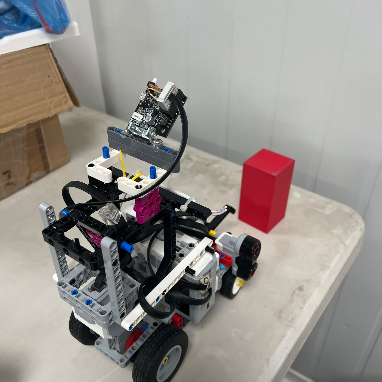 Figure 5. Pixy2.1 Red-pillar detection used to verify the installed camera system.
The test verifies that the installed camera can still provide a usable Red block to the perception system.
The camera's image position does not determine the competition passing side.
The rule remains:
```text
RED
→ RIGHT
```
regardless of whether the Red block appears on the left, center, or right side of the image.
---
# Green Pillar Verification
The Green signature is:
```text
sig3
→ GREEN
→ PASS LEFT
```
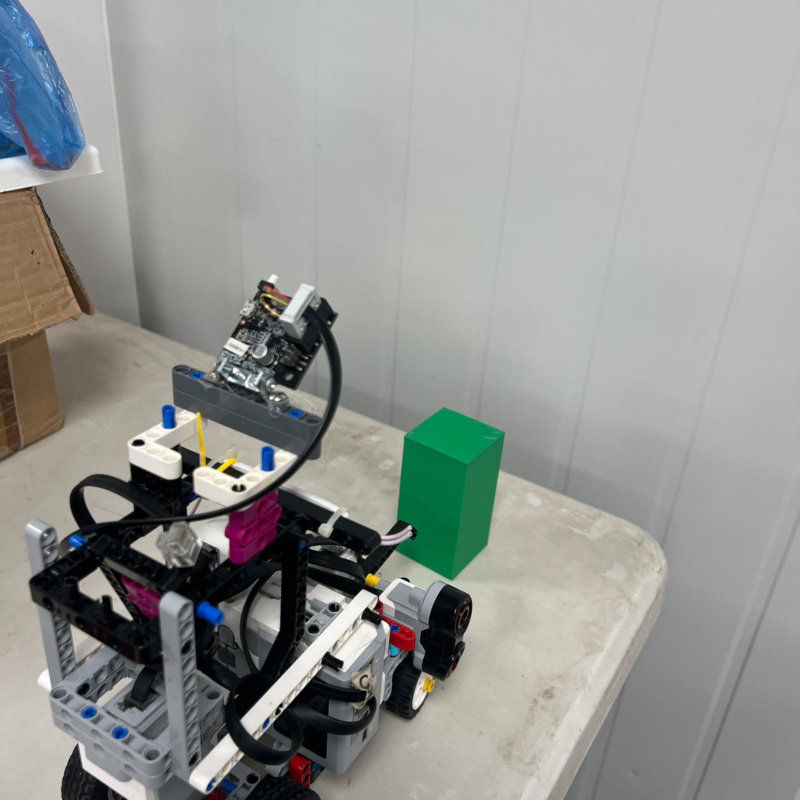 Figure 6. Pixy2.1 Green-pillar detection used to verify the installed camera system.
The fixed navigation rule is:
```text
GREEN
→ LEFT
```
The camera's `x` coordinate may influence the magnitude or geometry of the maneuver, but it does not redefine which side of the pillar Piolín must use.
---
# Pink Parking Verification
The parking signature is:
```text
sig1
→ PINK
→ Parking reference
```
The Pink reference is also tested after installation.
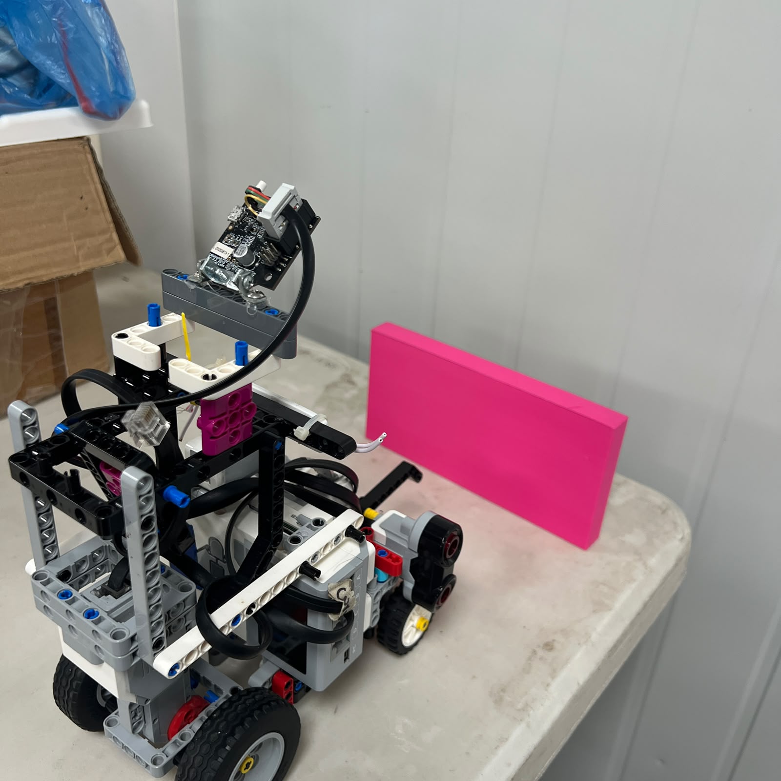 Figure 7. Pixy2.1 detection of the Pink parking reference after camera installation.
The camera must be able to provide useful Pink observations for the parking perception system.
However:
```text
PINK DETECTED
≠
IMMEDIATE PARKING
```
The navigation architecture also requires:
```text
course progression complete
+
Pink confirmation
+
parking eligibility
```
before the parking maneuver begins.
---
# Recalibration After Installation
Installing or modifying the Pixy casing may affect the vision geometry.
For that reason, the correct process is:
```text
PRINT
↓
ASSEMBLE
↓
INSTALL
↓
VERIFY CAMERA POSITION
↓
TEST RED
↓
TEST GREEN
↓
TEST PINK
↓
OBSERVE x / y / width / height
↓
ADJUST SOFTWARE THRESHOLDS IF REQUIRED
↓
TEST WHILE MOVING
```
The previous calibration should not automatically be assumed valid after a significant physical change.
---
# Relationship with Vision Processing
The printed casing supports the physical camera layer.
It does not make navigation decisions.
The complete information path is:
```text
PHYSICAL PILLAR
↓
PIXY2.1 + CASING
↓
RAW PIXY BLOCKS
↓
VALIDATION
↓
CANDIDATE SELECTION
↓
CONFIRMATION
↓
TARGET LOCK
↓
NAVIGATION STATE MACHINE
↓
OBSTACLE CONTROLLER
↓
CONTROL ARBITRATION
↓
MOTOR B
```
The detailed Pixy processing architecture is documented in:
[Pixy2.1 Vision Processing Flowchart](../../embed/02_VProcessing.md)
The detailed pillar maneuver is documented in:
[Obstacle Strategy Flowchart](../../embed/05_ObstacleStrategyFC.md)
The overall control hierarchy is documented in:
[Control Arbitration Flowchart](../../embed/04_ControlArbitration.md)
---
# Engineering Iteration
The Pixy casing is part of PiolínTech's sensor-development process.
The architecture evolved through multiple vision approaches before reaching the current direct Pixy2.1 configuration.
The current physical workflow is:
```text
VISION REQUIREMENT
↓
CAMERA SELECTION
↓
PHYSICAL MOUNTING
↓
3D-PRINTED CASING
↓
FIT TEST
↓
VISION TEST
↓
SOFTWARE CALIBRATION
↓
TRACK VALIDATION
```
This illustrates the relationship between:
```text
MECHANICAL DESIGN
ELECTRONICS
PERCEPTION
SOFTWARE CONTROL
```
A camera algorithm cannot be calibrated independently from the physical camera installation.
---
# Reproduction Procedure
To reproduce the current Pixy2.1 casing:
### Required files
```text
PIXY_Case1.stl
PIXY_Case2.stl
```
### Printer
```text
Anet ET4X
```
### Material
```text
OVERTURE High Speed PLA
1.75 mm
```
### Printing configuration
```text
Nozzle temperature:
200 °C
Heated bed:
80 °C
Print speed setting:
100%
```
### Post-print procedure
```text
1. Inspect both printed components.
2. Verify that Pixy2.1 fits inside the casing.
3. Confirm that the camera opening remains unobstructed.
4. Confirm that cable access remains available.
5. Assemble the two casing components.
6. Install the Pixy2.1 assembly on Piolín.
7. Connect Pixy2.1 to S1.
8. Verify communication with the EV3.
9. Verify Red / sig2 detection.
10. Verify Green / sig3 detection.
11. Verify Pink / sig1 detection.
12. Inspect x, y, width, and height behavior.
13. Recalibrate perception thresholds if required.
14. Test detection while Piolín is moving.
15. Validate the installation during obstacle maneuvers.
```
---
# Reproduction Checklist
| Check | Expected Result |
|---|---|
| `PIXY_Case1.stl` printed | Complete physical part |
| `PIXY_Case2.stl` printed | Complete physical part |
| Pixy fits casing | Camera can be installed |
| Camera opening clear | Lens/FOV not physically blocked |
| Cable accessible | S1 connection possible |
| Assembly stable | Camera position remains repeatable |
| Pixy powers and communicates | EV3 receives camera information |
| `sig2` detected | Red pillar can be identified |
| `sig3` detected | Green pillar can be identified |
| `sig1` detected | Pink parking reference can be identified |
| Track testing completed | Installation works under robot motion |
---
# System Relationship
The role of the printed casing can be summarized as:
```text
PIXY_Case1.stl
+
PIXY_Case2.stl
↓
PHYSICAL CAMERA CASING
↓
REPEATABLE PIXY INSTALLATION
↓
MORE CONSISTENT IMAGE GEOMETRY
↓
TARGET VALIDATION
↓
OBSTACLE / PARKING PERCEPTION
↓
AUTONOMOUS CONTROL
```
This is why the casing is considered part of the vision architecture rather than only a mechanical accessory.
---
# Engineering Summary
The Pixy2.1 casing demonstrates how a mechanical component can directly support software reliability.
PiolínTech's complete reasoning chain is:
```text
VISION NEEDS REPEATABLE INPUT
↓
CAMERA NEEDS REPEATABLE POSITION
↓
CUSTOM CASING IS DESIGNED
↓
CASING IS 3D PRINTED
↓
PIXY2.1 IS INSTALLED
↓
SIGNATURES ARE VERIFIED
↓
IMAGE GEOMETRY IS CHECKED
↓
SOFTWARE IS RECALIBRATED
↓
FULL OBSTACLE TESTING
```
The central design principle is:
> **The Pixy2.1 casing is considered successful only when it provides a stable physical camera installation without obstructing vision, and when Red, Green, and Pink detections remain reliable after the completed assembly is installed on Piolín.**
---
### [← Back to 3D Printing Process](PrintingProcess.md)