# Phase 4 — Current Competition Architecture
## 1. Current Generation of Piolín
Phase 4 represents the **current competition architecture of Piolín** for WRO Future Engineers 2026.
Unlike the earlier development phases, Phase 4 is not centered on testing as many hardware combinations as possible.
Its objective is to consolidate the lessons obtained from previous prototypes into a simpler, more clearly defined autonomous vehicle architecture.
The development progression can be summarized as:
```text
PHASE 1
Initial EV3 Prototype
↓
PHASE 2
Mechanical + Navigation Development
↓
PHASE 3
Sensor + Vision + Control Experimentation
↓
PHASE 4
CURRENT COMPETITION ARCHITECTURE
```
The main Phase 4 principle is:
> **Each component must have a clear responsibility, and each competition round should use only the sensing information that is useful for that task.**
Phase 4 therefore keeps the LEGO MINDSTORMS EV3 as the central controller while refining the mechanical, sensing, perception, and software systems around it.
---
## 2. Current Piolín Platform
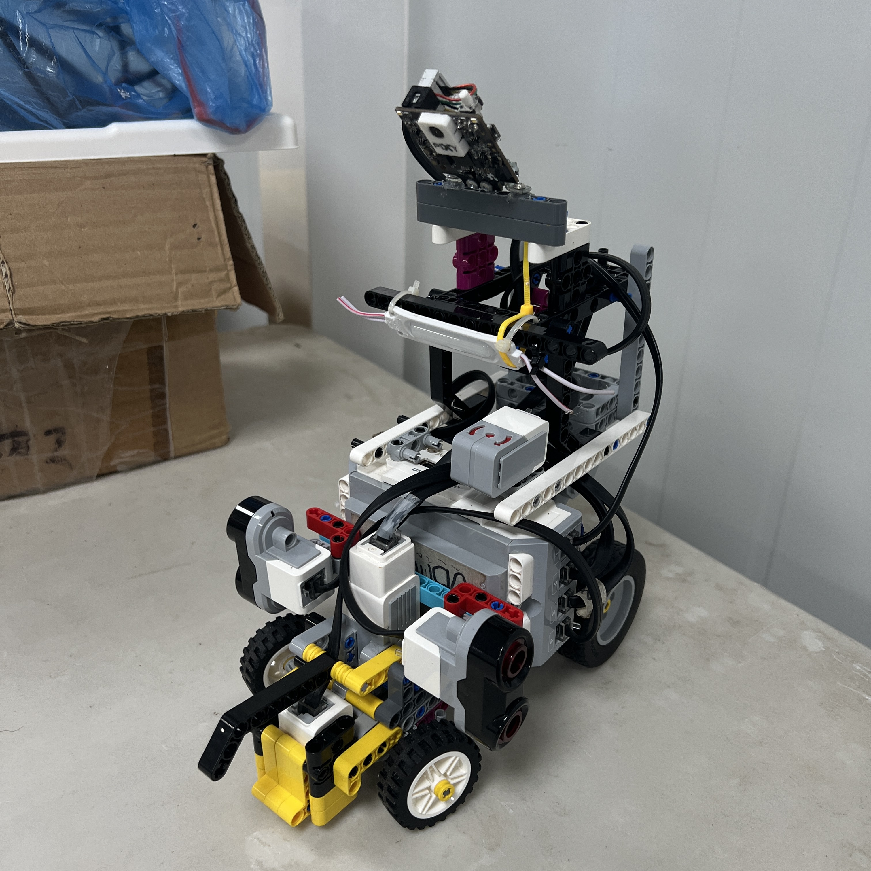 Figure 1. Piolín in its current Open Challenge configuration.
The current robot uses a car-like vehicle architecture with:
```text
rear propulsion
front Ackermann steering
two lateral ultrasonic sensors
downward floor sensing
round-specific S1 sensing
```
The same mechanical platform is used for both competition rounds.
What changes is the sensor connected to:
```text
S1
```
---
# 3. Phase 4 Architecture at a Glance
The common hardware architecture is:
```text
EV3 BRICK
│
┌────────────────┼────────────────┐
│ │ │
▼ ▼ ▼
MOTOR A MOTOR B SENSORS
PROPULSION STEERING │
│ │ │
▼ ▼ ┌────────┼────────┐
REAR DRIVETRAIN ACKERMANN │ │ │
S2 S3 S4
LEFT RIGHT COLOR
US US
```
S1 changes according to the competition round:
```text
OPEN
S1 → EV3 Gyro Sensor
```
```text
OBSTACLES
S1 → Pixy2.1
```
The current system does **not** install the Gyro Sensor and Pixy2.1 simultaneously.
This round-specific configuration became one of the most important architecture decisions of Phase 4.
---
# 4. Current Mechanical Architecture
Phase 4 preserves and refines the vehicle concepts developed during Phase 2 and tested throughout Phase 3.
The current primary mechanical roles are:
| System | Current Component | Role |
|---|---|---|
| Main controller | LEGO MINDSTORMS EV3 Brick | Central autonomous control |
| Propulsion | EV3 Large Motor — Motor A | Rear-wheel propulsion |
| Steering | EV3 Medium Motor — Motor B | Front steering |
| Steering geometry | Ackermann-style mechanism | Car-like turning geometry |
| Left distance sensing | EV3 Ultrasonic Sensor — S2 | Left lateral geometry |
| Right distance sensing | EV3 Ultrasonic Sensor — S3 | Right lateral geometry |
| Floor sensing | EV3 Color Sensor — S4 | Blue/Orange course landmarks |
| Open orientation | EV3 Gyro Sensor — S1 | Heading and rotation information |
| Obstacle vision | Pixy2.1 — S1 | Red/Green/Pink visual perception |
| Power | EV3 Rechargeable Battery 45501 | Main robot power |
Only Pixy2.1 is outside the standard LEGO MINDSTORMS EV3 sensing ecosystem.
---
# 5. Ackermann Steering as the Permanent Steering Architecture
Ackermann steering remained one of the strongest mechanical decisions from the earlier phases.
The current architecture separates:
```text
PROPULSION
→ Motor A
```
from:
```text
STEERING
→ Motor B
```
Motor B controls the front steering mechanism.
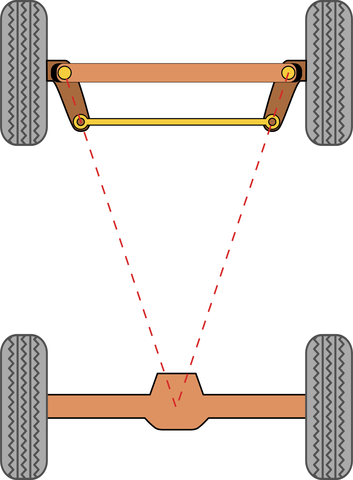 Figure 2. Piolín's current Ackermann steering architecture.
The objective is to allow Piolín to follow vehicle-like curved trajectories rather than relying on skid steering.
The mechanical and software systems must therefore work together.
```text
MOTOR B TARGET
↓
STEERING LINKAGE
↓
FRONT WHEEL ANGLES
↓
TURNING CURVATURE
↓
VEHICLE TRAJECTORY
```
This means that software cannot treat Piolín as a robot capable of rotating freely around its center.
Turning requires forward or backward vehicle progression.
---
# 6. Permanent Lateral Ultrasonic Architecture
Phase 3 involved several ultrasonic configurations.
Phase 4 simplified them to two permanent lateral sensors.
The fixed identity is:
```text
S2
→ LEFT Ultrasonic Sensor
```
```text
S3
→ RIGHT Ultrasonic Sensor
```
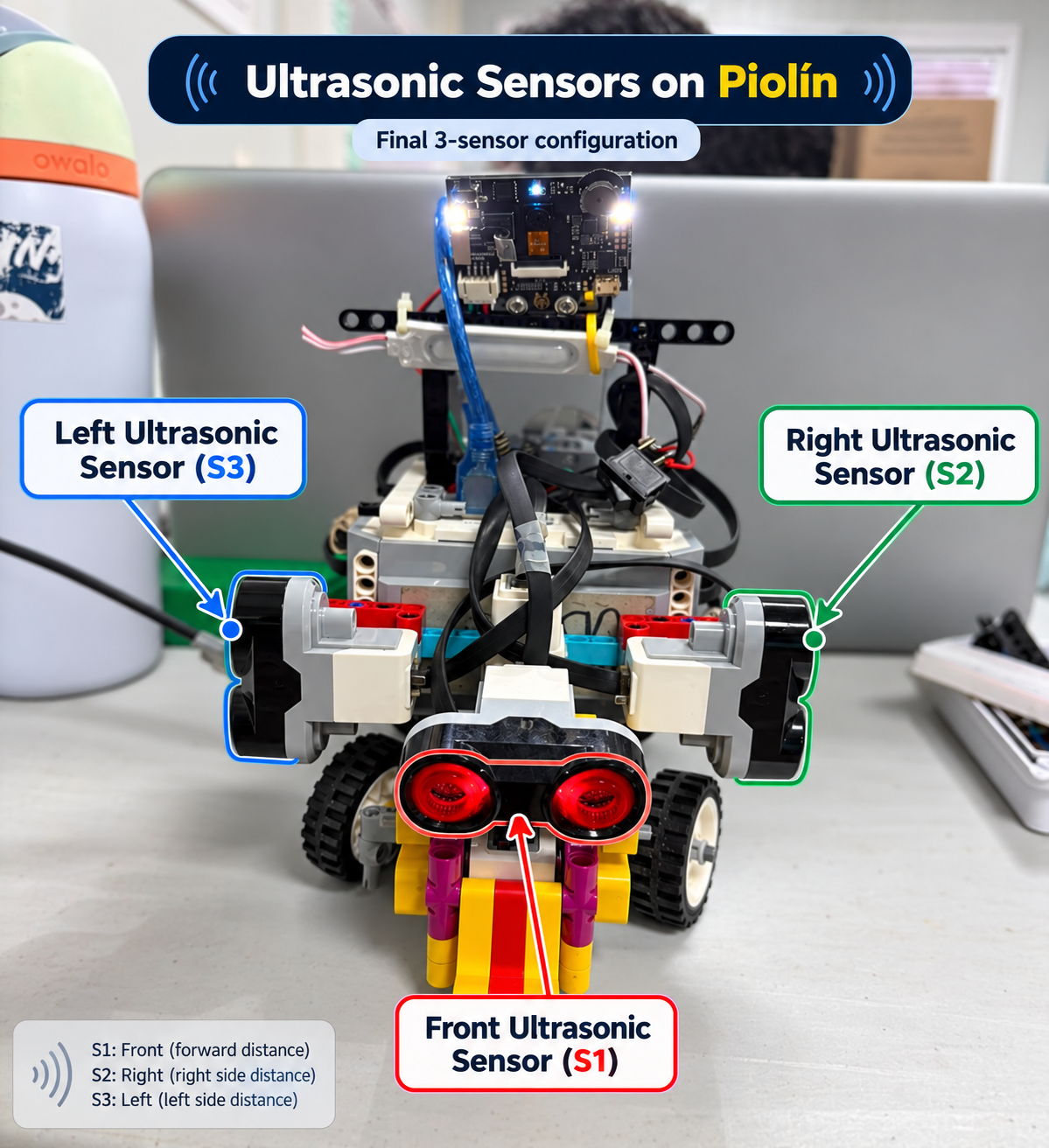 Figure 3. Permanent Phase 4 ultrasonic convention: S2 = LEFT and S3 = RIGHT.
This convention does not change when Piolín changes direction around the track.
Instead, the software determines which sensor currently represents:
```text
inner side
```
or:
```text
outer side
```
according to course direction.
For counterclockwise navigation:
```text
S2 LEFT
→ inner side
S3 RIGHT
→ outer side
```
For clockwise navigation:
```text
S3 RIGHT
→ inner side
S2 LEFT
→ outer side
```
This keeps the hardware naming physically consistent while allowing the navigation meaning to change with course direction.
---
# 7. Open Challenge Configuration
During the Open Challenge, Piolín uses:
```text
S1 → Gyro
S2 → LEFT Ultrasonic
S3 → RIGHT Ultrasonic
S4 → Color Sensor
```
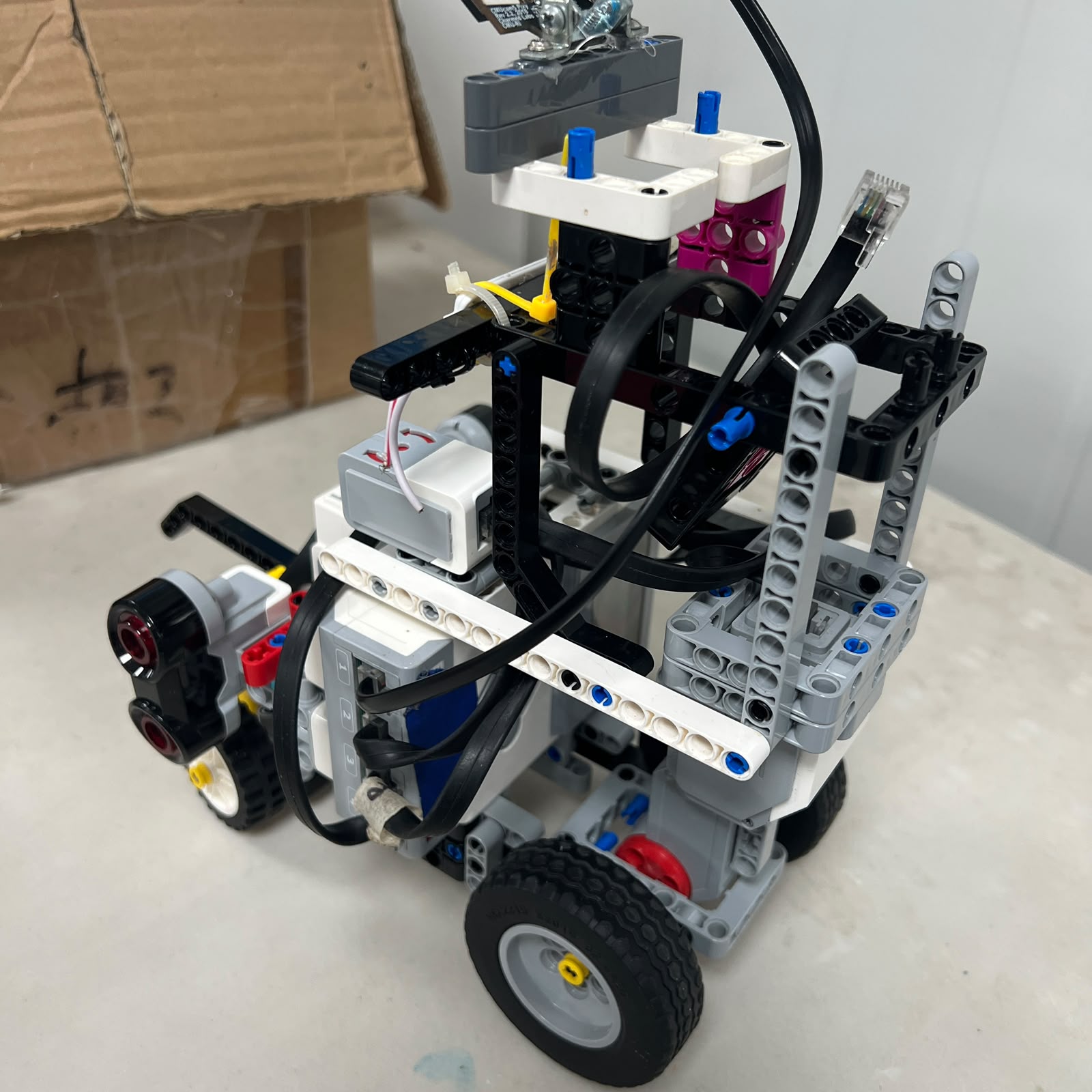 Figure 4. Current Open Challenge sensor configuration.
The Open architecture separates three major types of information.
### Lateral geometry
```text
S2 + S3
→ relationship with the course boundaries
```
### Orientation
```text
Gyro
→ heading and rotation
```
### Course landmarks
```text
S4
→ Blue / Orange floor events
```
The architecture can therefore be represented as:
```text
OPEN COURSE
│
┌────────────┼────────────┐
│ │ │
▼ ▼ ▼
S2/S3 S4 GYRO
│ │ │
▼ ▼ ▼
GEOMETRY EVENTS HEADING
│ │ │
└────────────┼────────────┘
▼
NAVIGATION LOGIC
│
┌──────┴──────┐
▼ ▼
MOTOR A MOTOR B
```
---
## Open Direction Detection
S4 provides the initial course-direction landmark.
The current rule is:
```text
FIRST BLUE
→ COUNTERCLOCKWISE
```
and:
```text
FIRST ORANGE
→ CLOCKWISE
```
Once established, direction is not repeatedly redefined by every later floor marking.
Later events contribute to:
```text
course progression
corner context
lap progression
parking eligibility
```
---
## Open Geometry Control
The Open controller increasingly relies on the combination of:
```text
lateral ultrasonic geometry
+
gyro heading
```
rather than asking one sensor to solve both problems.
Conceptually:
```text
S2 + S3
→ Where am I laterally?
```
```text
GYRO
→ Which direction is the chassis pointing?
```
These two types of error are related but not identical.
Separating them allows the software to distinguish:
```text
lateral displacement
```
from:
```text
heading drift
```
more effectively.
---
## Open Corner Handling
Corners require a temporary change in control assumptions.
During a straight section:
```text
S2/S3
→ relatively stable corridor geometry
```
During a corner:
```text
vehicle rotates
↓
sensor beams rotate
↓
observed wall geometry changes
```
The Gyro Sensor therefore contributes to confirming vehicle rotation while the lateral sensors are used again after the new corridor becomes visible.
The intended sequence is:
```text
STRAIGHT
↓
COURSE / FLOOR EVIDENCE
↓
CORNER
↓
GYRO ROTATION
↓
NEW LATERAL GEOMETRY
↓
STABILIZE
↓
STRAIGHT
```
This represents a significant improvement over purely timed turning.
---
# 8. Obstacle Challenge Configuration
During the Obstacle Challenge, S1 changes.
The current architecture is:
```text
S1 → Pixy2.1
S2 → LEFT Ultrasonic
S3 → RIGHT Ultrasonic
S4 → Color Sensor
```
There is:
```text
NO GYRO
```
in this configuration.
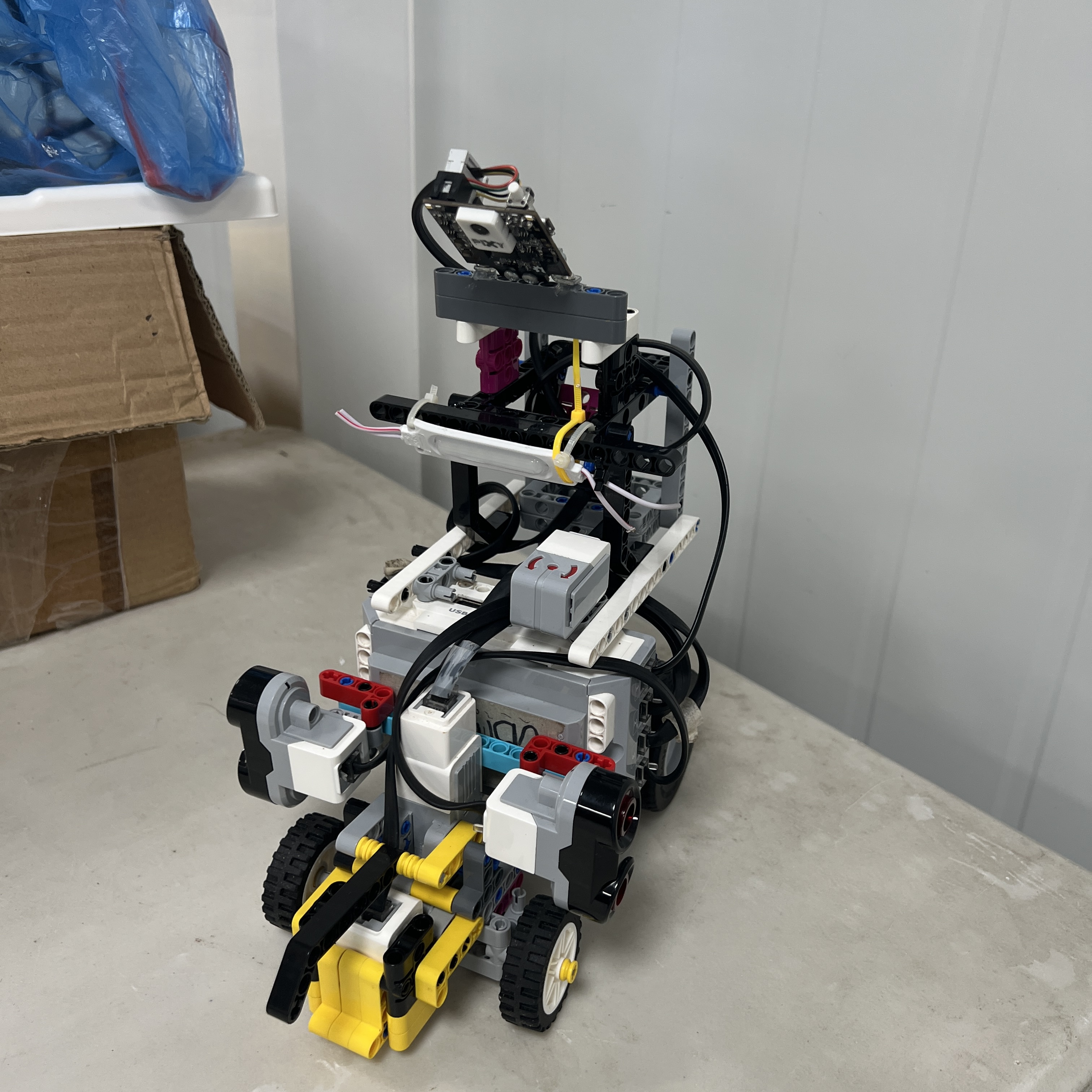 Figure 5. Piolín in its current Obstacle Challenge configuration with Pixy2.1.
The wiring configuration is:
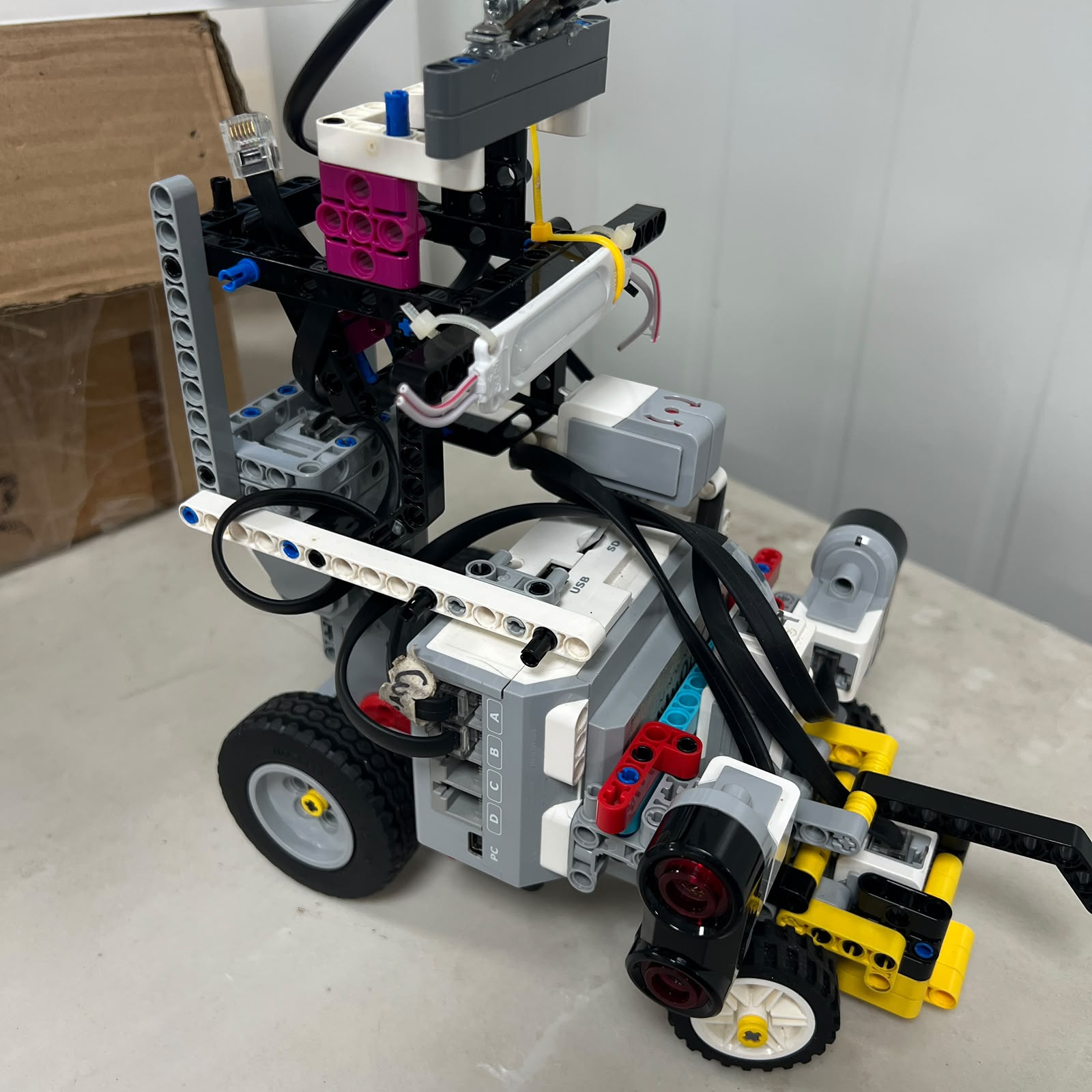 Figure 6. Current Obstacle Challenge sensor configuration.
The architectural change is deliberate.
Open requires strong orientation information.
Obstacles requires visual object identity.
Therefore:
```text
OPEN
needs HEADING
→ Gyro
```
while:
```text
OBSTACLES
needs VISUAL IDENTITY
→ Pixy2.1
```
---
# 9. Direct Pixy2.1 Integration
An important Phase 4 simplification was the selection of Pixy2.1 as the current obstacle vision sensor.
The current architecture is:
```text
PIXY2.1
↓
EV3 S1
↓
EV3 SOFTWARE
```
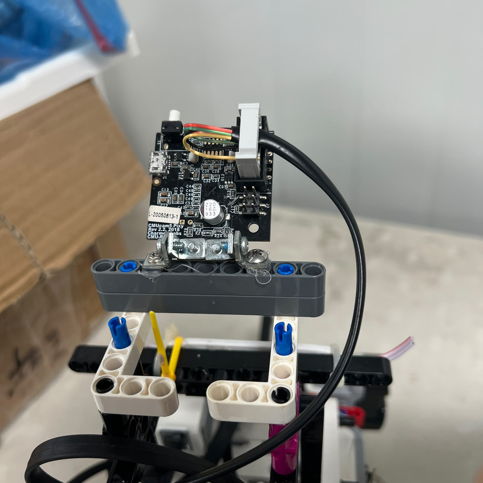 Figure 7. Pixy2.1 connected directly to S1 in Piolín's current Obstacle Challenge architecture.
This replaced the earlier development architecture involving:
```text
HuskyLens
+
Arduino Nano
+
EV3
```
which is now preserved as legacy engineering material.
The Phase 4 objective is:
```text
reduce unnecessary communication layers
```
while keeping the vision system capable of providing the information required by the obstacle software.
---
# 10. Current Vision Roles
Pixy2.1 uses color signatures to identify relevant competition objects.
The current signature mapping is:
```text
sig1
→ PINK
→ Parking
```
```text
sig2
→ RED
→ PASS RIGHT
```
```text
sig3
→ GREEN
→ PASS LEFT
```
Useful visual data includes:
```text
signature
x
y
width
height
```
The responsibilities are intentionally separated.
```text
SIGNATURE
→ object identity
→ WRO passing rule
```
while:
```text
x / y / width / height
→ target geometry and relevance
```
The position of a pillar inside the image does not redefine the competition passing rule.
Therefore:
```text
RED
→ RIGHT
```
and:
```text
GREEN
→ LEFT
```
regardless of whether the detected block currently appears on the left or right side of the image.
---
# 11. From Vision Reaction to Vision Processing
One of the strongest Phase 4 software changes is that the camera is no longer treated as a direct steering controller.
The desired processing chain is:
```text
PIXY BLOCKS
↓
VALIDATE
↓
BUILD CANDIDATES
↓
SELECT RELEVANT TARGET
↓
CONFIRM
↓
LOCK
↓
STATE MACHINE
↓
OBSTACLE CONTROLLER
↓
CONTROL ARBITRATION
↓
MOTOR B
```
This is fundamentally different from:
```text
camera sees Red
→ instantly steer
```
The camera provides evidence.
The software determines what that evidence means in the current physical context.
---
# 12. State-Based Navigation
Phase 4 introduces a clearer separation between different physical objectives.
The intended Obstacle Challenge state structure includes:
```text
START / ACQUIRE
NORMAL
TARGET_ACQUIRE
AVOID
PASS_CONFIRM
RECOVER
CORNER
PARKING
STOP
```
Each state answers:
> **What physical objective is Piolín trying to complete right now?**
For example:
```text
NORMAL
→ maintain useful track geometry
```
```text
TARGET_ACQUIRE
→ verify a possible obstacle
```
```text
AVOID
→ execute the required pillar trajectory
```
```text
PASS_CONFIRM
→ verify physical clearance
```
```text
RECOVER
→ restore useful track geometry
```
```text
PARKING
→ construct final parking pose
```
This structure prevents every behavior from operating with equal authority at the same time.
---
# 13. Control Arbitration
Phase 3 demonstrated that multiple controllers could fight for Motor B.
Phase 4 addresses this explicitly through control arbitration.
The intended priority is:
```text
1. CRITICAL SAFETY
2. ACTIVE MANEUVER
3. NORMAL NAVIGATION
```
This means Piolín does not calculate steering as an unrestricted sum such as:
```text
wall
+
pillar
+
corner
+
recovery
```
Instead:
```text
CURRENT STATE
↓
SELECT PRIMARY CONTROLLER
↓
CHECK CRITICAL SAFETY
↓
ONE FINAL STEERING COMMAND
↓
MOTOR B
```
This is especially important during obstacle avoidance.
For example:
```text
RED pillar
→ obstacle controller requires RIGHT
```
while normal wall geometry may temporarily prefer:
```text
LEFT
```
During `AVOID`, the obstacle trajectory must remain the primary maneuver while wall sensing acts mainly as physical context and critical safety.
---
# 14. Pillar Handling as a Complete Maneuver
Phase 4 does not define obstacle avoidance as simply turning around a pillar.
The full intended process is:
```text
DETECT
↓
VALIDATE
↓
SELECT
↓
CONFIRM
↓
LOCK
↓
AVOID
↓
PASS_CONFIRM
↓
RELEASE
↓
RECOVER
↓
NORMAL
```
This solves several problems observed during Phase 3.
### Temporary visual loss
```text
pillar disappears from Pixy
≠
pillar has been passed
```
### Correct detection but wrong maneuver
```text
correct Red classification
≠
guaranteed Right physical trajectory
```
### Successful pass but poor next position
```text
pillar cleared
≠
robot ready for next obstacle
```
The maneuver is considered complete only after Piolín has also recovered toward useful course geometry.
---
# 15. S4 Event-Based Course Processing
The downward EV3 Color Sensor remains connected to:
```text
S4
```
Phase 4 treats Blue and Orange markings as **physical course events** rather than raw loop readings.
The event lifecycle is:
```text
CLASSIFY
↓
CANDIDATE
↓
CONFIRM
↓
ACCEPT
↓
LATCH
↓
COUNT ONCE
↓
WAIT FOR NEUTRAL
↓
RELEASE
↓
RE-ARM
```
The objective is:
```text
ONE PHYSICAL MARKING
→ ONE SOFTWARE EVENT
```
This prevents a single marking from being counted repeatedly while the sensor remains over it.
Course events contribute to:
```text
direction
progression
corner context
parking eligibility
```
---
# 16. 3D-Printed Sensor Components
Phase 4 also introduces custom 3D-printed components as part of the sensing architecture.
The current files are:
```text
ColorSensorCasing.stl
PIXY_Case1.stl
PIXY_Case2.stl
```
### Color Sensor casing
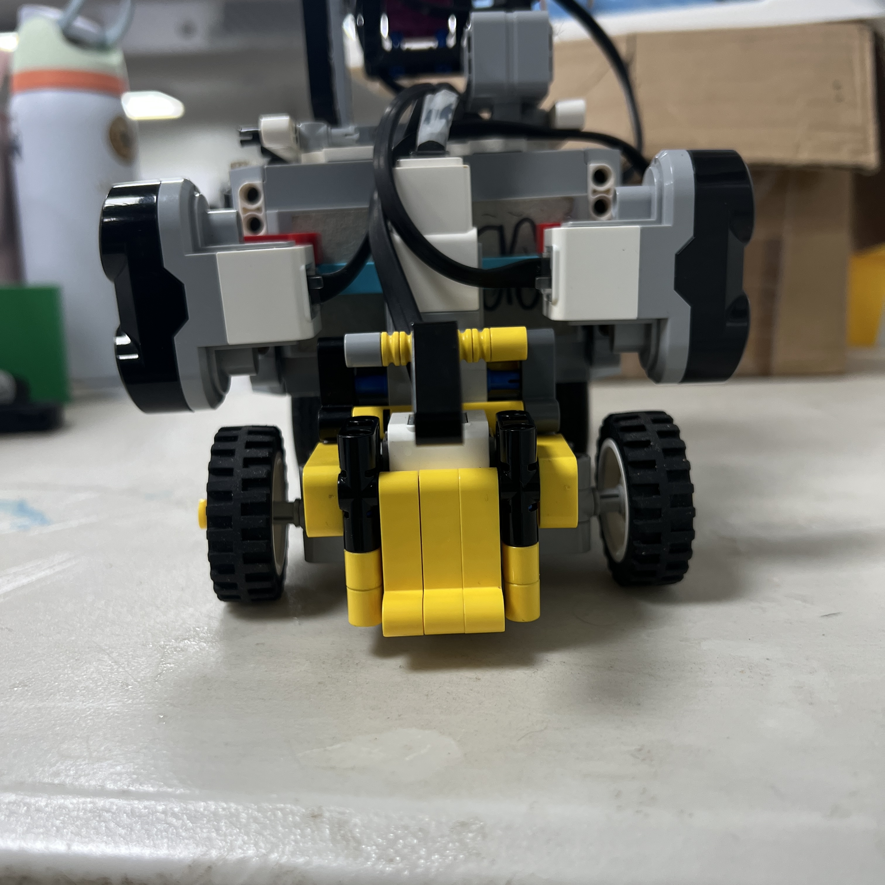 Figure 8. Current 3D-printed casing used around Piolín's S4 Color Sensor.
The casing creates a more controlled physical environment around S4 and helps reduce the influence of uncontrolled ambient light.
Because it changes the optical environment, S4 is tested again after installation.
---
### Pixy2.1 casing
The Pixy2.1 uses a custom two-part casing created from:
```text
PIXY_Case1.stl
PIXY_Case2.stl
```
The casing provides:
```text
mechanical support
camera protection
more repeatable installation
partial stray-light shielding depending on geometry
```
Changing the physical camera installation may also change:
```text
x
y
width
height
```
of detected blocks.
Therefore:
```text
PRINT
→ INSTALL
→ VERIFY
→ RECALIBRATE IF REQUIRED
```
is part of the vision-development process.
---
# 17. Parking Becomes a Dedicated Subsystem
Parking is no longer treated simply as:
```text
turn
→ drive for time
→ stop
```
Phase 4 defines a dedicated parking progression.
The intended Obstacle Challenge sequence is:
```text
COURSE COMPLETE
↓
PARKING ELIGIBLE
↓
PINK sig1 CONFIRMED
↓
APPROACH
↓
ENTRY
↓
ALIGN
↓
FINAL
↓
STOP
```
Parking can combine:
```text
Pixy visual information
S2/S3 geometry
Motor A encoder progression
Motor B steering position
```
The parking subsystem is still under active calibration.
For this reason, current development values are treated as calibration parameters rather than as final measured competition specifications.
---
# 18. Round-Specific Software Environments
Phase 4 also keeps the software configurations separated.
### Open Challenge
The current Open development architecture uses:
```text
Pybricks MicroPython
```
with:
```text
Gyro
S2/S3 ultrasonic geometry
S4 floor sensing
Motor A
Motor B
```
### Obstacle Challenge
The Obstacle Challenge vision architecture uses:
```text
ev3dev2
SMBus / I2C
```
for direct Pixy2.1 communication and obstacle development.
The two environments are not intentionally mixed inside one runtime file.
This separation makes each round easier to:
```text
debug
test
reproduce
maintain
```
---
# 19. Power Architecture
Piolín continues to use the official:
```text
LEGO MINDSTORMS EV3
Rechargeable DC Battery
Model 45501
```
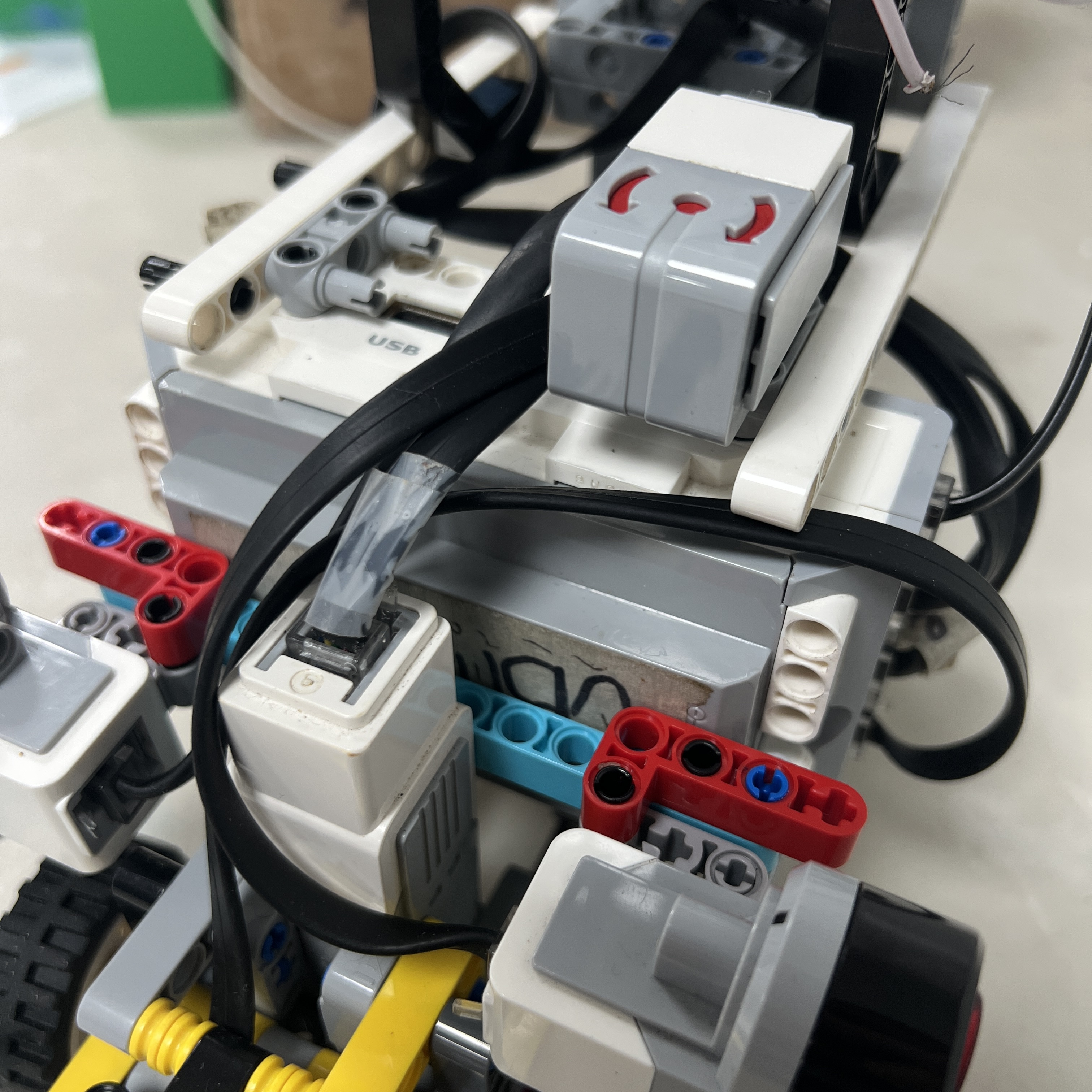 Figure 9. EV3 Rechargeable DC Battery 45501 used as Piolín's main power source.
The current robot does not require:
```text
external power bank
custom motor driver
external drive battery
Raspberry Pi power supply
```
The current architecture is deliberately centered around the EV3 power and control ecosystem.
---
# 20. What Phase 4 Removed
A major part of Phase 4 was deciding what **not** to keep.
Earlier development ideas that are not part of the current architecture include:
```text
HuskyLens as current vision sensor
Arduino Nano bridge as current vision interface
permanent front ultrasonic sensor
three-ultrasonic final configuration
all sensors installed simultaneously
camera directly controlling steering
first-visible-block always becoming the target
image x determining Red/Green passing side
raw floor samples counted directly
timing-only parking as the final strategy
```
These experiments remain useful because they explain why the current architecture exists.
They are preserved as:
```text
LEGACY ENGINEERING EVIDENCE
```
rather than silently removed from the development history.
---
# 21. Phase 3 to Phase 4 Engineering Decisions
| Phase 3 Question / Problem | Phase 4 Decision |
|---|---|
| Which vision system should remain? | Pixy2.1 |
| Should HuskyLens + Nano remain active? | No — preserved as legacy |
| Should every available sensor remain installed? | No |
| How should S1 be used? | Round-specific |
| Open S1 role | Gyro |
| Obstacle S1 role | Pixy2.1 |
| Permanent ultrasonic arrangement | Two lateral EV3 sensors |
| Left/right identity | S2 LEFT, S3 RIGHT |
| Should image `x` determine passing side? | No |
| What determines pillar side? | Signature |
| Should a single camera frame steer immediately? | No |
| How are targets handled? | Validate → select → confirm → lock |
| Does visual loss mean pillar passed? | No |
| What happens after obstacle avoidance? | Pass confirmation + recovery |
| Can wall and obstacle controllers fight equally? | No |
| How are controller conflicts resolved? | Control arbitration |
| How are floor markings counted? | Confirmed discrete events |
| How is parking represented? | Dedicated terminal state sequence |
This table represents one of the most important outcomes of Piolín's engineering evolution.
Phase 4 is not simply:
```text
the newest robot
```
It is:
```text
the result of decisions made from previous failures
```
---
# 22. Current Phase 4 System Architecture
The complete current architecture can be summarized as:
```text
WRO COURSE
│
▼
PHYSICAL SENSORS
│
┌────────────────┼────────────────┐
│ │ │
▼ ▼ ▼
S2/S3 S4 S1
LATERAL US FLOOR SENSOR ROUND SPECIFIC
│ │ / \
│ │ GYRO PIXY
│ │ OPEN OBSTACLES
│ │ \ /
└────────────────┼───────────┴───────────┘
▼
PROCESSING
│
▼
PERCEPTION
│
▼
STATE MACHINE
│
▼
ACTIVE CONTROLLER
│
▼
CONTROL ARBITRATION
│
┌────────┴────────┐
▼ ▼
MOTOR A MOTOR B
PROPULSION STEERING
│ │
└────────┬────────┘
▼
PHYSICAL MOTION
│
▼
SENSOR FEEDBACK
│
└──────► NEXT LOOP
```
This represents the central Phase 4 architectural change:
```text
SENSOR
```
does not directly mean:
```text
MOTOR COMMAND
```
Instead:
```text
SENSE
→ INTERPRET
→ DECIDE
→ CONTROL
→ ACT
→ MEASURE AGAIN
```
---
# 23. Current Development Status
Phase 4 is the **current architecture**, but current does not mean that every subsystem has finished calibration.
### Open Challenge
The Open architecture currently has an established development baseline using:
```text
S1 Gyro
S2 LEFT Ultrasonic
S3 RIGHT Ultrasonic
S4 Color Sensor
Motor A propulsion
Motor B steering
```
Current development continues to refine:
```text
corner behavior
starting conditions
course-event reliability
final parking behavior
```
---
### Obstacle Challenge
The current obstacle hardware architecture is established as:
```text
S1 Pixy2.1
S2 LEFT Ultrasonic
S3 RIGHT Ultrasonic
S4 Color Sensor
```
The software architecture is still being actively developed and validated.
Current development areas include:
```text
target relevance
multi-block handling
target confirmation
pillar trajectory
pass confirmation
recovery
controller arbitration
parking
```
Therefore, these systems are documented as the **current engineering direction and architecture**, not as completed performance claims.
---
# 24. Phase 4 vs. Previous Generations
| Engineering Area | Phase 1 | Phase 2 | Phase 3 | Phase 4 — Current |
|---|---|---|---|---|
| Main controller | EV3 | EV3 | EV3 | **EV3** |
| Mechanical focus | Initial prototype | Vehicle architecture | Refinement | **Current Ackermann platform** |
| Propulsion | Early EV3 actuation | Motor A role established | Refined | **Motor A rear propulsion** |
| Steering | Early | Ackermann development | Refinement | **Motor B Ackermann steering** |
| Ultrasonic sensing | Simple | Placement experiments | Multiple configurations tested | **S2 LEFT + S3 RIGHT** |
| Floor sensing | Early | S4 integration | Event logic development | **S4 event processing** |
| Open orientation | Not mature | Experimental | Gyro evaluated | **S1 Gyro** |
| Obstacle vision | None | Early | HuskyLens/Nano/Pixy experiments | **S1 Pixy2.1** |
| Camera interface | None | N/A | Multiple experiments | **Direct S1 architecture** |
| Target handling | None | None | Concept developed | **Validate/confirm/lock architecture** |
| Obstacle control | None | Early | Reactive experiments | **State-based maneuver control** |
| Pass confirmation | None | None | Requirement identified | **Dedicated logic** |
| Recovery | None | Early concept | Requirement identified | **Dedicated state** |
| Controller arbitration | None | Basic | Conflict discovered | **Explicit priority system** |
| Floor counting | Basic | Color landmarks | Event logic developed | **Confirmed discrete events** |
| Parking | None | Early concept | Experimental | **Dedicated subsystem under calibration** |
| 3D-printed sensor support | None/early | Development | Experimentation | **Current sensor casings** |
---
# 25. Why Phase 4 Is Not Called “Final”
Phase 4 represents the **current competition architecture**, but PiolínTech deliberately avoids labeling it as an unchangeable final design.
Engineering development continues.
A new phase should only be created if a significant architectural change occurs, such as:
```text
new steering architecture
major chassis redesign
new central controller
different sensing architecture
different vision integration
major change in autonomous-system organization
```
Normal calibration changes do not automatically create a new phase.
For example:
```text
changing a steering gain
adjusting a Pixy threshold
changing a parking encoder value
changing color confirmation count
```
are considered:
```text
PHASE 4 TUNING
```
rather than a new robot generation.
This preserves a meaningful distinction between:
```text
ARCHITECTURAL EVOLUTION
```
and:
```text
PARAMETER CALIBRATION
```
---
# 26. Phase 4 Engineering Identity
Piolín's current architecture can be summarized through six major decisions.
```text
1.
EV3 REMAINS THE CONTROL CORE
```
```text
2.
ACKERMANN + MOTOR A/B
DEFINE THE VEHICLE
```
```text
3.
S2 LEFT + S3 RIGHT
DEFINE LATERAL GEOMETRY
```
```text
4.
S1 CHANGES BY ROUND
OPEN → GYRO
OBSTACLES → PIXY2.1
```
```text
5.
SENSING IS SEPARATED FROM DECISION
```
```text
6.
STATE + ARBITRATION DETERMINE
THE FINAL MOTOR COMMAND
```
This is the architecture produced by the lessons of the previous three phases.
---
## Phase 4 Status
```text
PHASE: 4
STATUS: CURRENT
CONTROLLER: LEGO MINDSTORMS EV3
MECHANICS:
Motor A rear propulsion
Motor B Ackermann steering
COMMON SENSORS:
S2 LEFT Ultrasonic
S3 RIGHT Ultrasonic
S4 Color Sensor
OPEN S1:
EV3 Gyro Sensor
OBSTACLE S1:
Pixy2.1
SOFTWARE DIRECTION:
Layered sensing
Perception
State-based behavior
Control arbitration
Event processing
Sensor-supported parking
PREDECESSOR:
Phase 3
```
Phase 4 represents the point where PiolínTech moved from asking:
```text
What hardware or algorithm can we add?
```
toward asking:
```text
What is the minimum clear architecture
that gives every subsystem the information
and authority it actually needs?
```
The central Phase 4 engineering principle is:
> **Piolín's current architecture is the result of simplifying and separating responsibilities. The EV3 remains the central controller, the mechanical platform uses dedicated propulsion and Ackermann steering, the two competition rounds use different S1 sensors according to their information needs, and software converts validated sensor evidence into state-dependent actions before one final command reaches the motors.**
---
### [← Phase 3](Phase3.md) · [Evolution Overview](README.md) · [PiolínTech Main README](../../README.md)