


Cheese combines rear-wheel propulsion with front-wheel Ackermann steering. Version 4 keeps the steering geometry developed through previous prototypes while reducing unnecessary mass and simplifying the structure around it.
✦ ─── ⋆⋅☆⋅⋆ ─── (❁´◡`❁) ─── ⋆⋅☆⋅⋆ ─── ✦
--- ## ❀ 1.3.1 Steering & Drive Architecture ────୨ৎ────────୨ৎ──── Cheese separates propulsion and steering into two mechanical functions. | System | Main Component | Function | | :--- | :--- | :--- | | **Drive** | EV3 Large Motor | Provides propulsion through the rear wheels. | | **Steering** | EV3 Medium Motor | Changes the angle of the front wheels. | | **Steering linkage** | Technic axles, pins, connectors and liftarms | Transfers motor rotation to the front wheels. | | **Front geometry** | Ackermann steering assembly | Allows the front wheels to follow different turning radii. | | **Chassis** | LEGO Technic structure | Keeps the motors, axles and steering mechanism aligned. | The two systems must work together. Driving speed determines how quickly Cheese reaches a corner, while steering response determines whether the robot can establish the required wheel angle before reaching the wall. --- ## ❀ 1.3.2 Rear-Wheel Drive System ────୨ৎ────────୨ৎ──── Cheese uses an **EV3 Large Motor** for propulsion. The motor transfers rotation to the rear drive system, while the front wheels are responsible for steering. In v4, the Large Motor was integrated lower into the chassis. This reduced the amount of surrounding support structure and produced a more compact drivetrain arrangement.
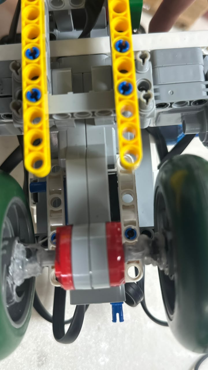
EV3 Large Motor mounted inside the current Cheese v4 chassis.
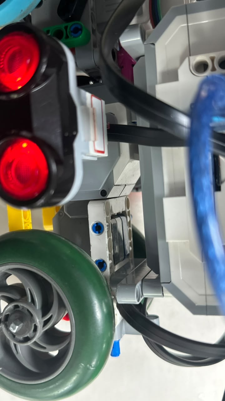
Side view showing how the drive motor is integrated into the lower structure.
### Rear drive wheels
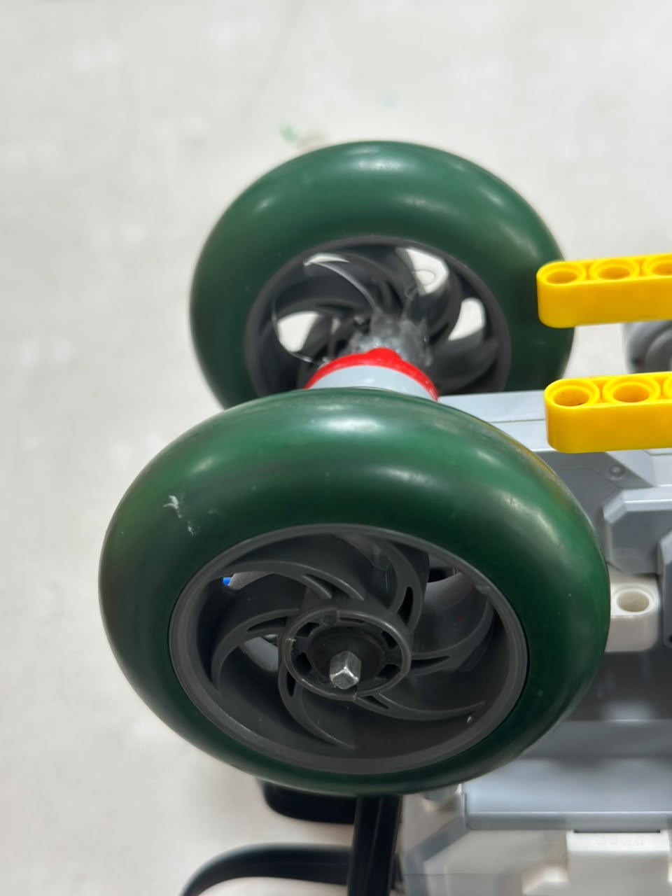
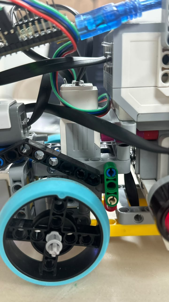
Current EV3 Medium Motor installation inside the v4 steering structure.
--- ## ❀ 1.3.4 Steering Linkage ────୨ৎ────────୨ৎ──── The Medium Motor does not directly rotate the front wheels. Instead, motor movement passes through a mechanical linkage made from LEGO Technic elements. | Step | Mechanical Action | | :--- | :--- | | **1** | Medium Motor rotates. | | **2** | The linkage transfers the movement. | | **3** | Steering arms change position. | | **4** | Front-wheel angles change. | | **5** | Cheese follows the resulting curved path. | The linkage must satisfy two competing requirements:
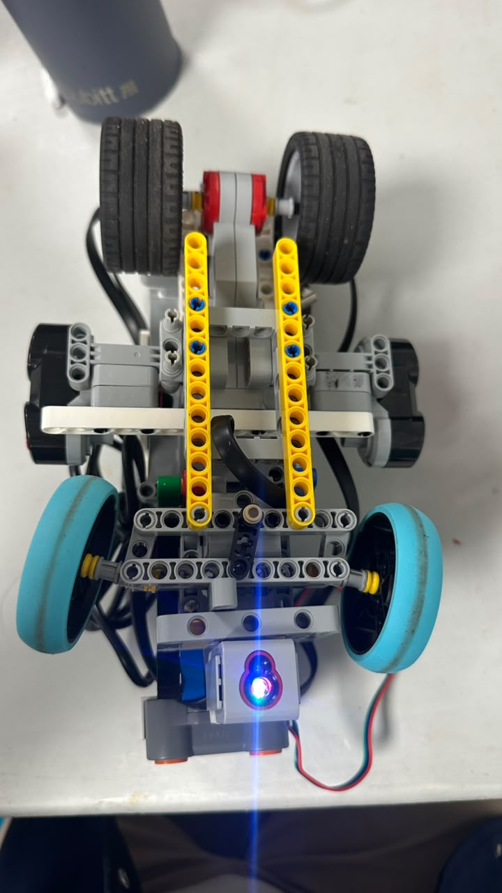
Top view of the current v4 steering assembly showing the front wheels, steering linkage, structural supports, and connection points.
--- ## ❀ 1.3.5 Ackermann Steering Geometry ────୨ৎ────────୨ৎ──── Cheese uses **Ackermann steering geometry**. During a turn, the inner and outer front wheels travel around different circles. The inner wheel follows a smaller radius, while the outer wheel follows a larger radius. Therefore:θ inner > θ outer
The inner wheel must turn more sharply than the outer wheel. ### Mathematical model Let: | Symbol | Meaning | | :---: | :--- | | **R** | Turning radius measured from the turning center | | **T** | Front track width | | **L** | Wheelbase | | **θ inner** | Inner-wheel steering angle | | **θ outer** | Outer-wheel steering angle | The two wheel paths can be represented as:
Inner radius = R − T/2
Outer radius = R + T/2
tan(θ inner) = L / (R − T/2)
tan(θ outer) = L / (R + T/2)
θ inner > θ outer
This geometry reduces the need for the front wheels to slide sideways through a curve. ### Why this matters If both wheels were forced to follow an inappropriate identical steering path, additional tire scrub could occur. | Effect | Consequence | | :--- | :--- | | **Tire scrub** | Additional friction during turns | | **Side loading** | Extra force on steering components | | **Poor repeatability** | Corners may behave differently | | **Energy loss** | Motor effort is wasted through friction | ### Physical v4 implementation The physical steering geometry can be inspected directly in the current front assembly:
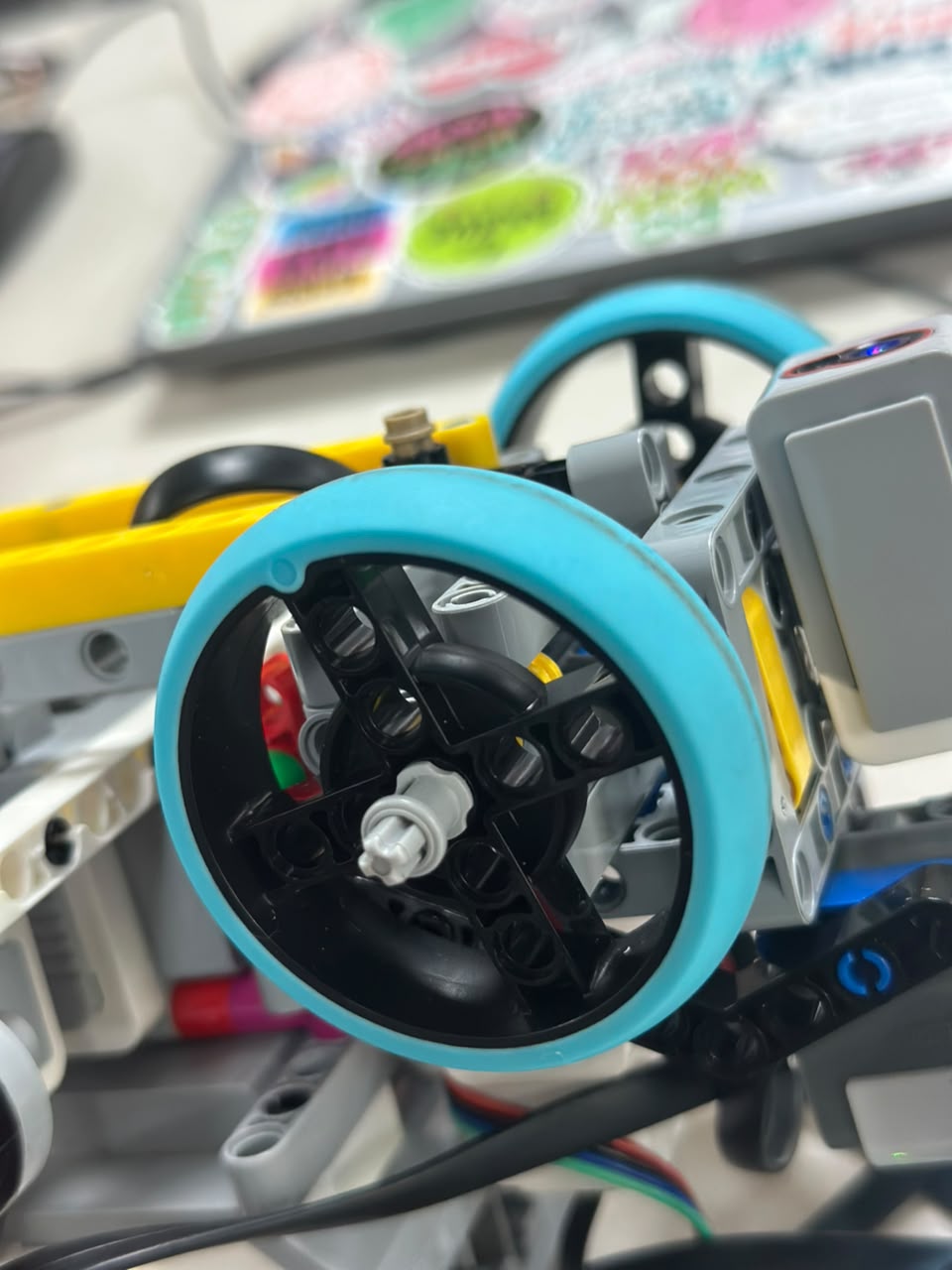
Current v4 front-wheel configuration used by the Ackermann steering system.
--- ## ❀ 1.3.6 Steering Development: Failure → Fix ────୨ৎ────────୨ৎ──── The current steering mechanism was not created in one attempt. Testing across the different versions exposed mechanical problems that changed the design. | Version | Observation | Engineering Response | Lesson | | :--- | :--- | :--- | :--- | | **v1** | Original linkage was too stiff. | Changed the joint configuration. | A steering linkage must pivot freely. | | **v2** | Revised joint moved more freely. | Working geometry was retained. | Lower mechanical resistance improved steering movement. | | **v3** | Aggressive turns stressed the front structure. | Steering support was reinforced. | A good linkage still requires a rigid foundation. | | **v4** | Excess structure added unnecessary mass and complexity. | Surrounding structure was simplified. | Reinforcement should exist only where mechanically necessary. | ### Early steering redesign
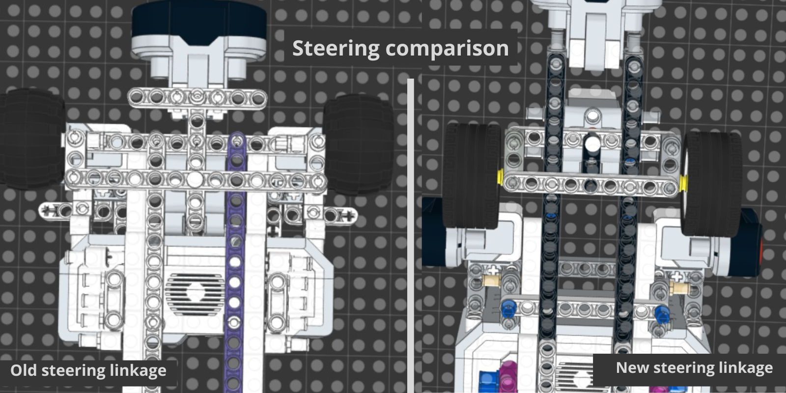
Early steering comparison documenting the change from the original linkage to the improved mechanism.
### v3 reinforced structure
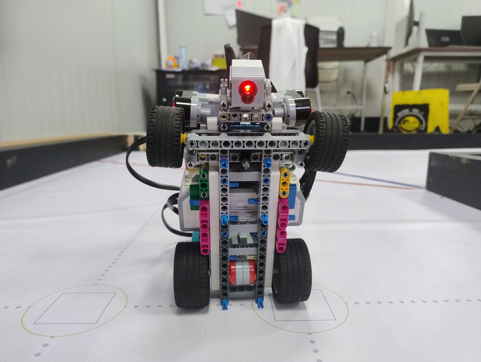
Bottom view of the previous v3 steering and chassis arrangement.
### v4 simplified structure
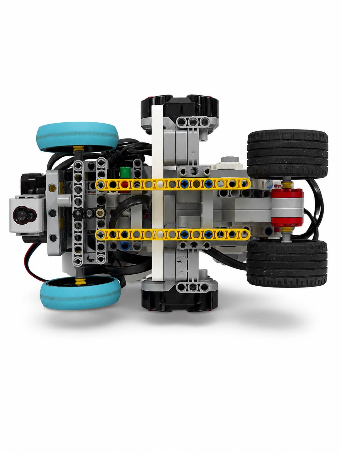
Current v4 lower structure after mechanical simplification.
--- ## ❀ 1.3.7 Current v3 → v4 Steering Comparison ────୨ৎ────────୨ৎ──── The latest mechanical comparison is documented in the dedicated v3-to-v4 steering analysis.



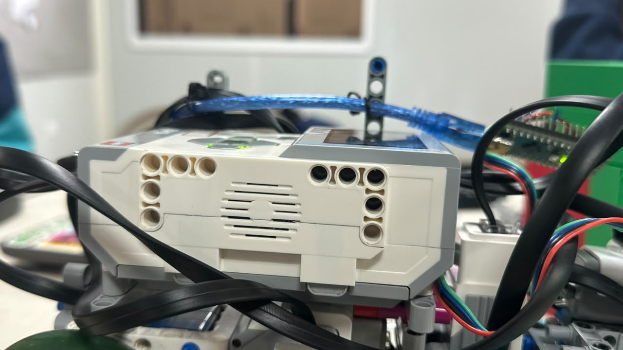
The EV3 Brick is positioned low in the current v4 structure.
### Removed structure
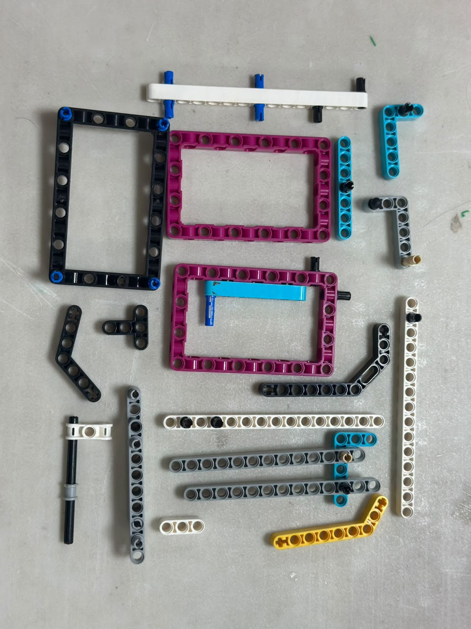
Structural elements removed during the transition from v3 to v4, documenting the physical simplification of the robot.
The main engineering trade-off was therefore: > **Reduce unnecessary mass without sacrificing steering rigidity.** --- ## ❀ 1.3.9 Steering Stability During Curves ────୨ৎ────────୨ৎ──── Mechanical steering and software control directly affect each other. A mechanically correct steering mechanism can still produce a poor corner if the robot approaches too quickly. Likewise, good software cannot compensate indefinitely for a loose or restricted mechanical linkage. | Failure | Possible Cause | Response | | :--- | :--- | :--- | | **Late turn** | Robot reaches the corner before sufficient steering angle develops. | Adjust speed and curve timing. | | **Turn too sharp** | Steering correction is excessive. | Reduce or smooth steering command. | | **Linkage stress** | Sudden steering movement loads the structure. | Maintain strong supports and smoother control. | | **Poor curve exit** | Steering does not return appropriately after the corner. | Tune return-to-center behavior. | | **Wall contact** | Speed, steering angle and timing are not synchronized. | Tune the complete motion system together. | This became one of the main lessons from testing:Driving speed must match steering response.
--- ## ❀ 1.3.10 Current Physical Evidence ────୨ৎ────────୨ৎ──── The following evidence is already available in the repository. | Evidence | Repository File | Engineering Purpose | | :--- | :--- | :--- | | **Large Motor mounting** | `../../v-photos/v4/large_drive_motor_mount_v4.jpg` | Documents current propulsion motor installation. | | **Large Motor side view** | `../../v-photos/v4/large_drive_motor_side_v4.jpg` | Shows drivetrain integration into the chassis. | | **Rear drive wheels** | `../../v-photos/v4/rear_drive_wheels_v4.jpg` | Documents the driven rear-wheel arrangement. | | **Medium steering motor** | `../../v-photos/v4/medium_motor_internal_v4.jpg` | Shows the current steering actuator. | | **Ackermann assembly** | `../../v-photos/v4/ackermann_steering_top_v4.jpg` | Shows the physical steering linkage and front geometry. | | **Front wheel system** | `../../v-photos/v4/front_spike_wheels_v4.jpg` | Documents the current v4 front wheels. | | **v4 bottom view** | `../../v-photos/v4/bottom_v4.jpg` | Shows steering, drivetrain and lower chassis arrangement. | | **v4 front view** | `../../v-photos/v4/front_v4.jpg` | Shows the current front structure. | | **v4 side view** | `../../v-photos/v4/left_v4.jpeg` | Shows the lower overall v4 structure. | | **Lower EV3 placement** | `../../v-photos/v4/ev3_low_position_v4.jpg` | Documents the current EV3 Brick position. | | **Removed structure** | `../../v-photos/v4/removed_structural_parts_from_v3_to_v4.jpg` | Provides evidence of v4 structural simplification. | | **v3 bottom structure** | `../../v-photos/v3/bottom_v3.jpg` | Provides comparison evidence from the previous version. | | **Early steering evolution** | `../../v-photos/v2/Steering_comparison.png` | Documents an earlier steering redesign. | | **v3 → v4 comparison** | `../../schemes/steering_comparison_v3_to_v4.pdf` | Documents the latest steering-system evolution. | --- ## ✦ 1.3 Engineering Conclusions ─── ⋆⋅☆⋅⋆ ─── The development of Cheese showed that steering performance cannot be attributed to one component. The **EV3 Large Motor** provides propulsion, the **EV3 Medium Motor** controls the steering linkage, and the **Ackermann geometry** determines how the front wheels follow a curve. Their performance also depends on chassis rigidity, robot mass, motor mounting, linkage freedom, speed and software tuning. The progression from v1 through v4 followed a repeated engineering process:Failure → Observation → Mechanical Change → Testing → Further Refinement
The current v4 design keeps the important steering geometry and structural supports while removing unnecessary mass and upper structure. This produced a **666 g** robot with a cleaner and more accessible steering and drivetrain arrangement.
Key lesson:
The lightest steering system is not automatically the best one.
The goal is to remove unnecessary structure while preserving the rigidity,
alignment and freedom of movement required for repeatable steering.
✦ ─── ⋆⋅☆⋅⋆ ─── (❁´◡`❁) ─── ⋆⋅☆⋅⋆ ─── ✦
