# WRO_2026_Future_Engineers
# Hello! We are **Team Fast 5**.
# WRO Future Engineers - Robotics Project Documentation
## Our Team

Fast 5 is a team of two students from Kid Engineer Organization, also known as Thay Phong STEM, competing in the WRO Future Engineers category. This repository documents our full engineering process for design, components, testing, and code for our self-driving car.
## Team Members
| Photo | Member | Role |
|---|---|---|
|  | **Luu Duc Trung** | Lead mechanical builder - brings prior WRO experience (WRO 2018, 2021, 2023, 2024, 2025) and designed/assembled the robot |
|  | **Truong Dinh Bach** | Responsible for documenting the team's development process and photography |
## Table of Contents
- [1. Overview](#1-overview)
- [1.1 About the Project](#11-about-the-project)
- [1.2 Robot Images](#12-robot-images)
- [1.3 Performance Video](#13-performance-video)
- [2. Mobility Management](#2-mobility-management)
- [2.1 Drive System](#21-drive-system)
- [2.2 Steering](#22-steering)
- [2.3 Chassis Design](#23-chassis-design)
- [3. Power and Sense Management](#3-power-and-sense-management)
- [3.1 Power Source](#31-power-source)
- [3.2 Sensors and Camera](#32-sensors-and-camera)
- [3.3 Processing Units](#33-processing-units)
- [3.4 Port / Wiring Map](#34-port--wiring-map)
- [3.5 Power Consumption](#35-power-consumption)
- [4. Obstacle Management](#4-obstacle-management)
- [4.1 Open Challenge](#41-open-challenge)
- [4.2 Obstacle Challenge](#42-obstacle-challenge)
- [4.3 Parallel Parking](#43-parallel-parking)
- [5. Source Code](#5-source-code)
- [5.1 Code Overview](#51-code-overview)
- [5.2 Code Structure](#52-code-structure)
- [5.3 Upload / Run Instructions](#53-upload--run-instructions)
- [6. List of Components](#6-list-of-components)
- [7. 3D Model Files](#7-3d-model-files)
- [8. Building Instructions](#8-building-instructions)
---
## 1. Overview
### 1.1 About the Project
This project is our self-driving car for the WRO Future Engineers category: an autonomous vehicle that completes the **Open Challenge** (three laps of an unknown, randomised track without touching a wall) and the **Obstacle Challenge** (three laps while reading and reacting to red/green traffic signs, followed by parallel parking).
This is the first year our team has competed in this category, so a large part of this project has been building up new engineering and programming experience from scratch - much of it inherited from Trung's two prior seasons in the Robo Sports
Our robot is built on a **custom LEGO Technic + 3D-printed (PLA) chassis**, in a **rear-wheel differential-drive, Ackermann front-steer** configuration, controlled by a **LEGO® Education SPIKE™ Prime Hub** and a **Matrix Robotics M-Vision Cam** for onboard image processing. Design priorities, in order, were: a low center of gravity for stability, a lightweight structure to reduce motor strain, and a minimal footprint for maneuverability.
The current build is our **second full revision (v2)** - see §2.3 for what changed from v1 and why.
### 1.2 Robot Images
Front View
 |
Left View
 |
Right View
 |
Back View
 |
Top View
 |
Bottom View
 |
### 1.3 Performance Video
[Open Challenge run](https://youtu.be/gR-lhKKfd4c)
[Obstacle Challenge run]()
Back To Top
---
## 2. Mobility Management
- **Drive system:** rear-wheel differential drive.
- **Steering:** front-wheel Ackermann steering.
### 2.1 Drive System
**Motor: LEGO® Technic™ Large Angular Motor** (drives the rear differential)
 |
Specifications
- Connector: LEGO® Power Functions 2.0 (LPF2)
- Voltage range: 5–9V (SPIKE Hub nominal: 7.2V)
- No-load speed: ~175 RPM (team measurement, vs ~135 RPM for the stock SPIKE-branded Large Angular Motor)
- Feedback: integrated rotation/position sensor
|
**Reason for Selection**
- Higher RPM than the stock SPIKE motor, for faster lap times on the flat competition arena.
- Smaller footprint with more mounting-hole positions on the case, giving flexibility in where it sits on the chassis.
- Built-in rotation sensor gives closed-loop feedback for encoder-based distance/angle control (see `Enc_cal`, `MotorB_degree` in §5).
**Differential Gear**
A LEGO differential sits between the two rear wheels, letting them spin at different speeds through a turn - the inner wheel travels a smaller-radius arc than the outer wheel, so without a differential one wheel would have to scrub/slip. This keeps cornering smooth and reduces wheel wear and drift, particularly during tight turns in the Obstacle Challenge and during parking.
**Wheels: 62.3 mm Technic tires (rear)**
Wide, large-diameter tires were chosen for the rear (driven) wheels to maximize grip and acceleration off the line and out of turns.
**Considerations**
The Large Motor's torque is adequate for the flat competition surface but is a limiting factor for future speed increases - a heavier gear-down or a higher-torque motor is a candidate upgrade if we push for faster lap times.
### 2.2 Steering
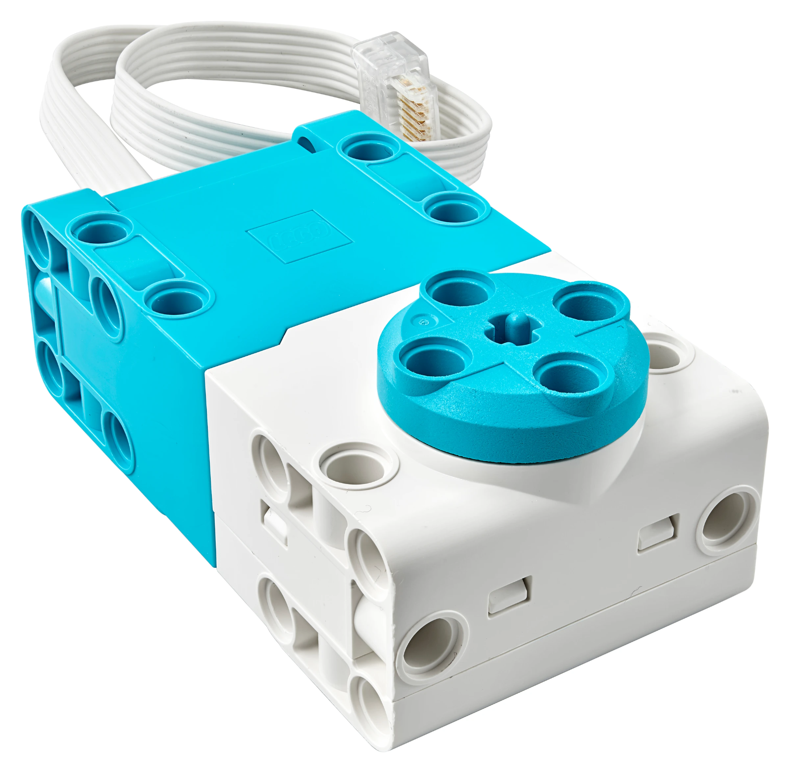
**Motor: LEGO® Technic™ Large Angular Motor + 1:1 gearbox**
 |
Specifications
- Connector: LPF2
- Voltage range: 5–9V
- Stall torque: ~40 N·cm with the 1:1 gearbox (team measurement, vs ~25 N·cm for the stock SPIKE Angular Motor)
- Feedback: integrated rotation/position sensor, used for heading/angle-based turns (`MotorB_Angle`)
|
**Reason for Selection**
- Highest available stall torque among LEGO Powered Up motors, needed to move the Ackermann linkage under load.
- Position feedback lets steering angle be driven and held precisely rather than open-loop.
**Steering geometry: Ackermann steering**
We use Ackermann geometry so the two front wheels turn at different angles in a corner - the inner wheel (tracing the smaller-radius arc) turns more sharply than the outer wheel - letting both wheels roll without slipping. This is the same principle full-scale cars use for efficient, accurate turning, and it matters for us in tight obstacle-avoidance maneuvers and parking, where precision beats raw turning speed.

**Wheels: 49.5 mm SPIKE wheels (front)**
Small diameter for agility and quick direction changes at the steered wheels.
**Considerations**
Even with the 1:1 gearbox, torque at the steering linkage was tighter than expected after the first v2 build - a candidate area to revisit (e.g. a different gear ratio or linkage geometry) if we find the robot under-steering at speed.
### 2.3 Chassis Design
**Design Overview**

The chassis is built from **LEGO Technic**, supplemented with **custom 3D-printed PLA parts** wherever no suitable LEGO piece exists - most notably the Ultrasonic sensor Adapter. LEGO was our starting material because the team (particularly Trung) has multiple prior seasons of hands-on build experience with it; 3D printing filled the remaining gaps and gave us full freedom over part geometry.
**v1 → v2 changes**
| Change | Reason |
|---|---|
| Elevated, forward-mounted camera → lower, front-mounted camera | Removed scaffolding weight/instability while keeping an adequate field of view |
| Longer chassis → shorter chassis | Lower, more centralized mass → better stability in sharp turns, less drift |
| SPIKE wheel (rear) → 62.3 mm LEGO wheel (rear) | More rear-wheel friction on the driving surface |
Back To Top
---
## 3. Power and Sense Management
### 3.1 Power Source
**Battery: SPIKE Prime rechargeable Li-ion Hub Battery**
Specifications
- Type: rechargeable lithium-ion, charged in-hub via micro-USB
- Capacity: ~2,000–2,100 mAh (per LEGO Education spare-part listings)
- Working range used in our firmware: 6,900–8,300 mV (see
Battery() in §5), consistent with a 2-cell Li-ion pack
|
The battery powers the SPIKE Prime Hub directly; the Hub in turn supplies all motors and sensors over their LPF2 leads, and the M-Vision Cam over its dedicated 5V cable - no separate step-up/step-down conversion is needed anywhere in the system, since the camera's 5V input matches the Hub's output.
Our firmware reads `hub.battery.voltage()`, clamps it to the 6,900–8,300 mV working range, and converts it to a 0–100% estimate so we can catch a low-charge robot before a run.
**Considerations**
Because everything runs off one Hub battery with no separate motor supply, our power architecture is much simpler than a Raspberry Pi-class system (no MOSFET power-switching, no DC-DC boost converter, no separate motor driver IC) - the tradeoff is that we're bound to whatever voltage/current the Hub itself can deliver.
### 3.2 Sensors and Camera
**Camera: Matrix Robotics M-Vision Cam (Type-C cable pack)**
Specifications
- Processor: STM32H7, 480 MHz
- Interface: UART over LPF2 to the SPIKE Prime Hub
- Operating voltage: 5V (matches Hub output directly)
- Color space: LAB (in addition to RGB/HSV)
|
**Reason for Selection**
- Has its own onboard processor, so the Hub doesn't have to run image-processing algorithms itself - this saves battery and keeps the Hub's CPU free for motor/sensor control.
- Supports **LAB color space**, which separates brightness (L) from color (A/B). Since the A/B axes stay comparatively stable when the arena's lighting shifts brighter or darker, LAB gives more consistent line/color detection than RGB or HSV under variable lighting.
**Tasks:** line following and wall-fill detection (Open Challenge); red/green traffic-sign blob detection, magenta parking-wall detection, and lap-boundary color detection (Obstacle Challenge).
**Distance sensing: 2× LEGO® Technic™ Distance Sensor (ultrasonic)**
Specifications (manufacturer)
- Sensing technology: ultrasonic
- Range: 50-2,000 mm (fast-sensing mode: 50–300 mm)
- Accuracy: ±1 cm
- Extras: 4-segment programmable LED "eyes"; detachable LPF2 breakout on the rear
|
**Tasks:** one sensor on each side reads distance to the left/right walls. At the start of a run, this tells the robot whether the course is Clockwise or Counterclockwise (by checking which side has a wall); during a run, it feeds `Ultra_err()`/`Ultra_steer()` to hold a consistent stand-off from the wall and correct heading error.
**Ground sensing: LEGO® Technic™ Color Sensor**
Specifications (manufacturer)
- Detects 8 discrete colors, plus RGB/HSV values
- Measures reflected light intensity (for line-following) and ambient light
- High sample rate for consistent, repeatable readings
|
**Tasks:** reads ground color for lap-boundary/start-line detection, feeding `Color_read()` and `Color_line_count()` for lap counting.
### 3.3 Processing Units
**Controller: LEGO® Education SPIKE™ Prime Hub**
| | Mindstorms EV3 | SPIKE Prime |
|---|---|---|
| CPU Clock Speed | 300 MHz | 100 MHz |
| Weight (incl. battery) | 385 g | ~200 g |
| Volume | 0.388 L | 0.158 L |
**Reason for Selection**
We chose SPIKE Prime over EV3 even though its CPU clock speed is lower, because it's roughly half the weight and less than half the volume of the EV3 Hub - both of which matter more for our low-CG, lightweight design goals than raw clock speed, given that the M-Vision Cam (not the Hub) does the heavy image-processing work.
### 3.4 Port / Wiring Map
Everything connects to the Hub over standard LEGO LPF2 cables - no custom wiring harness or PCB is needed. Current assignments (from `FE_Functions.py`):
| Hub Port | Device | Role |
|---|---|---|
| A | Matrix M-Vision Cam | Line / wall / traffic-sign detection |
| B | Technic Large Motor | Drive (rear differential) |
| C | Technic XL Motor | Steering (Ackermann linkage) |
| D | Distance Sensor (right) | Right-wall distance |
| E | Color Sensor | Ground color / lap detection |
| F | Distance Sensor (left) | Left-wall distance |
### 3.5 Power Consumption
All components are powered from the SPIKE Prime Hub's own 7.3 V Li-Ion battery.
| Component | Voltage | Current (typical) | Current (peak) | Power (typical) |
|---|---|---|---|---|
| SPIKE Prime Hub | 7.2 V | 1.0 A | 1.5 A | 7.2 W |
| M-Vision Camera | 5 V (Type-C) | 0.15 A | 0.3 A | 0.75 W |
| Ultrasonic ×2 | 5 V (from hub) | 0.04 A | 0.06 A | 0.2 W |
| Drive motors ×2 | 7.2 V | 1.0 A | 2.0 A | 7.2 W |
| **Total** | | **2.19 A** | **3.86 A** | **15.35 W** |
Back To Top
---
## 4. Obstacle Management
The competition has two runs:
- **Open Challenge:** three laps around a randomly-sized field, in a randomly-chosen direction, without touching a wall.
- **Obstacle Challenge:** three laps while reading traffic signs - pass a red sign on its right, a green sign on its left - then parallel-park in a marked bay.
We split our strategy into the same three phases:
### 4.1 Open Challenge
Two boxes are drawn on the left and right of the camera frame. Pixels within a tuned RGB threshold count as "black," and the robot centers itself on the track by comparing the black-fill ratio of the two boxes, correcting with **PID** steering. A box at the center of the frame watches for the orange/blue start-line color; whichever color it sees first tells the robot whether the course is Clockwise or Counterclockwise. Two small boxes at the bottom of the frame catch the case where the robot gets close enough to a wall that the main boxes lose the line, switching to a "priority correction" mode driven by those bottom boxes instead - this stops the robot from hugging the wall or losing track when the front sensors go unreliable. A tunable default wall-hugging offset (e.g. +30°) keeps the robot tracking tightly and minimizes lap time.
Click here to show Open Challenge code excerpt
```python
Add = 200 if Cam_val[0]>10 and Cam_val[1]>10 else 0
while GetColor() == 0:
steering(0)
Drive.reset_angle(0)
while abs(Drive.angle()) < Add:
steering(0)
if GetColor() == 1:
ColorCondition = 1
Plus = -30
else:
ColorCondition = -1
Plus = 40
for i in range(11):
while GetColor() != ColorCondition:
SteerCamOpen(ColorCondition, Plus)
while GetColor() == ColorCondition:
SteerCamOpen(ColorCondition, Plus)
Drive.reset_angle(0)
while abs(Drive.angle()) < 2000:
SteerCamOpen(ColorCondition, Plus)
```
### 4.2 Obstacle Challenge
Sign avoidance runs as a four-state routine on the Hub, layered on the same wall-following and corner-counting loop as the Open Challenge (`Ultra_err()` for wall stand-off, `Steer_err()` for the corner-count-based turn target). Each cycle the camera reports an x/y position and color for the nearest sign, plus the percentage of black track surface in view; the state machine below decides what to do with that reading.
**Scanning:** with no sign in view, the robot drives the same baseline heading as the Open Challenge, just with a wider 90° corner cut (`Steer_err(90)` vs. `Steer_err(75)`) to leave more room to spot and clear signs. The moment a sign appears, it switches to tracking it.
**Approaching:** the robot steers straight at the sign using its camera x-offset from center, holding the last good heading if the camera briefly loses it. Once the sign fills enough of the frame (`y >= 100`), the robot commits to the avoidance swing.
**Avoiding:** the target heading swings about 60° off the approach line, the side set by the sign's color, matching the red-right / green-left rule, clamped to within 85° of the current baseline heading so it can't over-rotate. It holds that swing until the track surface reappears (`black` fill above 60%), or gives up and returns to Scanning if 250 encoder-degrees pass without finding it.
**Settling:** for a short window after clearing a sign, until `black` fill passes 70% or 200 more encoder-degrees pass, the robot ignores new sign readings, so it doesn't immediately re-trigger on the one it just passed.
Drive power is also capped lower than the Open Challenge (30–50% vs. 70–100%), and steering runs through `SteerObs()`, a gentler, ±40°-clamped controller — instead of `Steer()`, trading speed for the precision needed to line up on each sign.
*(This section previously described a per-frame PD/blob-width design; it's been rewritten to match the state-machine approach now in `main_obstacle()`.)*
### 4.3 Parallel Parking
After completing 3 laps, the robot aligns to the wall using the same wall-following method as above, then drives until the magenta parking-lot color crosses a specific X-coordinate in the camera frame. From that trigger point, a **pre-programmed, encoder-based maneuver sequence** completes the park - deliberately not a fully vision-guided park, since the travel distance involved is short enough that encoder error stays within an acceptable margin, and it avoids depending on vision precision we haven't yet fully validated for this sub-task.
Back To Top
---
## 5. Source Code
### 5.1 Code Overview
- **Language/runtime:** Pybricks (MicroPython) on the SPIKE Prime Hub.
- **Vision:** OpenMV IDE on the M-Vision Cam, using the `LPF2` import so it can talk to the Hub.
- **Custom libraries:** `MXLineT_Lib` (camera/line-tracker interface).
### 5.2 Code Structure
```txt
repo-root
└─ src
├─ Camera
│ ├─ LPF2.py # External library (depends on libcamera)
│ ├─ main.py
├─ Controller
│ ├─ FE_Functions.py
│ ├─ FE_Portview.py
│ ├─ FE_RUN.py # Executable for both open and obstacle challenges
```
**Key function groups in `FE_Functions.py`:**
| Group | Functions | Role |
|---|---|---|
| Utility | `NumberLimit_Clamp()`, `Enc_cal()`, `dist_cal()` | Clamp a value to a safe range; convert cm → motor degrees and back |
| Power | `Battery()` | Reads Hub voltage, clamps 6,900–8,300 mV, returns battery % |
| Color / laps | `Color_read()`, `Color_line_count()` | Classify raw RGB as a line color; count line crossings for laps |
| Wall following | `Ultra_err()` | Compute a steering correction from the two ultrasonic distance sensors |
| Corner targeting | `Steer_err()` | Turn the line-crossing count into a target turn angle (90° every two crossings, plus a tunable per-corner cut) |
| Heading reference | `Theta()`, `Compass()`, `ReTheta()` | Gyro (IMU)-based heading: signed heading, raw 0–360° compass, and signed error to a target heading |
| Drive/steer profiles | `MotorB_On/Stop/Time/Degs/degree/smooth/3step/dist/...`, `MotorB_Angle` | Inherited motor-profile helpers (accel/decel smoothing, 3-stage speed profiles, gyro turn-to-angle), built around a separate `motorB`/`motorC` pair rather than the `move`/`steer` objects the run loops below actually drive — not called by either challenge's main loop in `FE_RUN.py` |
> **Fixed:** the old `Ultra_steer()` syntax gap (`90*Line_count // 2 Line_count % 2 * 45 ...`, missing an operator between `//2` and `Line_count`) is resolved in the current code. The function is now `Steer_err(corner)`, reading `90*(Line_count // 2) + (Line_count % 2) * corner` ,correctly parenthesized, with `corner` passed in per call (`75` for the Open Challenge, `90` for the Obstacle Challenge) instead of a hard-coded `45`.
**Key functions in `FE_RUN.py`:**
| Function | Role |
|---|---|
| `Steer(angle)` | Steering controller (proportional + accumulated error) used in the Open Challenge |
| `SteerObs(angle)` | Gentler, ±40°-clamped steering controller used in the Obstacle Challenge (see 4.2) |
| `portview()` | Bench-test loop — prints battery, encoder, gyro, distance-sensor, color, and camera readings every 500 ms |
| `main_open()` | Open Challenge entry point |
| `main_obstacle()` | Obstacle Challenge entry point (see 4.2) |
### 5.3 Upload / Run Instructions
1. Install the [Pybricks firmware](https://code.pybricks.com) onto the SPIKE Prime Hub (one-time step, via the Pybricks web IDE over USB or Bluetooth).
2. Connect to the Hub from the Pybricks IDE (or VS Code with the Pybricks extension) and open `FE_Functions.py` plus the relevant challenge script.
3. Flash/run the program on the Hub.
4. Separately, open the corresponding vision script in **OpenMV IDE**, connect to the M-Vision Cam over its Type-C cable, and run/save it to the camera so it starts automatically on power-up.
5. Power on the robot - Hub and camera boot together once battery power is applied.
Back To Top
---
## 6. List of Components
| Component | Quantity | Source / Reference |
|---|---|---|
| LEGO® Education SPIKE™ Prime Hub | 1 | LEGO Education |
| SPIKE Prime rechargeable Hub battery | 1 | [LEGO Education 45610](https://education.lego.com/en-us/products/lego-technic-large-hub-battery/45610/) |
| Technic™ Powered Up Large Motor (drive + steering) | 2 | [LEGO 88013](https://education.lego.com/en-us/products/lego-technic-large-angular-motor/45602/) |
| LEGO differential gear | 1 | LEGO Technic |
| 62.3 mm Technic tires (rear) | 2 | LEGO Technic |
| 49.5 mm SPIKE wheels (front) | 2 | LEGO SPIKE Prime |
| Matrix Robotics M-Vision Cam + Type-C cable pack | 1 | Matrix Robotics |
| LEGO® Technic™ Distance Sensor (ultrasonic) | 2 | [LEGO Education 45604](https://education.lego.com/en-us/products/lego-technic-distance-sensor/45604/) |
| LEGO® Technic™ Color Sensor | 1 | [LEGO Education 45605](https://education.lego.com/en-us/products/lego-technic-color-sensor/45605/) |
| Custom 3D-printed PLA parts (mounts, brackets) | Various | 3D-printed in-house |
| LEGO Technic structural elements | Various | LEGO Technic |
**Printers Used:**
- [Bambu Lab P1S](https://asia.store.bambulab.com/products/p1s?p=W3sicHJvcGVydHlLZXkiOiJWYXJpYW50IiwicHJvcGVydHlWYWx1ZSI6IlAxUyBDb21ibyJ9LHsicHJvcGVydHlLZXkiOiJTaGlwIHRvIiwicHJvcGVydHlWYWx1ZSI6IiJ9LHsicHJvcGVydHlLZXkiOiJPcHRpb24iLCJwcm9wZXJ0eVZhbHVlIjoiQ29tYm8gd2l0aCBIdWIoU2hpcCBTZXBhcmF0ZWx5KSJ9XQ%3D%3D)
Back To Top
---
## 7. 3D Model Files (SLDPRT)
We used SLDPRT to design the 3D models to finish the robot.
- [**Ultrasonic sensor adapter**](Ultra_adapter.SLDPRT)
- [**Cam Holder**](cam_holder.SLDPRT)
Back To Top
---
## 8. Building Instructions
All the code used in the robot can be found [here](src)
**Step 0 - Print the 3D parts:** print all custom PLA parts listed in §7.
**Step 1 - Assemble the steering system:** front wheel linkages → Ackermann/reverse-Ackermann linkage → mount to chassis → attach XL steering motor → secure front wheels.Using File of the Chassis can be found [here](models/Chassis_Design)
**Step 2 - Assemble the drivetrain:** rear wheel axles → differential → Large drive motor → secure to chassis → attach rear wheels.
**Step 3 - Mount electronics:** SPIKE Prime Hub placement → M-Vision Cam mounting/aiming → Distance Sensors (left/right) → Color Sensor → route and connect all LPF2 cables per the port map in §3.4.
**Step 4 - Upload the software:** follow §5.3 to flash the Hub and camera, then power on and test.
Back To Top
---
*Sources: team FAST 5, robot configuration notes, `FE_Functions.py`, and official LEGO Education / LEGO.com technical specification pages linked above.*