# The Mech Minds · WRO Future Engineers 2026
 Our autonomous vehicle for the WRO Future Engineers category. This page documents the **current Raspberry Pi 5 + Build HAT version**.
## System overview
The Raspberry Pi 5 reads a forward-facing USB camera and decides when to follow a wall, correct course, turn a corner, or bypass a coloured pillar. A Raspberry Pi Build HAT operates the LEGO steering and drive motors. A Force Sensor on port C starts the run and stops it when pressed again. **Track direction is detected from the camera, not from a colour sensor.**
```mermaid
flowchart TD
A["USB camera"] --> B["Raspberry Pi 5"]
B --> C["vision.py: detect"]
C --> D["main.py: decide"]
E["Force Sensor C: start / stop"] --> D
D --> F["vehicle.py: Build HAT commands"]
F --> G["Steering motor A / drive motor B"]
```
**Figure 1. Current hardware and software data flow.** Port assignments for A and B are based on the current robot setup; the supplied `main.py` directly identifies only the Force Sensor on C.
| Part | Role |
| --- | --- |
| Raspberry Pi 5 | Runs Python, OpenCV, vision processing, and navigation decisions |
| USB camera | Supplies 640 × 480 frames, requested at 30 fps |
| Build HAT | Controls the LEGO motors and reads the Force Sensor |
| Steering motor, port A | Turns the front wheels through the steering linkage |
| Drive motor, port B | Drives the rear wheels |
| Force Sensor, port C | Start and second-press stop |
### Current vehicle photographs
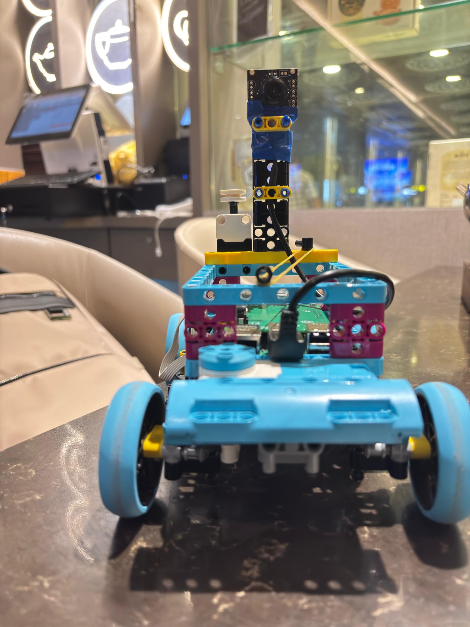
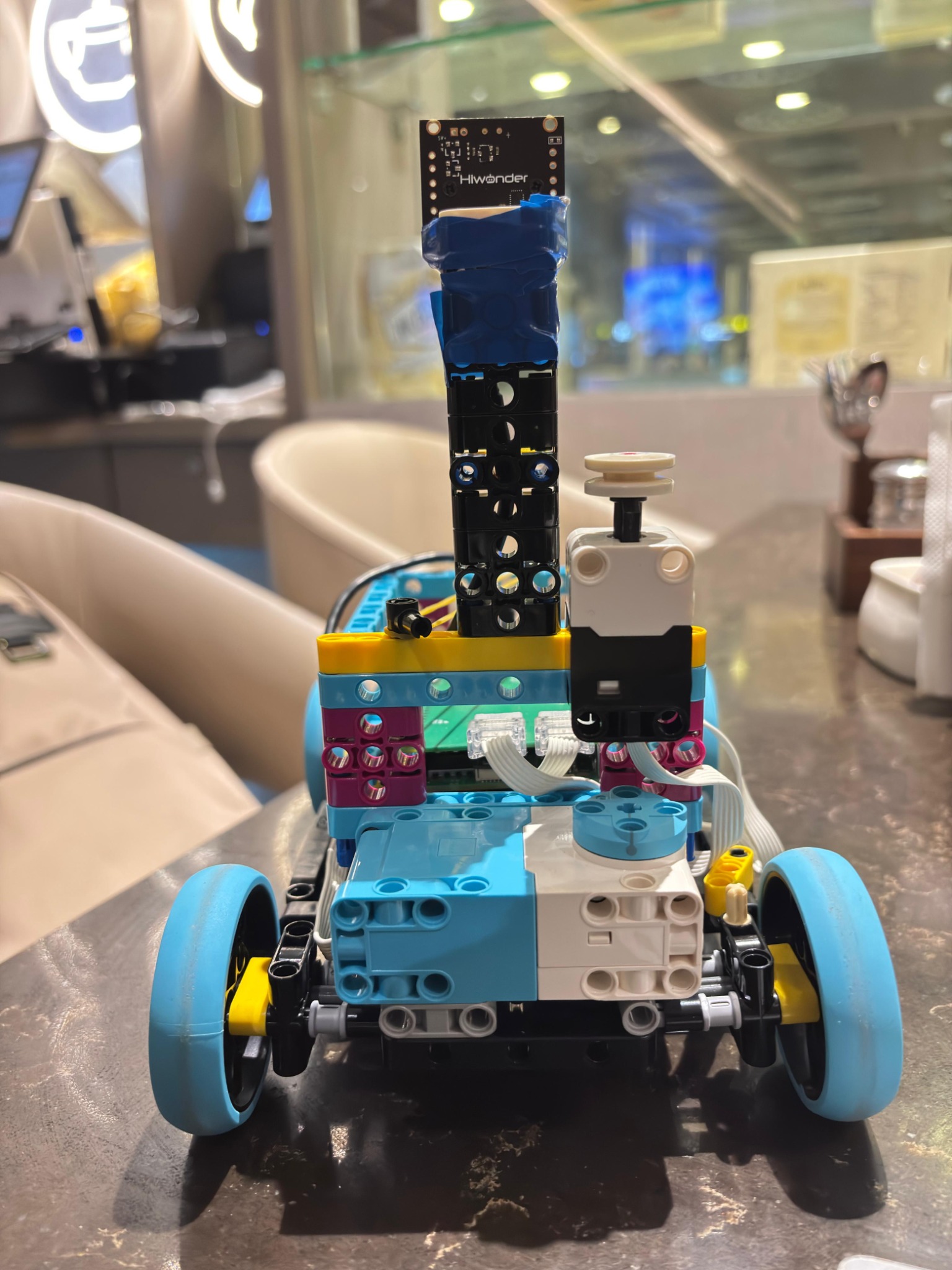
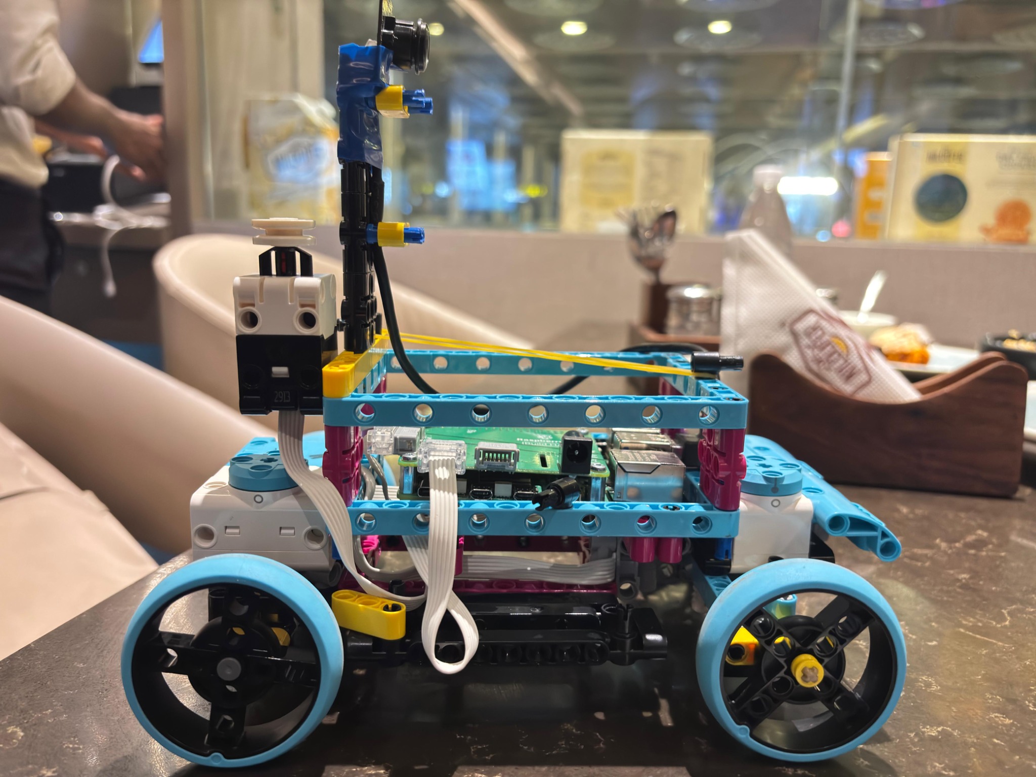
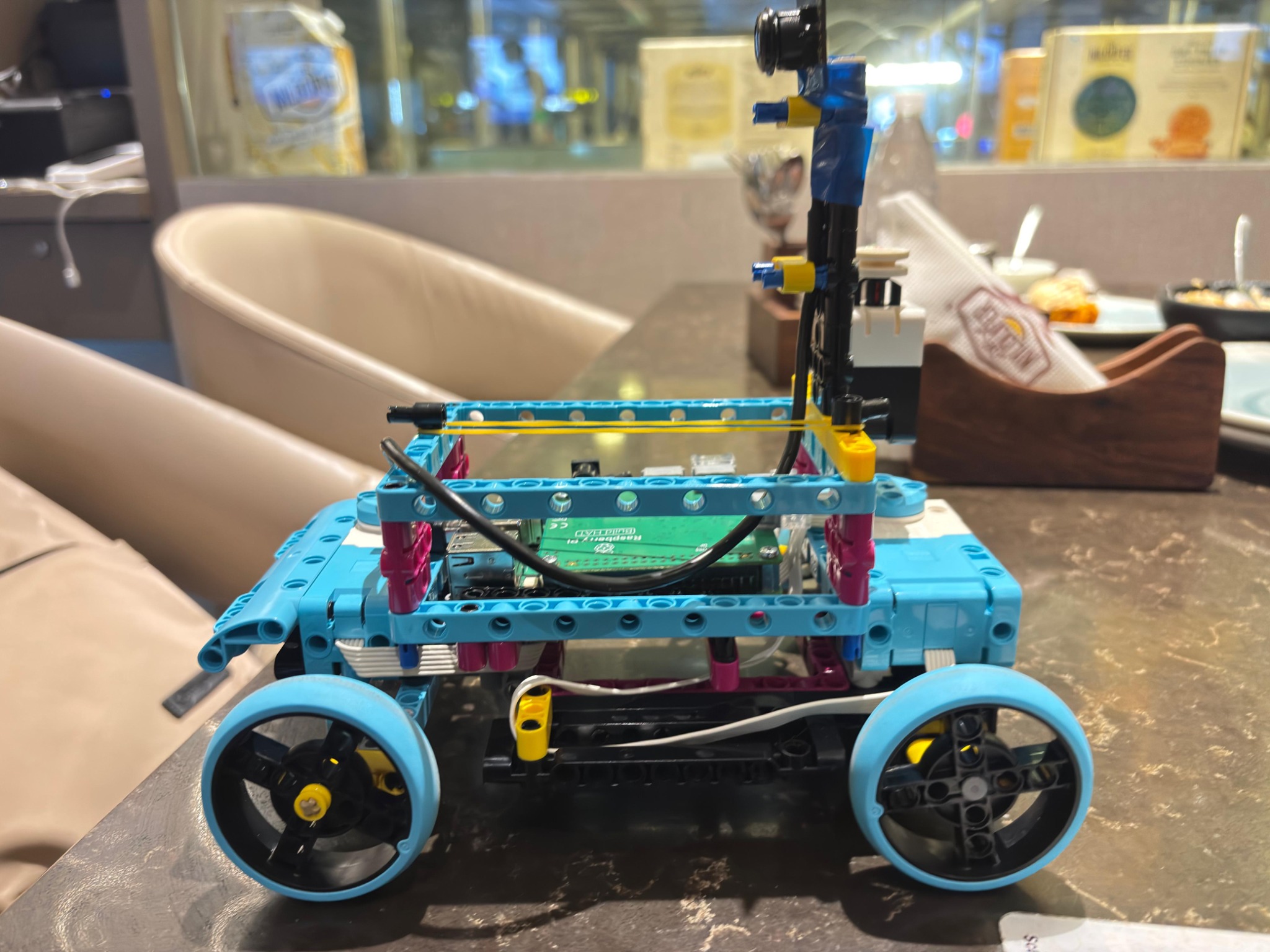
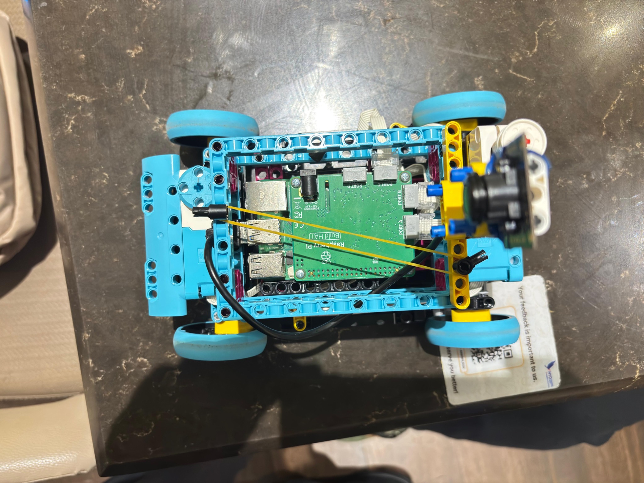
These five views show the Raspberry Pi 5 and Build HAT vehicle, with its high-mounted Hiwonder USB camera, Force Sensor, LEGO motors, frame, and wiring. The [hardware overview](others/current-hardware.svg) summarizes their connections. The front is the end facing the camera lens. An underside view of this revision has not been supplied.
| Front, camera facing forward | Rear, camera board visible |
| --- | --- |
|
 |
 |
| Left side | Right side | Top |
| --- | --- | --- |
|
 |
 |
 |
## Software structure
| File | Responsibility | Current repository status |
| --- | --- | --- |
| [`src/vision.py`](src/vision.py) | Camera acquisition, coloured line and pillar detection, dark wall ratios, direction lock, lap count, debug overlay | Supplied implementation; debug line counter corrected to show the 13-crossing stop target |
| [`src/main.py`](src/main.py) | Wait for start, choose the action each frame, handle corners and stopping | Uploaded exactly as supplied |
| [`src/vehicle.py`](src/vehicle.py) | Build HAT steering, driving, correction, stop, and centring | Added as a configurable starting implementation; calibrate on the robot |
The main loop checks conditions in this order:
1. **Second button press, camera failure, or Q:** leave the run.
2. **Race complete:** command straight for 0.5 seconds and leave the run.
3. **Green pillar:** call `vehicle.left()`.
4. **Red pillar:** call `vehicle.right()`.
5. **Front wall:** turn right if clockwise, or left if counterclockwise, until vision reports `FRONT_CLEAR`.
6. **Otherwise:** use `LEFT_CORRECT`, `RIGHT_CORRECT`, or straight driving from the vision navigation hint.
```mermaid
flowchart TD
A["New vision frame"] --> B{"Race complete?"}
B -->|Yes| C["Straight 0.5 s, stop"]
B -->|No| D{"Pillar?"}
D -->|Green| E["Left"]
D -->|Red| F["Right"]
D -->|None| G{"Front wall?"}
G -->|Yes| H["Turn by locked direction until clear"]
G -->|No| I["Side correction or straight"]
```
**Figure 2. Decision order in `main.py`.** The obstacle response is issued on each frame; this version does not include a timed obstacle lock or a reverse manoeuvre in `main.py`.
### Vehicle calibration
`src/vehicle.py` starts with port A for steering and port B for drive, a motor speed of 20, steering speed 30, centre 0°, full turn ±25°, and correction ±10°. These are **initial values, not measured settings**. Check wheel centring and rotation direction with the drive wheels lifted before a track run. Environment variables `TMM_STEERING_PORT`, `TMM_DRIVE_PORT`, `TMM_CENTER_ANGLE`, `TMM_TURN_ANGLE`, `TMM_CORRECTION_ANGLE`, `TMM_STEERING_SPEED`, `TMM_DRIVE_SPEED`, and `TMM_STEERING_DIRECTION` adjust the setup without editing the file. Set `TMM_STEERING_DIRECTION=-1` if left and right are reversed; use a negative drive speed if forward runs backward. The class sends nonblocking steering positions and keeps the drive motor running until `stop()`.
## Camera regions and detection
The current `vision.py` sets the following pixel coordinates in a 640 × 480 frame. Coordinates are `(x1, y1, x2, y2)`; the bottom of the image has a larger `y` value.
| Purpose | ROI | Processing |
| --- | --- | --- |
| Direction lock | `(20, 150, 620, 440)` | Orange and blue HSV masks; compare line centre `y` positions |
| Lap line | `(40, 220, 600, 440)` | Orange or blue contour, minimum line area 80 px² |
| Pillars | `(50, 210, 590, 455)` | Red/green HSV masks, area and shape validation |
| Left wall | `(20, 260, 150, 455)` | Ratio of dark pixels |
| Front wall | `(145, 205, 495, 350)` | Ratio of dark pixels |
| Right wall | `(490, 260, 620, 455)` | Ratio of dark pixels |
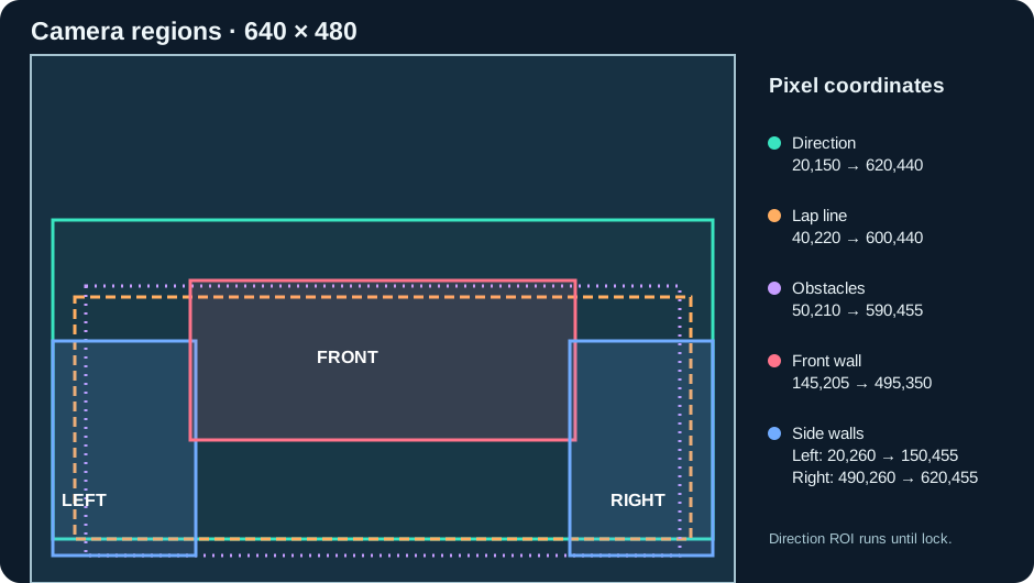
**Figure 3. Exact regions from `vision.py`.** The diagram uses the source coordinates.
### Camera views from track testing
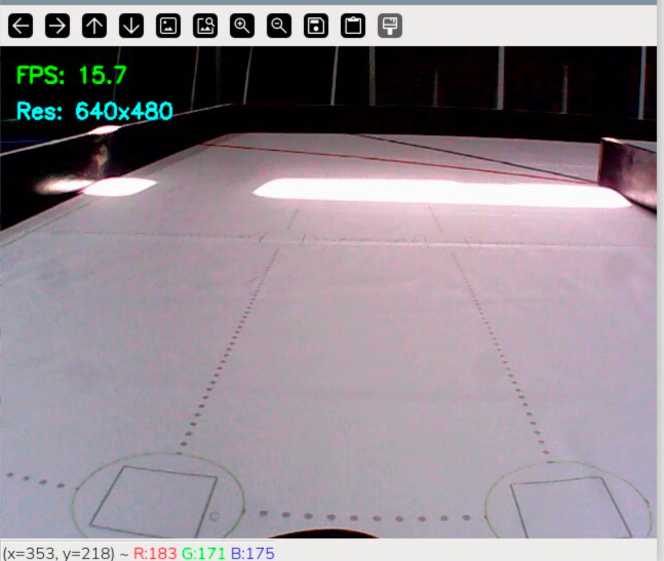
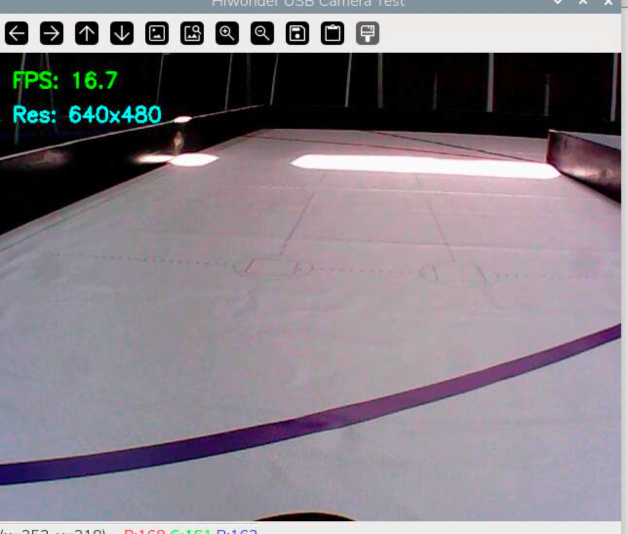
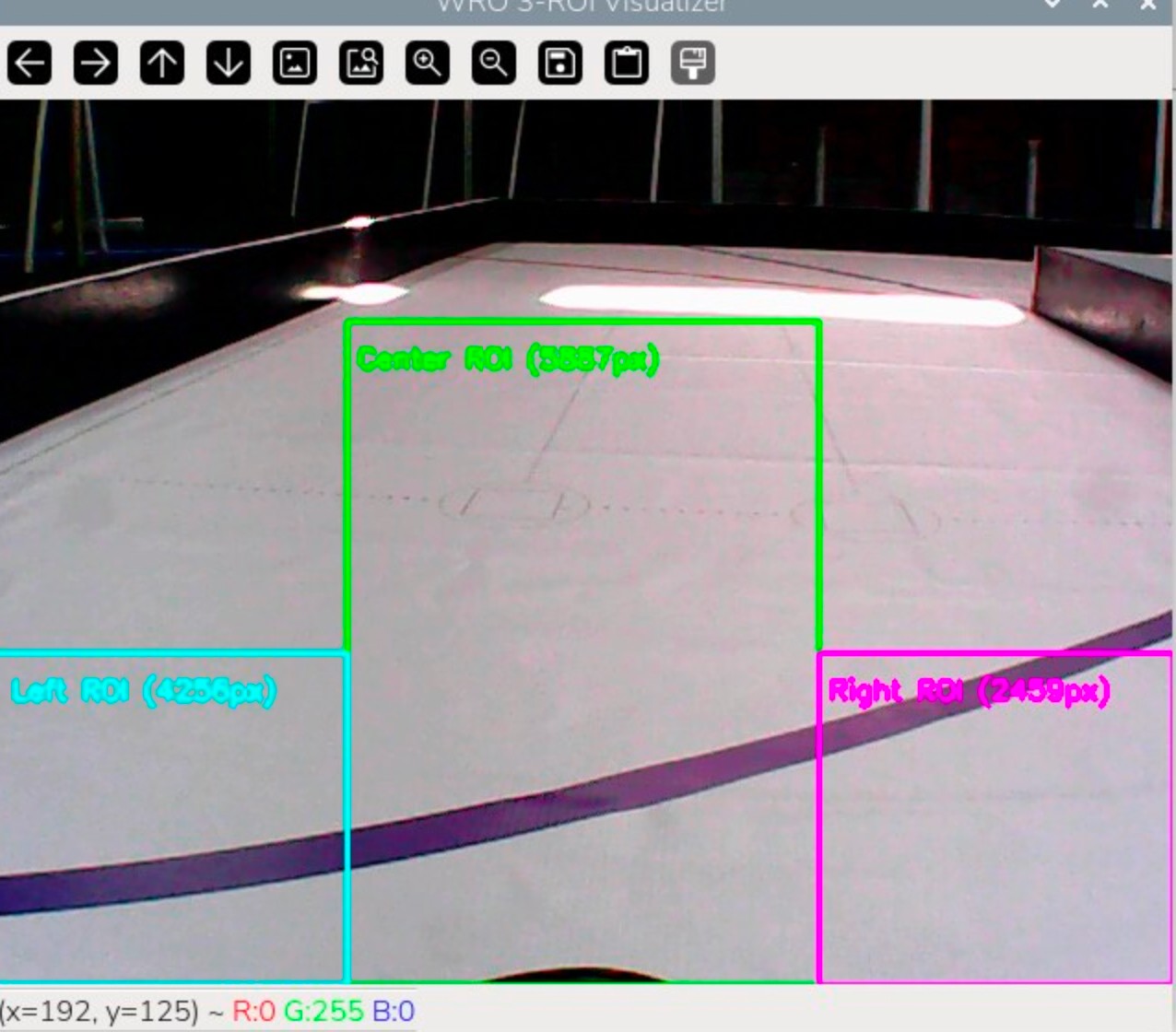
These camera captures document field of view and detection overlays from a **development test program on 21 September 2026**. Its coloured boxes and pixel counters are not the output format of the current `src/vision.py`.
| Unannotated track view | Blue line in view |
| --- | --- |
|
 |
 |
The earlier overlay below shows central and side inspection regions used while tuning camera placement.
 ### Direction detection
Direction starts as `UNKNOWN`. Both orange and blue lines must be present inside the direction ROI. If their vertical centres differ by less than **20 pixels**, the observation is rejected. When orange has the larger `y` coordinate, it is closer to the bottom of the frame and the candidate direction is **CLOCKWISE**. When blue has the larger `y`, the candidate is **COUNTERCLOCKWISE**. The same ordering must be seen for **three consecutive frames** before direction locks. Once locked, the code does not reconsider it.
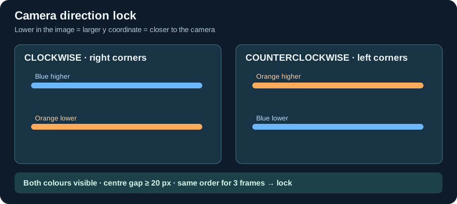
**Figure 4. Direction lock from orange and blue line positions.**
After direction locks, both start lines must disappear from the normal line ROI before lap counting is enabled. This prevents the start markings from being counted immediately.
### Walls and corners
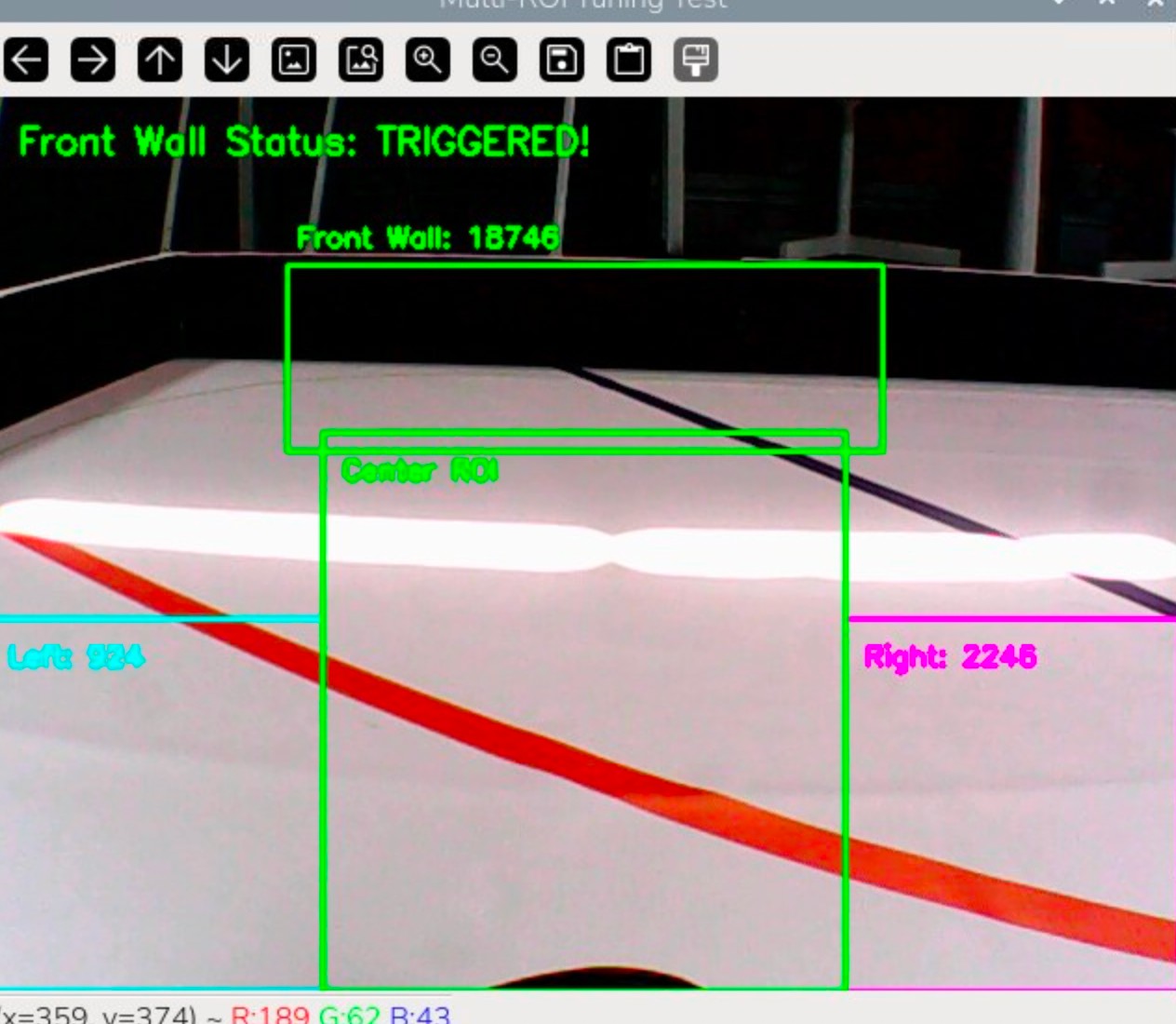
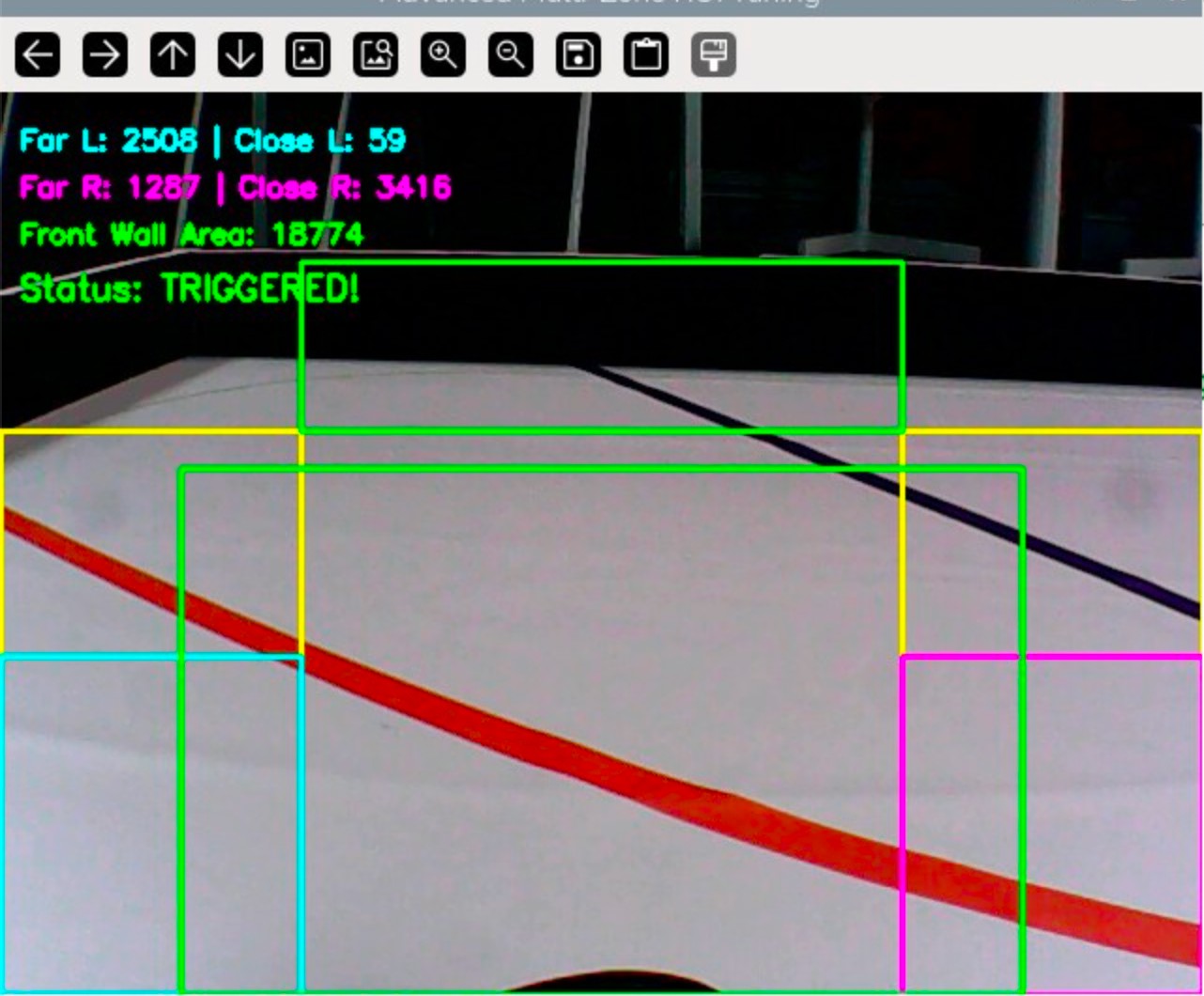
The camera frame is converted to grayscale, blurred, thresholded at **100**, and morphologically opened before dark-pixel ratios are calculated. A front ROI ratio above **0.15** gives `FRONT_WALL`. A side ratio above **0.22** on only one side causes correction away from that side. When both sides are above threshold, the navigation hint is straight.
At `FRONT_WALL`, clockwise travel calls `vehicle.right()` and all other values, including `UNKNOWN`, call `vehicle.left()` repeatedly until a processed frame reports `FRONT_CLEAR`. The inner loop still checks the camera, Q, the button, and race completion. It does **not** have a turn timeout or a side-wall clearance check in the supplied `main.py`.
### Front wall detection during development
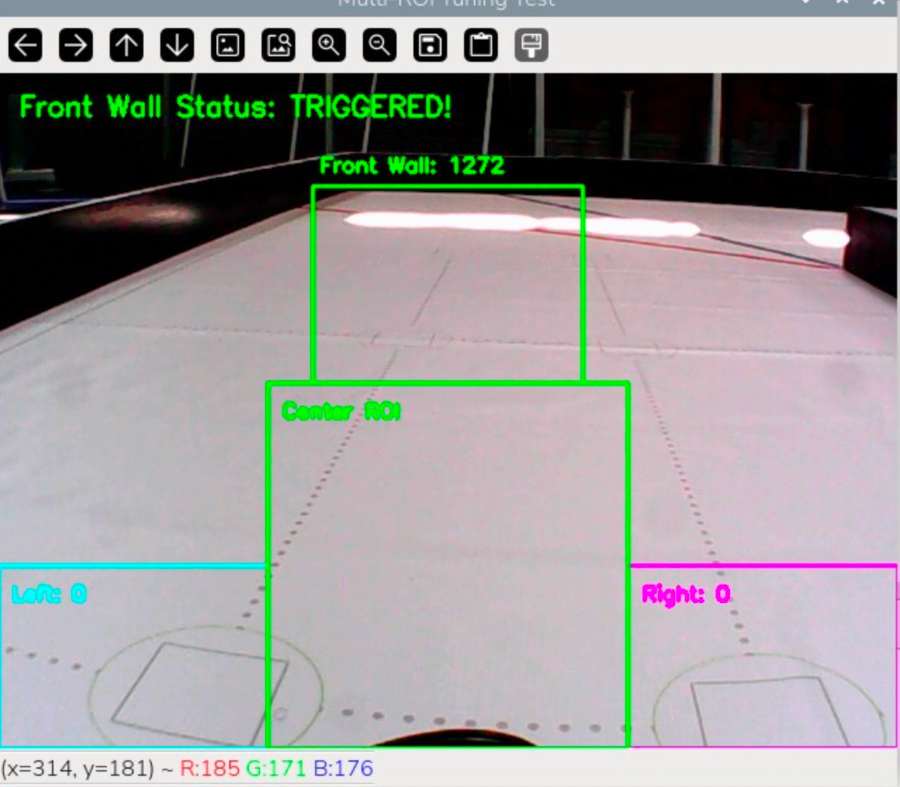
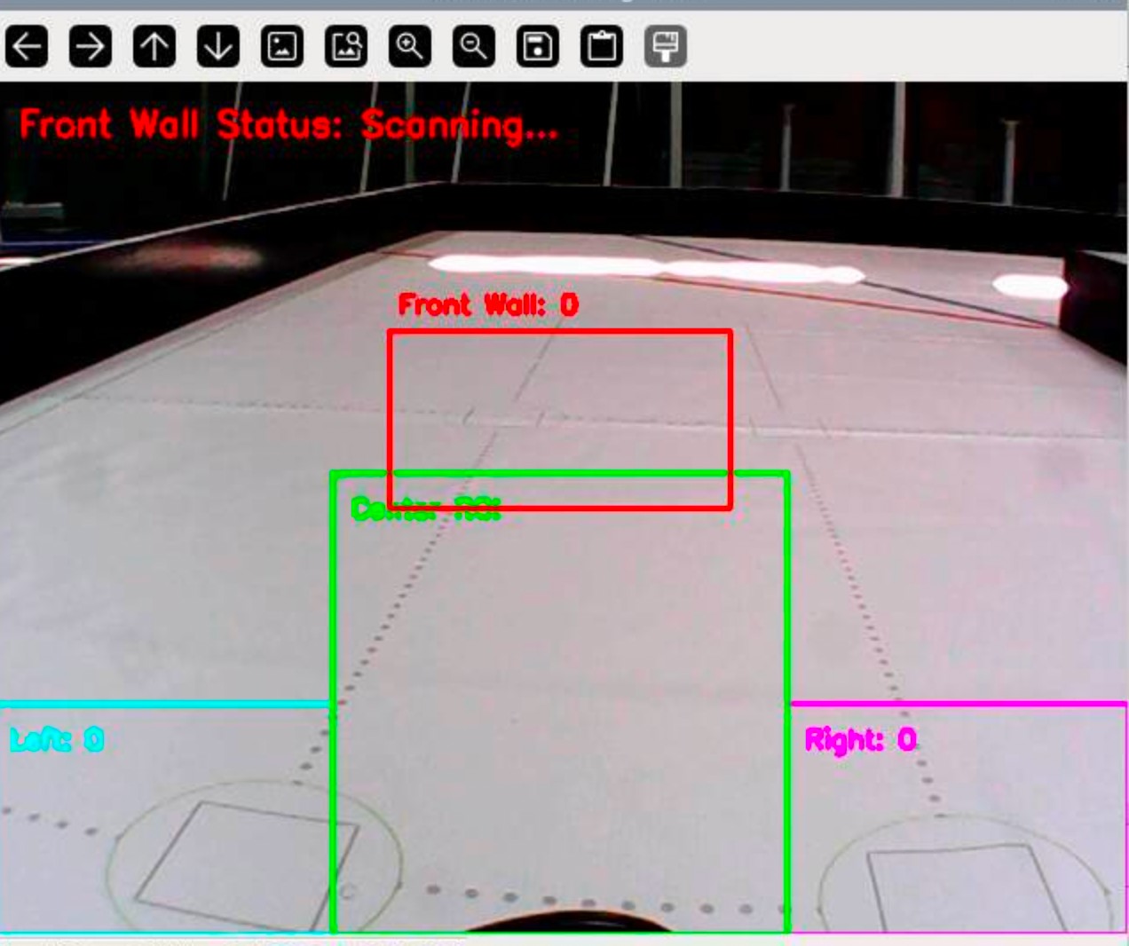
The following screenshots show how an earlier test overlay changed between a detected front wall and a clear front region. They are field-test evidence; their raw pixel counts and drawn rectangles should not be read as the current `vision.py` thresholds.
| Wall detected | Front region clear |
| --- | --- |
|
 |
 |
| Additional front-wall test | Side and front readings |
| --- | --- |
|
 |
 |
### Red and green pillars
The obstacle ROI uses HSV masks, a 3 × 3 closing operation, and contour checks. `MIN_GREEN_OBSTACLE_AREA` is **1000 px²** and `MIN_RED_OBSTACLE_AREA` is **1800 px²**; minimum height is **35 px** and maximum aspect ratio is **1.8**. If both colours pass validation, the larger contour area wins. The main loop steers **left for green** and **right for red**. These are steering commands, not proof of a safe physical clearance. Test both colours near corners and walls.
## Lap counting and stop
Either an orange or a blue line in the normal line ROI can count as one crossing. The counter locks while a line remains visible and rearms only after **five consecutive frames without either line**. Every fourth crossing reports a completed lap: **4 → lap 1, 8 → lap 2, 12 → lap 3**.
The configured `TOTAL_LINE_COUNT` is **13**. Crossing 13 sets `race_complete`; `main.py` then commands straight for 0.5 seconds and stops. The terminal message says “3 LAPS COMPLETED” at this stop reference. **This program does not contain a parking sequence.**
```mermaid
flowchart LR
A["Direction locked"] --> B["Start lines disappear"]
B --> C["Count each rearmed crossing"]
C --> D["4 / 8 / 12: lap reports"]
D --> E["13: race_complete"]
E --> F["Straight 0.5 s, stop"]
```
**Figure 5. Line count sequence.**
## Start, stop, and cleanup
The program initializes `Vision`, `Vehicle`, and `ForceSensor("C")`, stops the vehicle, and displays a live debug view while waiting for the start press. It waits for the button to be released before entering the main loop. During the run, a second press, Q, or camera failure exits. The `finally` block stops the vehicle, centres steering, closes the camera, and destroys OpenCV windows.
**Current code checks before a full-speed run:**
- If a front wall appears while direction is `UNKNOWN`, the current conditional selects `vehicle.left()` because it treats every non-clockwise value as counterclockwise. Ensure direction locks before the first corner or add an explicit safe response.
- A corner turn can continue indefinitely if `FRONT_CLEAR` never appears. Add a bounded timeout or recovery before relying on this at speed.
- The waiting-for-start and button-release loops are outside `try/finally`. Pressing Q before the start raises `SystemExit` without executing the main cleanup block.
- The obstacle branch has no held bypass state or explicit wall-clearance check. Observe how the robot behaves when a pillar briefly leaves the camera view.
- The 0.5-second straight movement after crossing 13 needs track testing so the vehicle stops at the intended position.
## Testing evidence to add
| Test | Evidence |
| --- | --- |
| Direction in both start layouts | Debug overlay showing orange/blue centres, frame confirmation and locked direction |
| Straight and both corners | Continuous video and front/side wall ratios |
| Red and green avoidance | Continuous video, pillar contour and minimum clearance from wall and pillar |
| Pillar near a corner | Both colours tested with corner visible |
| Lap count | Continuous three-lap video with 4, 8, 12 and 13 crossing log |
| Emergency exits | Second button press, Q and camera-disconnect behaviour |
## Prototype evolution
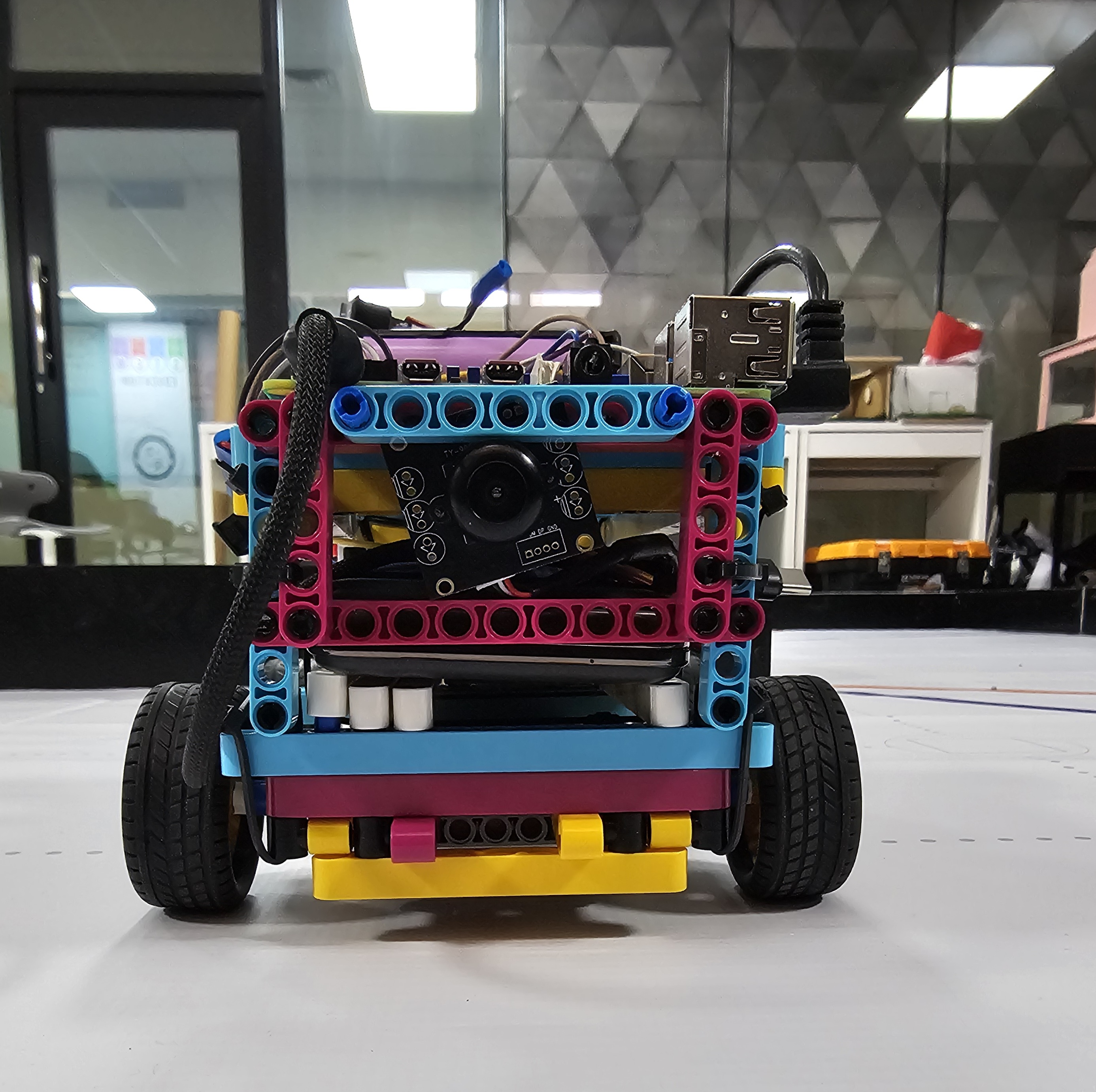
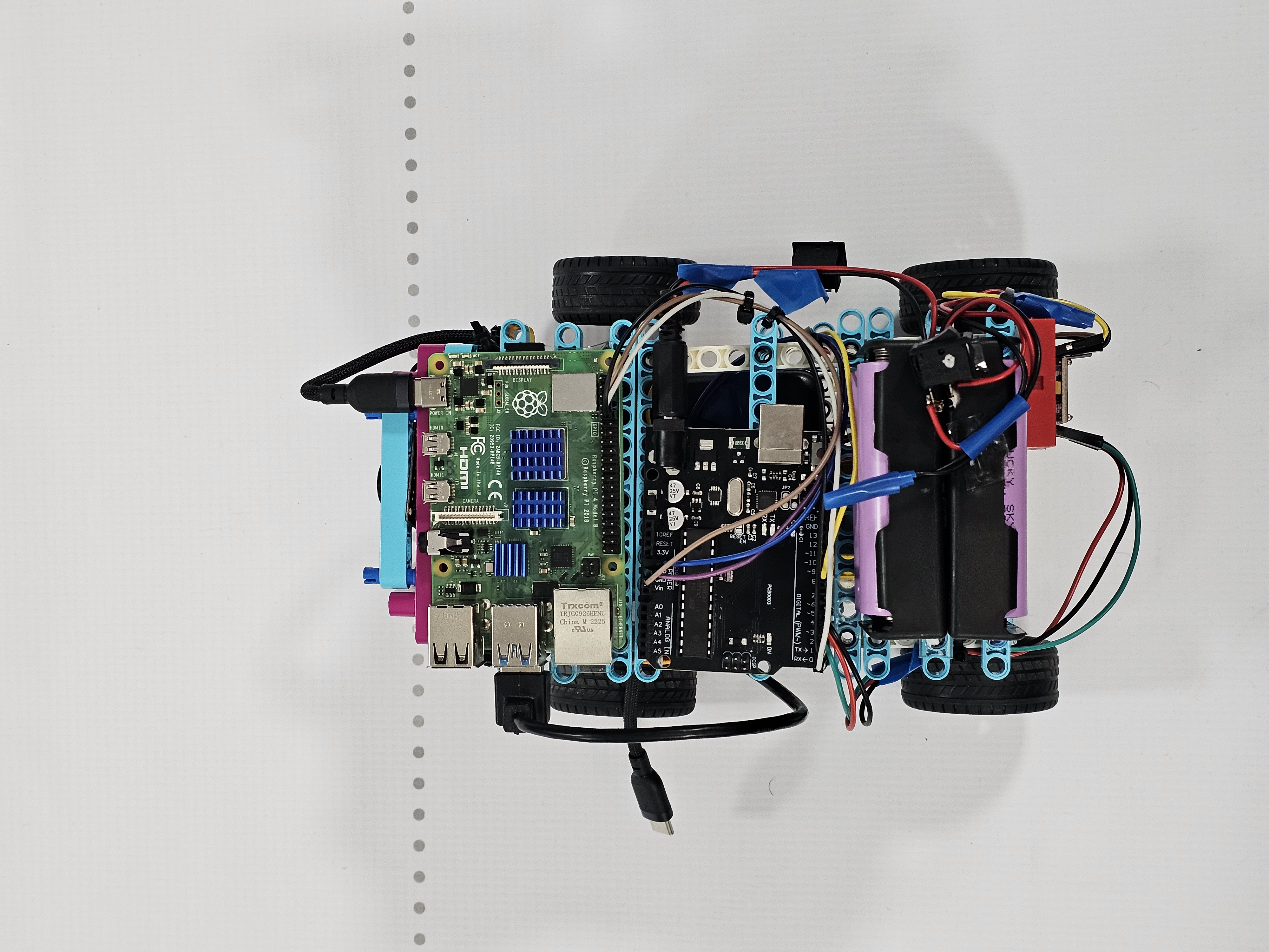
Our robot changed as we tested the camera view, turning behaviour, drivetrain, and power arrangement. The earlier [Pi 4B + Arduino photographs](archive/pi4-arduino/v-photos/) and [hardware illustrations](archive/pi4-arduino/others/) document that iteration. Its main navigation program is still available as [`src/autonomous_main.py`](src/autonomous_main.py). The old `arduino/` source folder has been removed, so the repository does not contain a complete runnable copy of that controller.
| Earlier prototype: front | Earlier prototype: top |
| --- | --- |
|
 |
 |
### Earlier Pi 4B and Arduino approach
The Raspberry Pi 4B captured a 640 × 480 USB camera frame and processed the lower half of the image. OpenCV HSV masks found red and green pillars and the blue floor line. A grayscale threshold of **120**, followed by morphological opening, found dark wall contours. When both side walls were visible, the code estimated the track centre from their inner edges and applied proportional steering. With only one wall visible, it steered away from that wall. If neither wall was visible, it retained the last left or right decision for **0.4 seconds** before returning to centre.
Green pillars commanded left steering; red pillars commanded right. The earlier corner rule always commanded a **right** turn when a front wall was detected. Blue-line crossings were counted on a new visible-line edge, with a **1.5-second cooldown**. After **12 crossings**, the code entered a timed parking sequence: drive forward, reverse straight, reverse with left steering, reverse with right steering, then stop. Steering values of **1750 / 1880 / 2150 µs** (left / centre / right) and a motor command were sent as `servo,motor\n` over **9600-baud UART** to the Arduino. These values belong to the earlier servo controller, not to the Build HAT motors.
### Why we revised it
| What we found while developing | Change in the current revision | Practical effect or remaining gap |
| --- | --- | --- |
| Direct servo control from the Pi had produced jitter and intermittent holding during earlier tests. | The Pi 4B revision handed servo and motor actuation to Arduino. The current Pi 5 revision instead uses LEGO motors through the Build HAT. | `src/vehicle.py` now commands Build HAT motors directly. Its steering centre, limits, and speed are starting settings that still require physical calibration. |
| Earlier power and weight layouts affected reliable movement and turning. The team revised the battery arrangement and rear drive during prototyping. | The current chassis uses a Pi 5, Build HAT, LEGO motors, and a high-mounted Hiwonder USB camera, as shown in the [current vehicle photos](#current-vehicle-photographs). | The repository does not yet specify a verified current power schematic or measured balance and traction results. Do not use the archived Pi 4B battery diagram to wire this vehicle. |
| The old front-wall rule selected a right turn and therefore assumed a clockwise run. | `vision.py` compares orange and blue line positions, confirms the ordering for three frames, and locks **CLOCKWISE** or **COUNTERCLOCKWISE**. `main.py` uses that direction for a corner turn. | The direction lock enables both layouts, but an `UNKNOWN` direction at the first wall still needs a tested response. |
| The old line counter used blue only and a timed cooldown; its final action was timed reverse parking. | The current code detects orange and blue lines, rearms after five clear frames, reports laps at crossings **4, 8, and 12**, and stops after crossing **13**. | The current program has **no reverse parking routine**. The old parking behaviour has not been carried over or validated on the LEGO chassis. |
| A short turn memory helped the earlier code when the walls briefly disappeared. | The current navigation uses fixed left, front, and right image regions with dark-pixel ratios and explicit `FRONT_WALL` / `FRONT_CLEAR` states. | The current `main.py` does **not** implement the old 0.4-second fallback, a timed pillar bypass, or a corner-turn timeout. Those remain candidates for track testing. |
The archived images and older scripts explain how the design developed; they are not setup instructions for the current Pi 5 vehicle. The `models/` folder contained no runtime model and was removed. Its older steering photograph is in [`archive/pi4-arduino/models/`](archive/pi4-arduino/models/).
To reproduce the current build accurately, add an underside photograph, verify the power and motor connections, and record tested motor calibration values. `src/vehicle.py` defaults to steering port A and drive port B; `main.py` reads the Force Sensor on port C.
## References
- [WRO 2026 season resources](https://wro-association.org/competition/2026-season/)
- [Raspberry Pi Build HAT documentation](https://www.raspberrypi.com/documentation/accessories/build-hat.html)
- [OpenCV documentation](https://docs.opencv.org/)