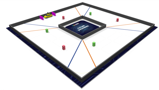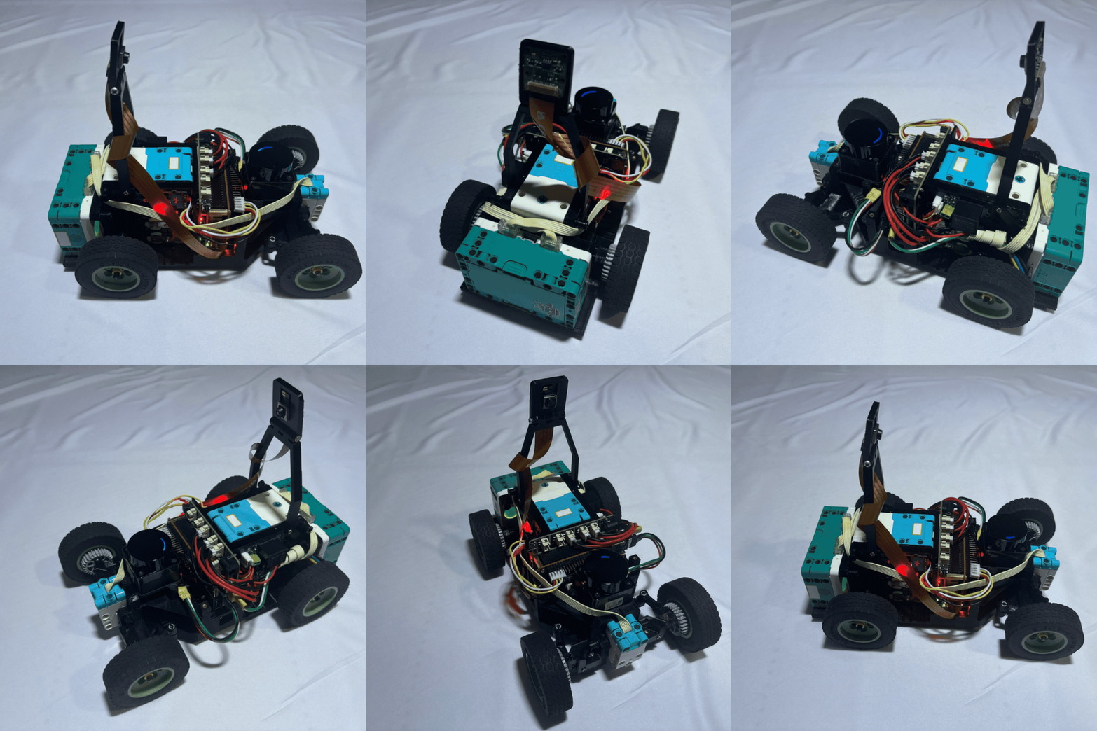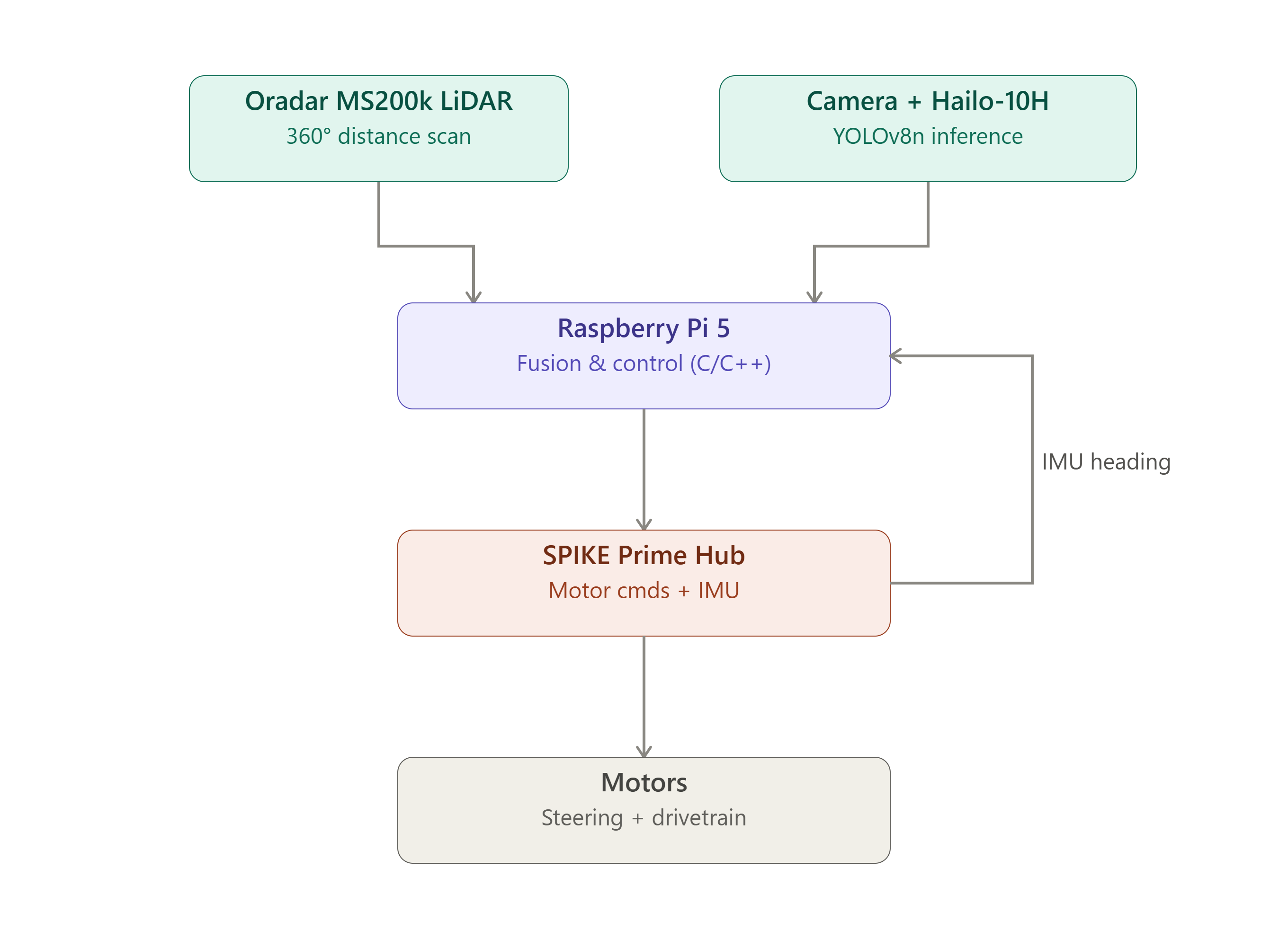
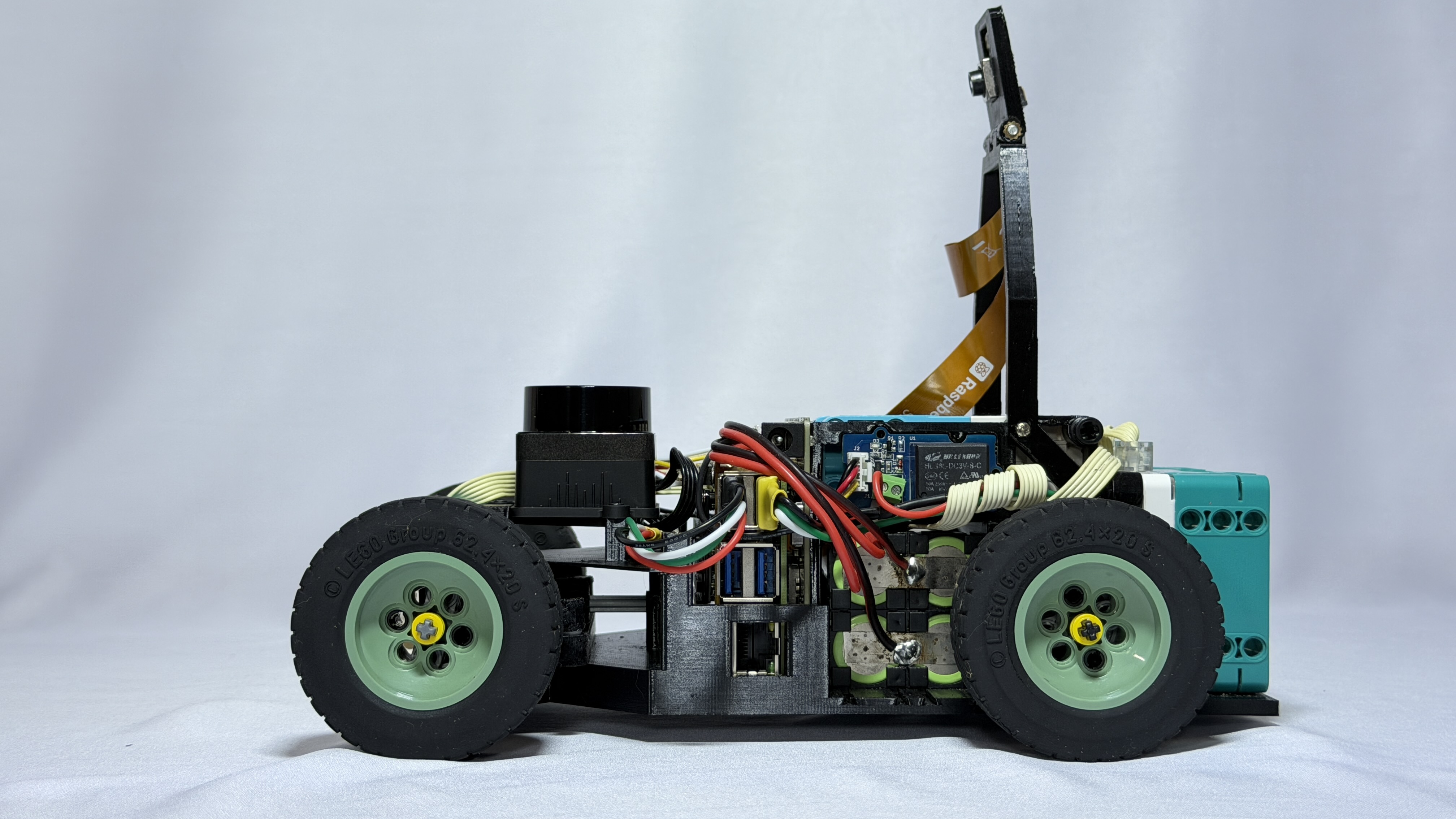
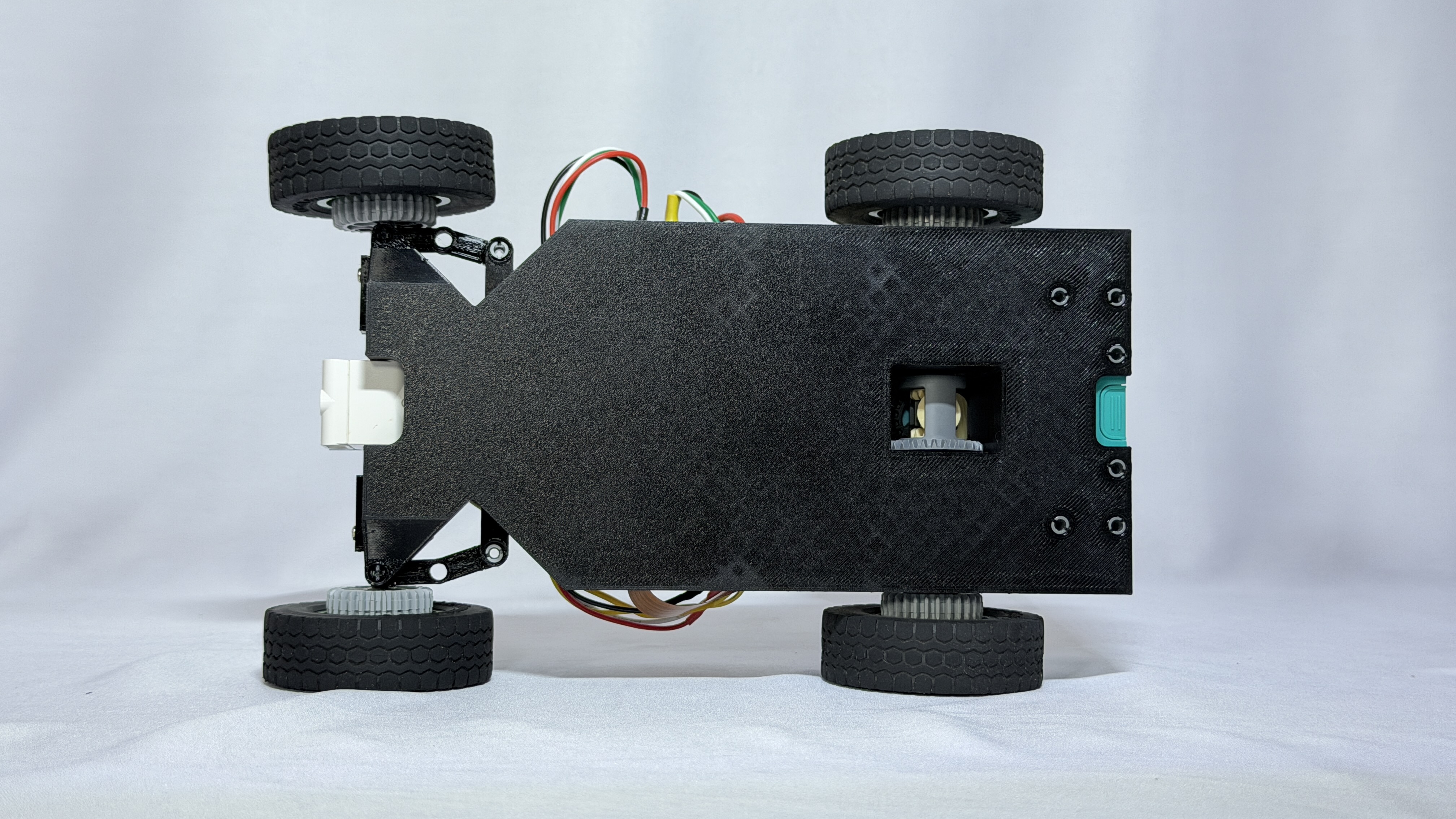
# CSS - WRO Future Engineers 2026 This repository contains the engineering documentation for **CSS**'s autonomous vehicle for the **WRO Future Engineers**, 2026 season. Our team is based in Querétaro, México. --- ## Table of Contents 1. [Our Team](#our-team) 2. [Challenge Overview](#challenge-overview) 3. [Our Robot](#our-robot) - [3.1 Mobility Management](#mobility-management) - [3.2 Power & Sense Management](#power-sense-management) - [3.3 Obstacle Management & Control Strategy](#obstacle-management) 4. [Engineering Process & Design Iterations](#engineering-process) 5. [Construction Guide](#construction-guide) 6. [Bill of Materials (BOM)](#bom) 7. [Repository Structure](#repository-structure) 8. [Setup & Execution Instructions](#setup-instructions) 9. [Driving Videos](#driving-videos) 10. [Resources & References](#resources) 11. [License](#license) --- ## 1. Our Team
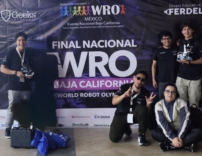
***Disclaimer:*** *This image has been edited to remove former team members who are no longer part of the project, in order to protect their privacy. Editing was done using Microsoft Photos' generative erase feature.* ### Team Members #### Christian Gael Centeno Velez **Age:** 17\ **Role:** Captain. Software, electronics and mechanical design\ >I am currently in my senior year of high school at the Colegio de Estudios Científicos y Tecnológicos del Estado de Querétaro (CECyTEQ), specializing as a Mechatronics Technician. I have a strong background in competitive robotics, having participated in previous editions of the World Robot Olympiad (WRO). In 2024, I competed in the RoboMission category, and in 2025, I secured third place at the national level in the Future Engineers category. Through my years of experience competing in the WRO, I have developed solid skills in robot programming, design, and electronics. #### Sebastián Esquivel Mondragón **Age:** 18\ **Role:** Documentation, electronics and mechanical design\ > Currently pursuing a Bachelor of Science in Mechatronics Engineering at Monterrey Institute of Technology and Higher Education (ITESM), on an academic talent scholarship. My background in robotics began in middle school with the MekLab Robotics team (UAQ), where I competed in WRO RoboMission, placing 3rd nationally in 2022 (Junior) and 2nd nationally in 2023 (Senior), qualifying for the international final in Panama. In 2025, our now independent and disaffiliated team moved into WRO Future Engineers, placing 2nd nationally. Most of my software and electronics experience comes from these competitions. I've also worked as an intern at GS de México (GS Global), in the Research and Development (R&D) department, where I further developed CAD design skills and many other engineering competencies, such as problem solving skills, now applied towards this project. --- ### Coach and other members #### Manuel Alejandro Cardoso Duarte **Age:** 27\ **Role:** Coach\ > Bachelor of Technology from the Universidad Nacional Autónoma de México (UNAM), Centro de Física Aplicada y Tecnología Avanzada (CFATA), and currently works as an Embedded Software Engineer at KOSTAL Automotive Services Mexicana, developing AUTOSAR-based embedded software (C, CAN/LIN bus communication, memory stack integration) for automotive door control modules serving clients such as Stellantis, FORD, and Rivian. His background in robotics coaching spans since February 2018, guiding high school teams at the Facultad de Ingeniería, Universidad Autónoma de Querétaro (UAQ) through the World Robot Olympiad, including leading our team to the 2023 international final in Panama City and to a national podium finish in RoboMission. As coach, his role is to teach the underlying engineering and programming concepts (Python, C, embedded systems) and guide the team's problem-solving process, without building or programming the vehicle himself. For more information visit: [CV Alejandro](other/additionalMedia/Others/CV_Manuel_Alejandro_Cardoso_Duarte_2026-compressed.pdf) --- #### José de Jesús Santana Ramírez, M.Sc. **Age:** 40\ **Role:** Assistant coach\ >Mechatronics Engineer and Master of Science in Instrumentation and Control, with a solid track record in teaching, technological development, and innovation-oriented engineering applications. Currently pursuing a Ph.D. in Computer Science, focusing on research areas related to artificial intelligence, neural networks, computational modeling of physical systems, and control of mechanical systems. His expertise integrates hardware and software development for robotics, automation, and embedded systems projects. He serves as the coordinator of the Center for Studies in Robotics and Sciences (CEROC) at UAQ, as well as a professor in the Space Engineering degree program at ENES-UNAM. His professional profile is distinguished by connecting academic training, applied research, and a commitment to the scientific and technological education of future generations. --- #### Rocío Damara Merlo Espino, Ph.D. **Age:** 36\ **Role:** Administrative project manager\ >Academic Degrees: >- Bachelor’s Degree in Psychology, Educational concentration. >- Specialization in School Learning. >- Master’s Degree in Innovation in Virtual Teaching-Learning Environments. >- Ph.D. in Educational Technology. > >Professional with a background in Psychology, School Learning, Innovation in Virtual Teaching-Learning Environments, and Educational Technology. She is the co-leader of the international chapter Women in Robotics Querétaro, Mexico, and brings over 12 years of experience in educational robotics, science pedagogy, and scientific outreach. Currently, she is completing a postdoctoral fellowship in Quality Management Systems for Engineering and Space Industry Laboratories at the High Technology Unit of the Faculty of Engineering at UNAM. In addition, she is a professor of Aerospace Engineering at ENES Juriquilla, a researcher, and Head of the Outreach Department at the Center for Studies in Robotics and Sciences (CEROC) at UAQ. She has driven academic, scientific, and technological projects, as well as student development in STEAM competencies. --- ## 2. Challenge Overview Detailed Game Field The **WRO Future Engineers** challenge requires teams to build a fully autonomous vehicle capable of completing both of the following challenges: ### Open Challenge The vehicle must complete three laps on the track with random placements of the inside track walls. ### Obstacle Challenge The vehicle must complete three laps on the track while detecting and avoiding randomly placed coloured obstacles (either green or red blocks), passing them on a specific side according to their colour, and then finish by performing a parallel parking maneuver. More info: [WRO Official Site](https://wro-association.org/) | [Future Engineers Rules](other/WRO-2026-FE_GeneralRules.pdf) --- ## 3. Our Robot **Robot name:** ***"The Maker"***

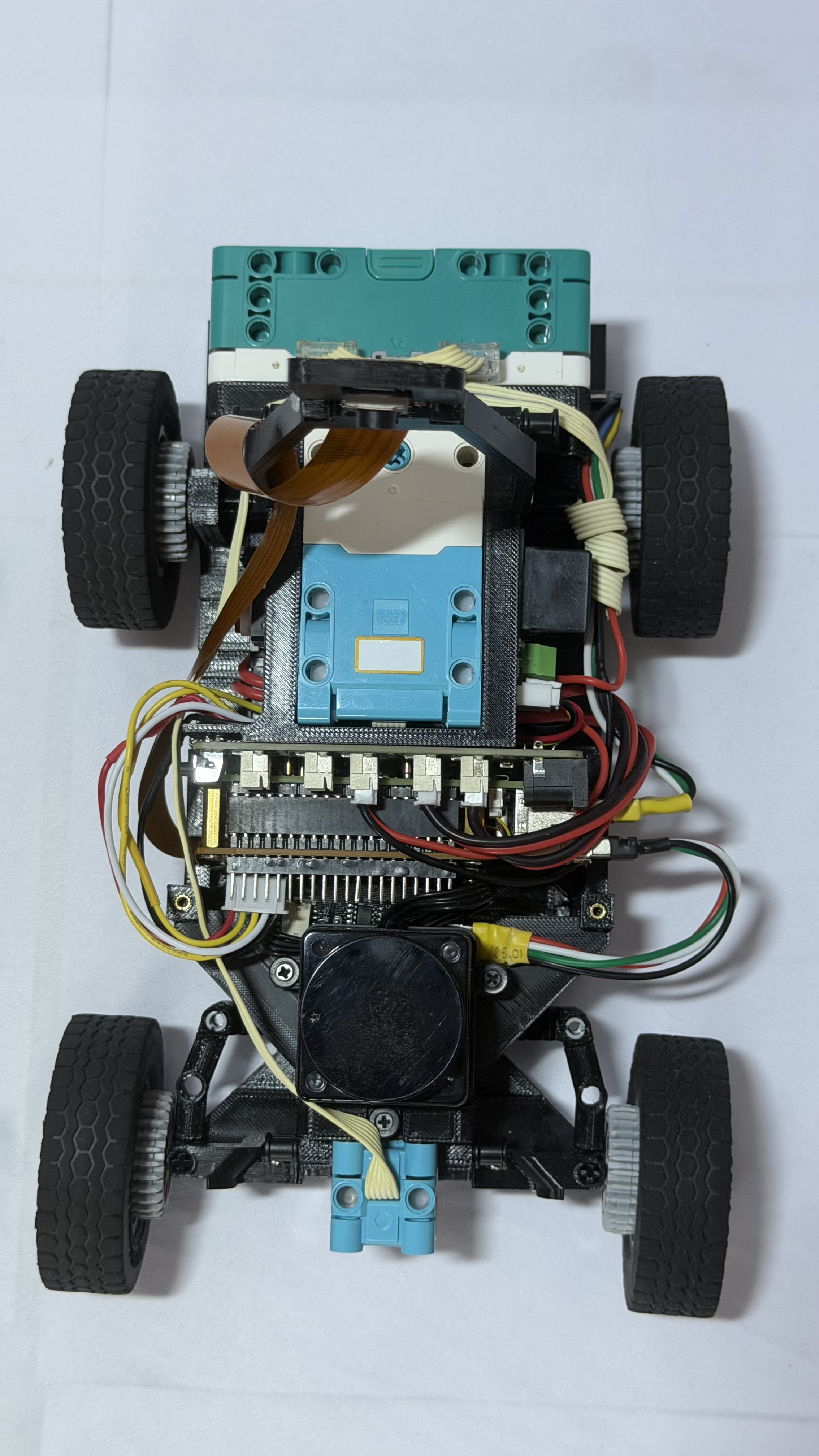
Top

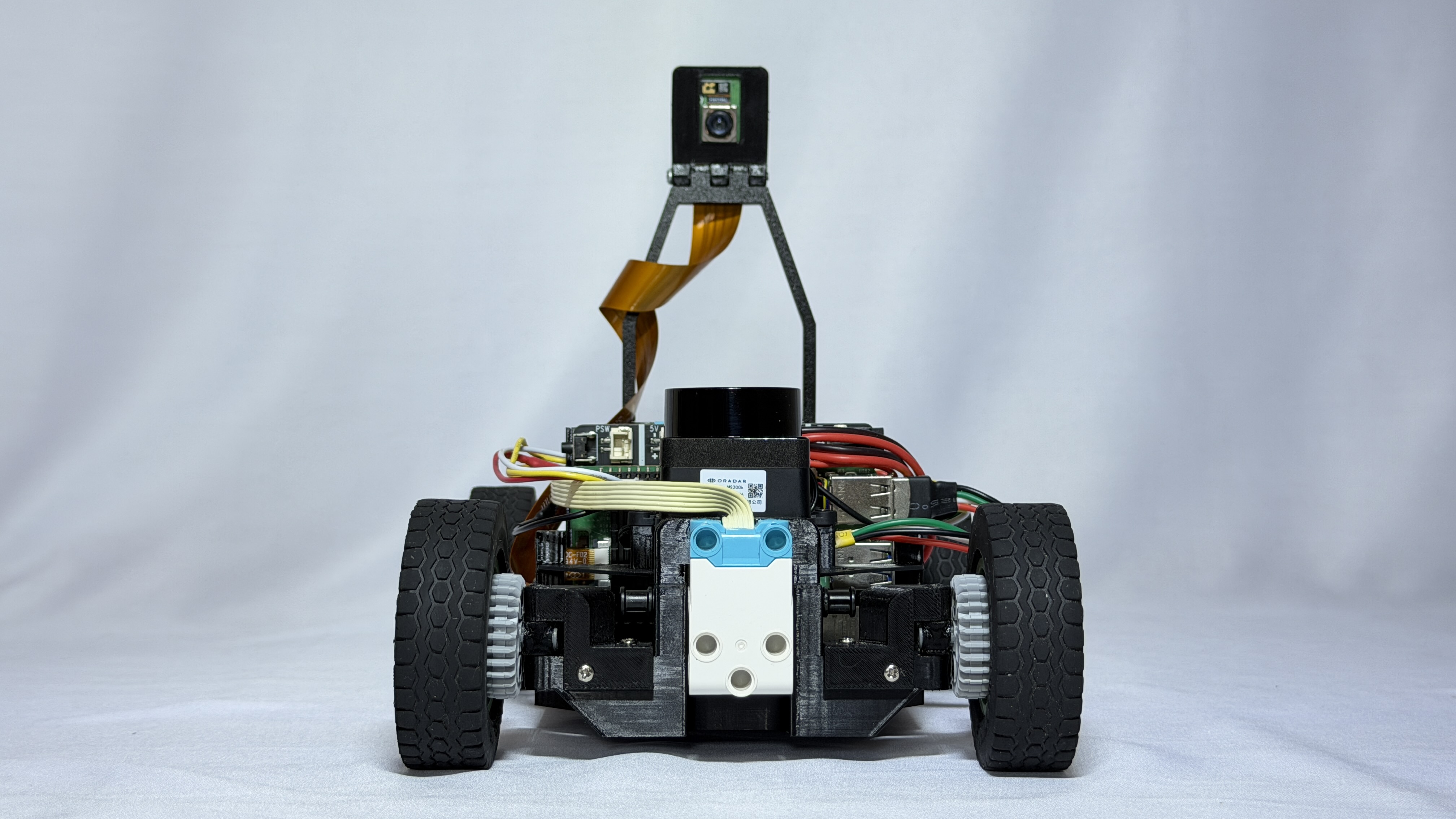
Front

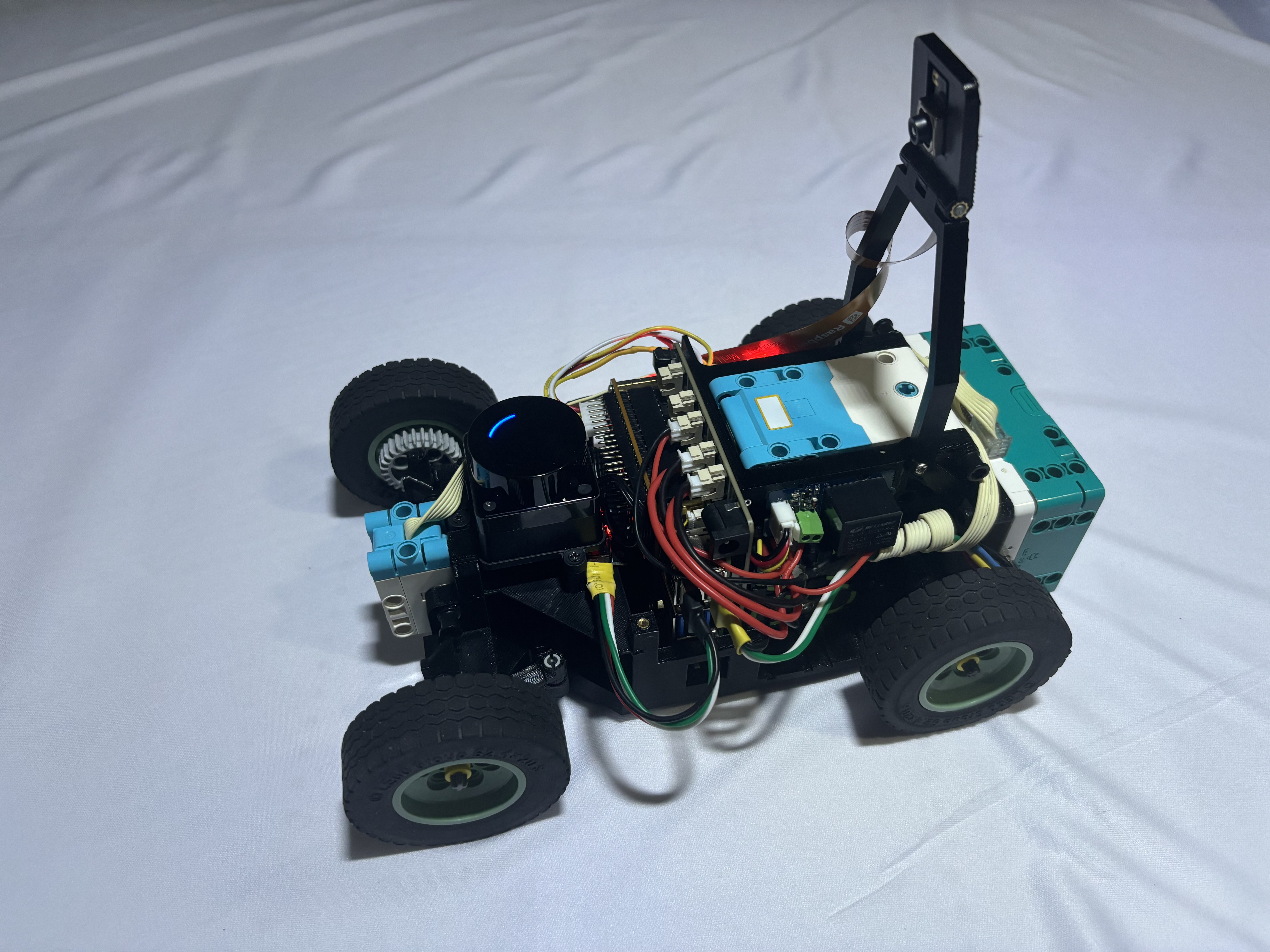
Left

Bottom
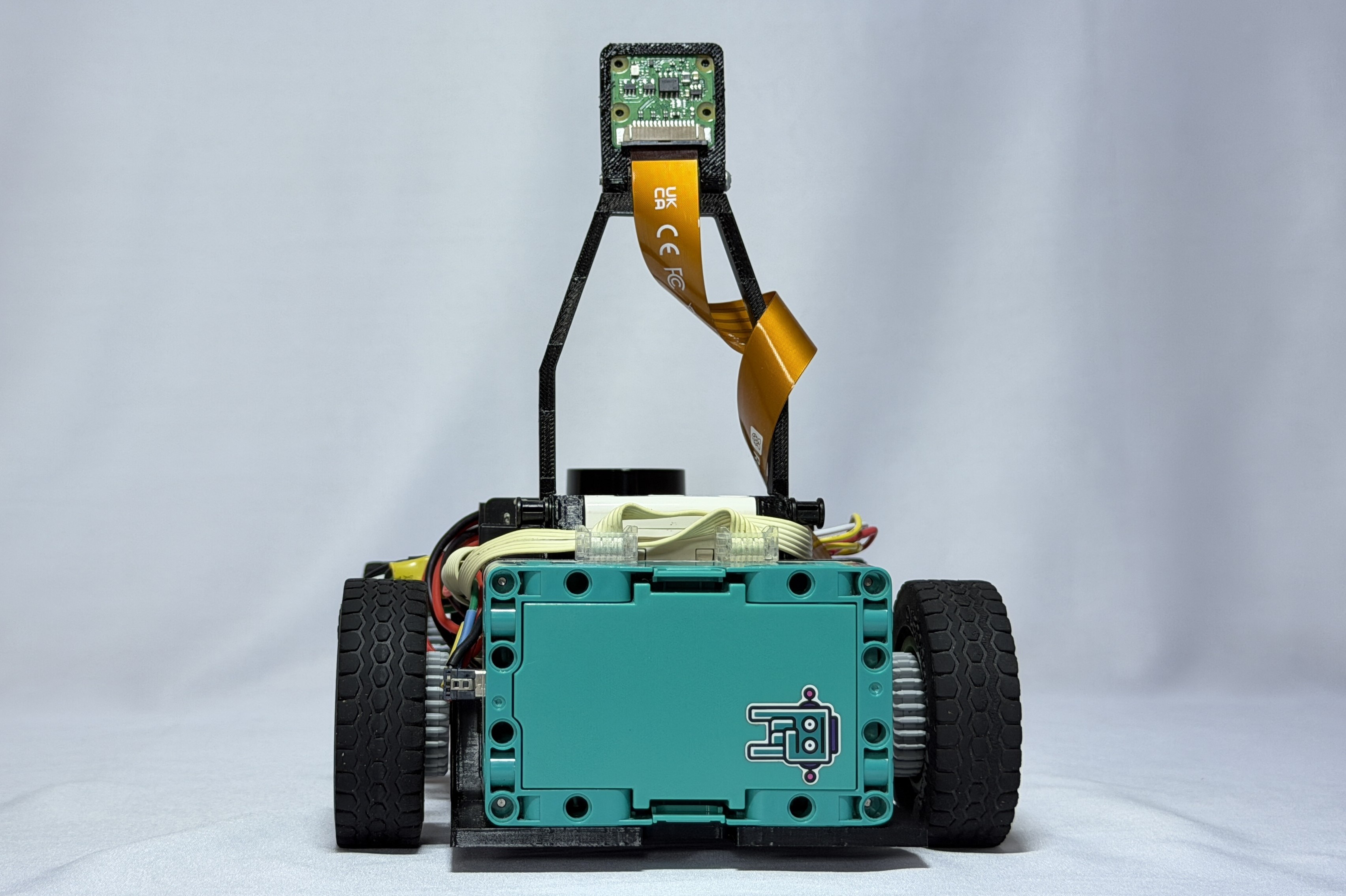
Back
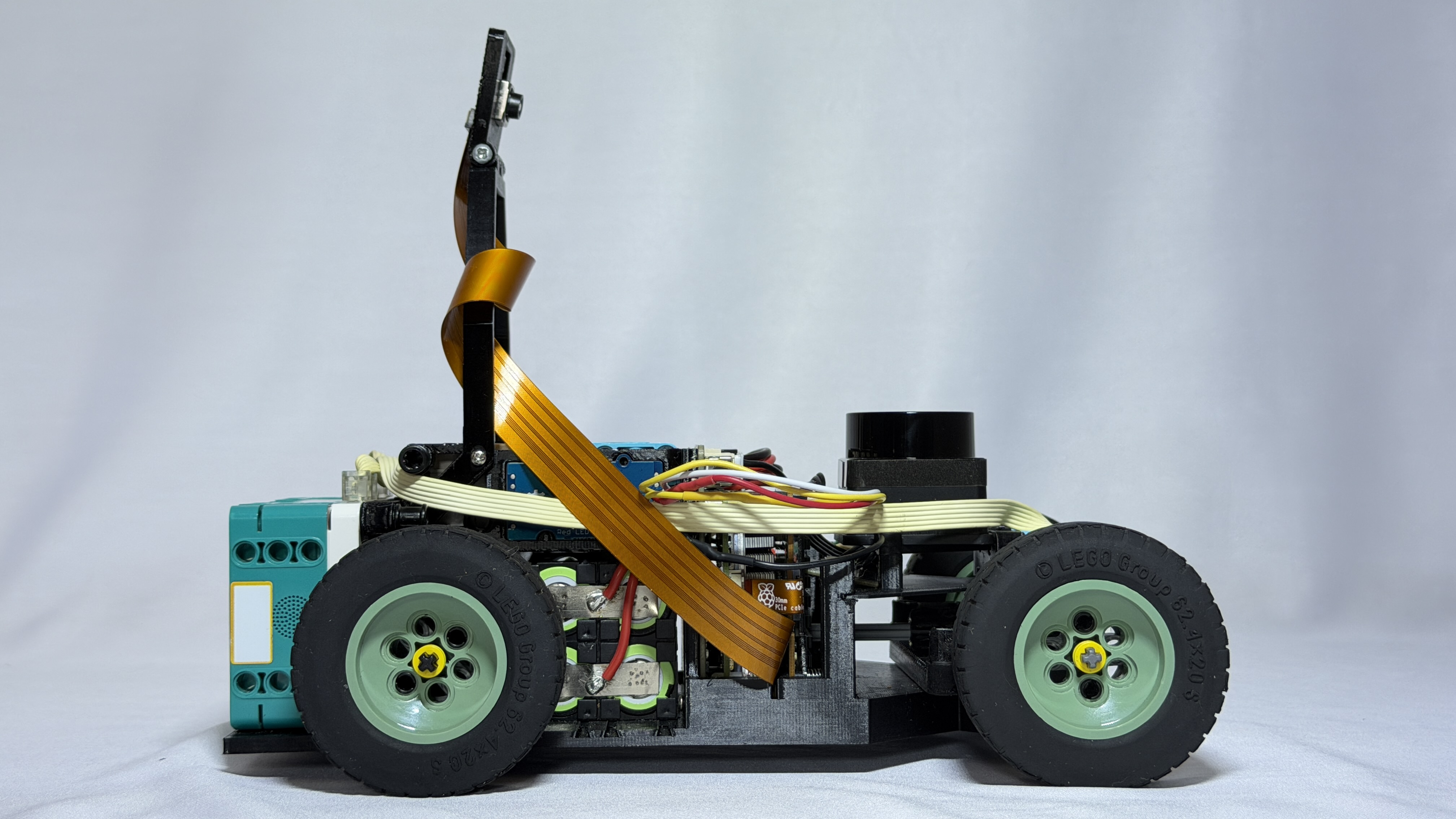
Right
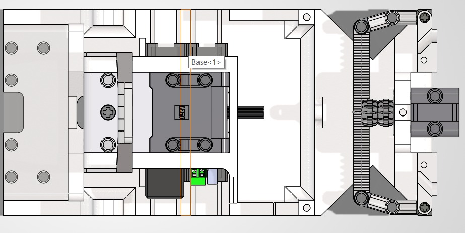
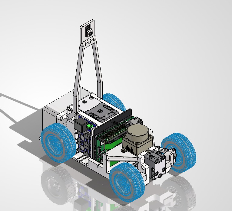
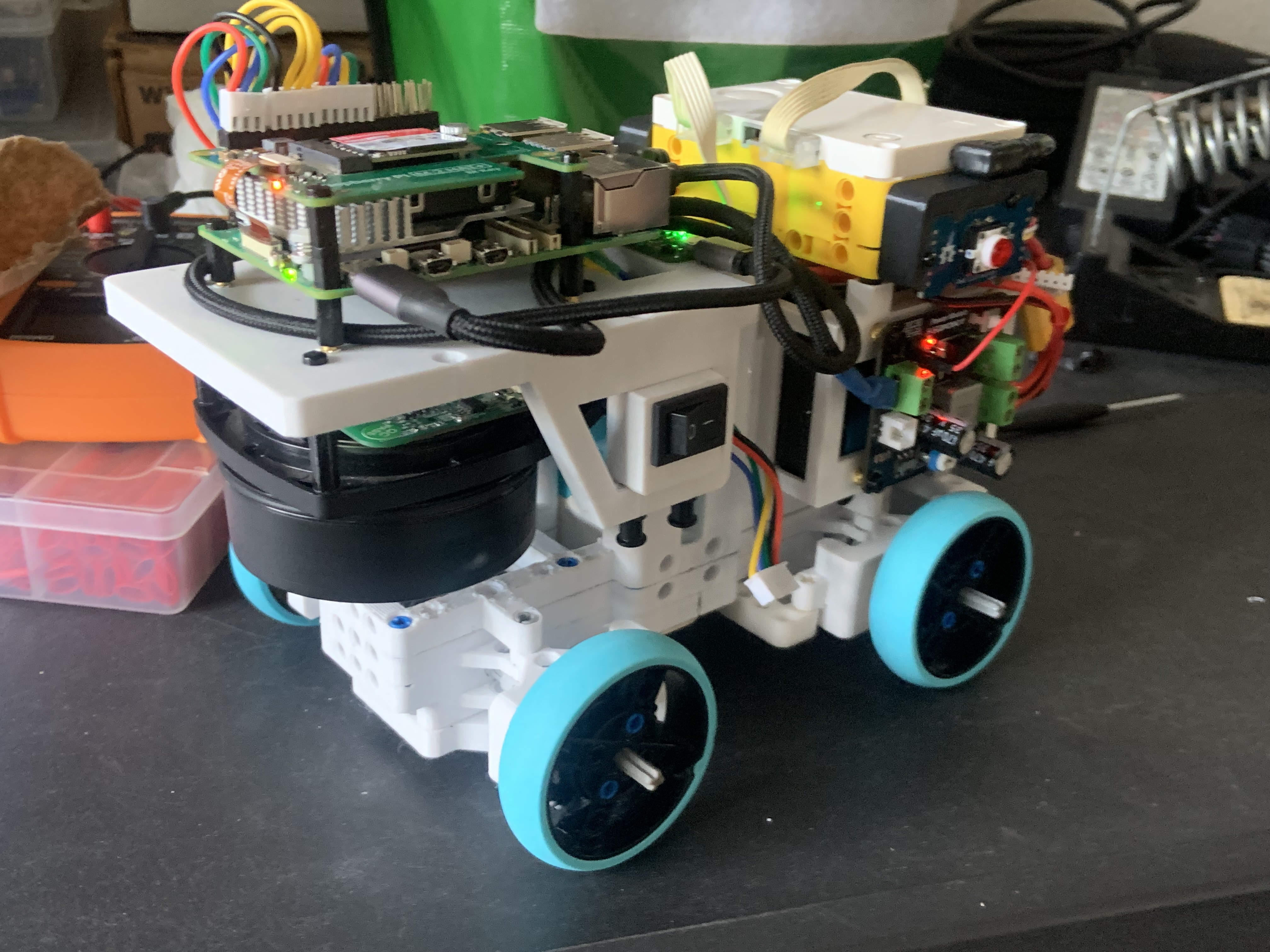
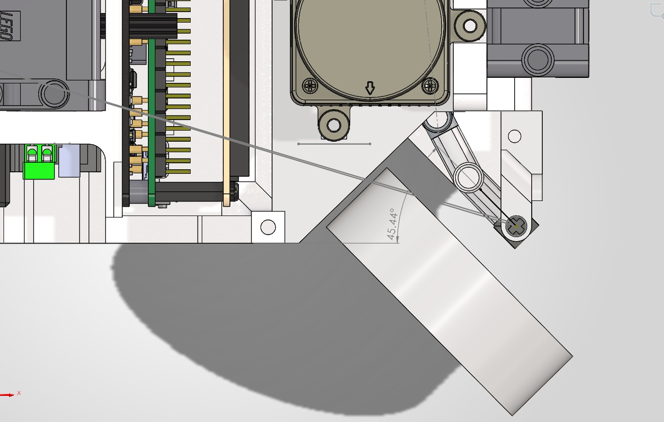
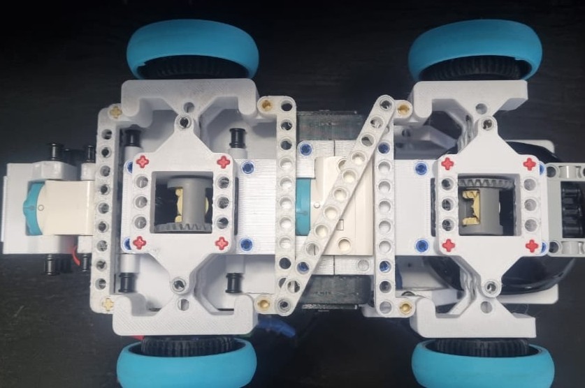
***"The Maker"*** is a rear-wheel-drive autonomous vehicle built around a fully custom, in-house 3D-printed chassis (designed in SolidWorks, printed on a Creality K1C) that repositions the battery pack and most components lower in the frame to lower the center of gravity and reduce weight transfer through corners. This year's chassis also trades the sharper-turning custom double-Ackermann steering geometry used in last year's prototype for a simpler regular-Ackermann, a deliberate trade-off made after trial and error showed the reliability gain outweighed the small loss in turning radius. A single LEGO SPIKE Large Angular Motor drives the rear axle while a LEGO SPIKE Small Angular Motor actuates the Ackermann steering, both commanded by a LEGO SPIKE Prime Hub, whose built-in IMU also supplies the robot's heading. Perception comes from a Orbbec Oradar MS200k LiDAR fused with a Raspberry Pi Camera Module 3 Wide accelerated by a Raspberry Pi AI HAT+ 2 (Hailo-10H, 40 TOPS). The LiDAR handles wall-following and obstacle range, the camera tracks the obstacles using a custom-trained YOLOv8n model (trained on our own labeled dataset and compiled to the Hailo-10H's `.hef` format) and classifies pillar colour, and this year's design drops the ultrasonic sensors, now using only the LiDAR and camera. All control and vision code runs in C/C++ on a Raspberry Pi 5, migrated from last year's Python codebase specifically to cut processing latency, and the whole robot is considerably lighter and more power-efficient than its predecessor: a smaller steering motor, a lighter AI/camera replacing an OAK-D Lite, and a 4-cell battery pack (down from 6 cells) sized to match the lower power draw. ### 3.1 Mobility Management #### Steering System The Maker's steering uses a regular Ackermann linkage, achieving a maximum steering angle of **45.44°**. This geometry ensures the inner and outer front wheels trace concentric arcs around a common turning center during a turn, minimizing tire scrub and keeping the front tires rolling rather than dragging through corners, a property that matters directly for both consistency and tire wear over a full run. Plan view of the current Ackermann steering system CAD model *Figure 1. Plan view of the current Ackermann steering linkage, showing the tie-rod and knuckle geometry.* CAD detail view showing the 45.44 degree Ackermann steering angle *Figure 2. Detail view of the CAD model highlighting the achieved maximum steering angle of 45.44°.* The Ackermann is actuated by a LEGO SPIKE Prime Small Angular Motor (Part 45607), commanded by the LEGO SPIKE Prime Hub. This is a change from previous seasons, where a medium angular motor was used: with this year's lighter chassis and reduced overall mass, the torque required to actuate the steering dropped enough that the smaller motor became sufficient, and switching to it freed up both weight and packaging space for other components. This regular Ackermann design also represents a deliberate step back from last year's steering geometry. In the previous season, the team implemented a custom double-Ackermann linkage, which allowed for a tighter turning radius but introduced mechanical inconsistencies and reliability flaws during testing. Bottom view of last year's robot showing the double Ackermann steering system *Figure 3. Bottom view of the previous season's robot, showing the double-Ackermann steering configuration used last year.* After weighing both options, the team concluded that the regular Ackermann's slightly wider turning radius was an acceptable trade-off given the reliability gained: it consistently completes every required turn on the WRO track, while eliminating the mechanical inconsistencies that affected the double-Ackermann design. #### Drivetrain This year's drivetrain also marks a layout change from last year's all-wheel-drive (AWD) configuration (see [Figure 3](other\additionalMedia\Others\Bottom2025.jpg)) to a rear-wheel-drive (RWD) layout. Driving only the rear axle simplified the drivetrain (removing the front differential/driveshaft hardware needed for AWD), reducing weight and mechanical complexity, while still providing enough traction for the WRO track once paired with the new LEGO 62.4×20S rubber tires. The vehicle uses a single LEGO SPIKE Large Angular Motor (Part 45602) driving the rear axle through a $20{:}28$ gear reduction ($R = 1.4$), turning LEGO $62.4 \times 20\text{S}$ rubber tires (Part 32019) ($r = 0.0312\text{ m}$). The motor and gear ratio were not assumed, they were sized against a full dynamic torque analysis targeting $a = 0.73\text{ m/s}^2$ over $t = 0.5\text{ s}$ to reach cruising speed.
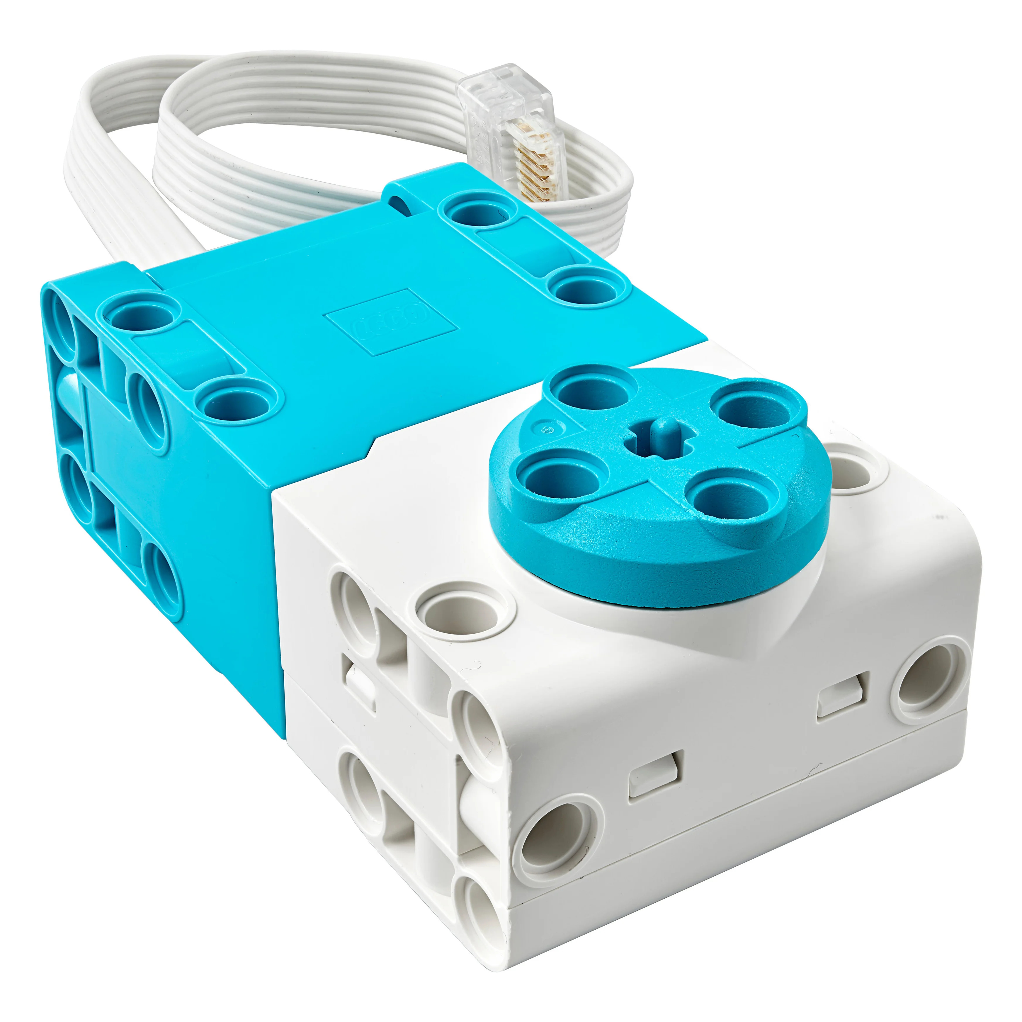
LEGO SPIKE Large Angular Motor (45602)

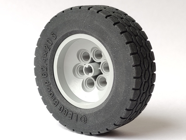
LEGO Tire 62.4 x 20 S (32019)
**Result:** at this operating point, the motor runs at only **33.8%** of its continuous max-efficiency torque capacity, reaching a loaded top speed of **0.365 m/s**, leaving a **66.2%** torque reserve for inclines or unexpected track perturbations. > ### Full torque & speed calculations > > #### 1. Design Inputs & Parameters > > | Parameter | Symbol | Value | Unit | > | :--- | :---: | :---: | :---: | > | Robot Mass | $m$ | $1.006$ | $\text{kg}$ | > | Wheel Diameter | $d$ | $0.0624$ | $\text{m}$ | > | Wheel Radius | $r$ | $0.0312$ | $\text{m}$ | > | Target Linear Acceleration ($t = 0.5\text{ s}$) | $a$ | $0.73$ | $\text{m/s}^2$ | > | Rolling Resistance Coeff. (Rubber LEGO $62.4 \times 20\text{ S}$) | $C_{rr}$ | $0.03$ | -- | > | Acceleration of Gravity | $g$ | $9.81$ | $\text{m/s}^2$ | > | Number of Drive Motors | $N$ | $1$ | -- | > | Gearbox Reduction Ratio ($20:28$) | $R$ | $1.4$ | -- | > | Gearbox Efficiency | $\eta$ | $0.85$ | -- | > > **2. Step-by-Step Derivation** > > **Step 1: Linear Acceleration Force ($F_{acc}$)** > > $$ > F_{acc} = m \cdot a = 1.006\text{ kg} \cdot 0.73\text{ m/s}^2 = 0.7344\text{ N} > $$ > > **Step 2: Rolling Resistance Force ($F_{rr}$)** > > $$ > F_{rr} = C_{rr} \cdot m \cdot g = 0.03 \cdot 1.006\text{ kg} \cdot 9.81\text{ m/s}^2 = 0.2961\text{ N} > $$ > > **Step 3: Total Linear Force ($F_{total}$)** > > $$ > F_{total} = F_{acc} + F_{rr} = 0.7344\text{ N} + 0.2961\text{ N} = 1.0305\text{ N} > $$ > > **Step 4: Total Wheel Torque ($T_w$)** > > $$ > T_w = F_{total} \cdot r = 1.0305\text{ N} \cdot 0.0312\text{ m} = 0.03215\text{ N}\cdot\text{m} > $$ > > **Step 5: Nominal Motor Torque ($T_m$)** > > $$ > T_m = \frac{T_w}{\eta \cdot R} = \frac{0.03215\text{ N}\cdot\text{m}}{0.85 \cdot 1.4} = 0.02702\text{ N}\cdot\text{m} \quad (\approx 2.70\text{ Ncm}) > $$ > > **Step 6: Motor Torque with Safety Factor ($T_{m,req}$)** > > A 25% safety margin ($1.25\times$) is applied to establish the minimum required torque of the traction motor, accounting for dynamic losses not captured above: > > $$ > T_{m,req} = T_m \cdot 1.25 = 0.02702\text{ N}\cdot\text{m} \cdot 1.25 = \mathbf{0.03377\text{ N}\cdot\text{m}} \quad (\approx 3.38\text{ Ncm}) > $$ > > **3. LEGO SPIKE Large Angular Motor (45602) Analysis & Speed Derivation** > > **3.1 Motor Technical Specifications (9V)** > > | Operating Condition | Torque ($\text{N}\cdot\text{m}$) | Torque ($\text{Ncm}$) | Speed ($\text{RPM}$) | Current ($\text{mA}$) | > | :--- | :---: | :---: | :---: | :---: | > | No Load | 0.0000 | 0.00 | 175 ± 15% | 135 ± 15% | > | Max Efficiency | 0.0800 | 8.00 | 135 ± 15% | 430 ± 15% | > | Stall Limit | 0.2500 | 25.00 | 0 | 1900 ± 15% | > > **3.2 Motor Operating Point & Load Analysis** > > **Continuous Duty Load (%)** (vs. Max Efficiency Point): > > $$ > \text{Load}_{\text{eff}} = \frac{T_m}{T_{\text{max-eff}}} \cdot 100 = \frac{2.70\text{ Ncm}}{8.00\text{ Ncm}} \cdot 100 = \mathbf{33.8}\verb|%| > $$ > > **Stall Limit Margin (%)** (vs. Stall Torque): > > $$ > \text{Load}_{\text{stall}} = \frac{T_m}{T_{\text{stall}}} \cdot 100 = \frac{2.70\text{ Ncm}}{25.00\text{ Ncm}} \cdot 100 = \mathbf{10.8}\verb|%| > $$ > > **3.3 Top Speed Derivation** > > **Step 1: Loaded Motor RPM** > > $$ > \text{RPM}_{\text{motor}} = \text{RPM}_{\text{no-load}} \cdot \left(1 - \frac{T_m}{T_{\text{stall}}}\right) = 175 \cdot \left(1 - \frac{2.702\text{ Ncm}}{25.00\text{ Ncm}}\right) = 156.1\text{ RPM} > $$ > > **Step 2: Loaded Wheel RPM** > > $$ > \text{RPM}_{\text{wheel}} = \frac{\text{RPM}_{\text{motor}}}{R} = \frac{156.1\text{ RPM}}{1.4} = 111.5\text{ RPM} > $$ > > **Step 3: Top Loaded Linear Speed** > $$v_{loaded} = \frac{\text{RPM}_{wheel} \cdot \pi \cdot d}{60} = \frac{111.5 \cdot \pi \cdot 0.0624}{60} = \mathbf{0.365\text{ m/s}}$$ > > **3.4 Technical Conclusion** > > With $a = 0.73\text{ m/s}^2$, the robot reaches its operational cruising speed of $0.365\text{ m/s}$ in exactly $0.5\text{ s}$. Operating at only 33.8% of the motor's continuous max-efficiency capacity ensures minimal thermal build-up and low current draw, leaving a 66.2% torque reserve to absorb unexpected track perturbations. #### Chassis Design The chassis is a fully custom, in-house design, modeled in SolidWorks and 3D-printed on a Creality K1C. This is a continuation of the team's own-design approach from previous years, refined for this iteration to package the electronics more densely and lower the center of gravity, positioning the battery pack and most of the main components lower in the frame. *Figure 4. Isometric view of the current chassis CAD model.* #### Assembly & Balance Repositioning the battery pack and heavier components (Raspberry Pi 5, UPS shield, LiDAR) lower in the frame was a deliberate choice to lower the chassis's center of gravity, reducing lateral weight transfer during high-speed cornering and improving mechanical traction without altering the Ackermann geometry itself. Component placement was also driven by the switch to a smaller, lighter camera/AI stack (Hailo-10H + Camera Module 3 Wide, replacing the OAK-D Lite) and a lighter 2-cell battery pack (replacing the previous 3-cell pack), both of which reduced overall mass and allowed tighter, more balanced packaging than in previous prototypes. --- ### 3.2 Power & Sense Management ### Sensors & Perception Units --- **Orbbec Oradar MS200k LiDAR**
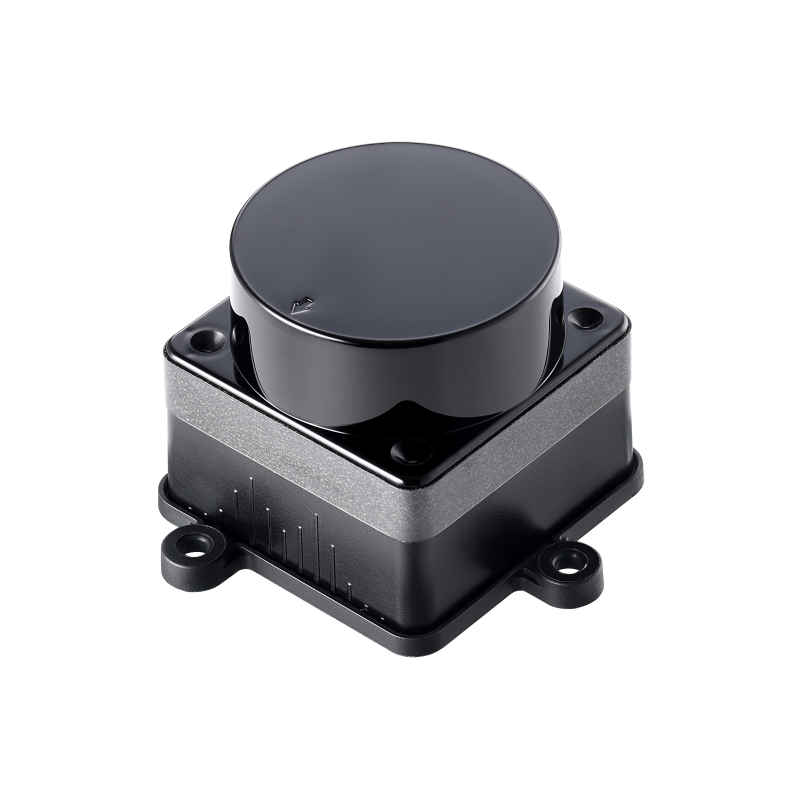
Provides a 360° distance scan around the robot, used for wall-following (perpendicular distance and orientation of the walls relative to the robot) and for measuring range to obstacles once they've been located by the camera. It replaces last year's Slamtec RPLiDAR S2L: after trial and error, it was chosen for being lighter and giving more reliable, less noisy distance readings. It connects to the Raspberry Pi 5 and feeds the wall-detection/line-fitting logic that drives the robot's navigation decisions. --- **Raspberry Pi Camera Module 3 Wide + Raspberry Pi AI HAT+ (Hailo-10H, 40 TOPS)**

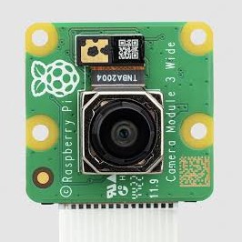
Raspberry Pi Camera Module 3 Wide

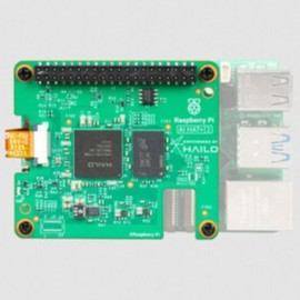
Raspberry Pi AI HAT+ 40 TOPS (Hailo-10H)
The camera captures the visual feed used to detect obstacle pillars and classify their color (red/green), while the Hailo-10H accelerator runs a custom-trained YOLOv8n model on-device to perform that detection/classification in real time. This pairing replaces last year's OAK-D Lite, chosen to reduce weight, power consumption, and response (inference) time while increasing overall efficiency. The camera's detections are fused with the LiDAR's distance data: the camera identifies what an obstacle is and roughly where, and the LiDAR supplies the precise distance needed to compute an avoidance vector. --- **LEGO SPIKE Prime Hub (built-in IMU)**

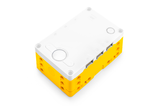
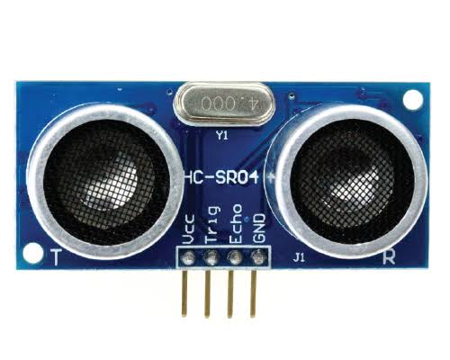
Rather than using a separate IMU module, the team relies on the SPIKE Prime Hub's built-in IMU to supply the robot's heading/orientation. The hub communicates with the Raspberry Pi 5 over a serial link, both relaying IMU readings and receiving motor commands for the drivetrain and steering. --- ### **(REMOVED)** **Ultrasonic sensors**

Ultrasonic sensors used in previous seasons were removed this year; the robot now relies entirely on the LiDAR and camera for perception, simplifying the sensor suite and reducing weight/power draw. --- ### Power Management The robot is powered by 4x Panasonic NCR18650B 3400mAh Li-ion cells (3.6 V nominal each), wired in a 4P (four cells in parallel) configuration through the Geekworm X1203 UPS shield, which also boost-converts the output to the 5.1 V required by the Raspberry Pi 5 and peripherals. **Total stored energy** $$C_{\text{total}} = 4 \cdot 3400\text{ mAh} = 13.6\text{ Ah}$$ $$E_{\text{total}} = 13.6\text{ Ah} \cdot 3.6\text{ V} = 48.96\text{ Wh}$$ **Theoretical battery life (worst case)** Under peak load, SLAM navigation and continuous computer vision inference, the components' estimated continuous power draw is: | Component | Operating State | Estimated Power | | :--- | :--- | :--- | | Raspberry Pi 5 | High CPU / OS load | 9.0 W | | Hailo-10H AI HAT | Active neural network inference | 4.0 W | | Orbbec Oradar MS200k LiDAR | Continuous scanning with spinning motor | 1.5 W | | Grove Modules | Relay (short pulses) + LED Button | 0.1 W | | **Total Load** | **Peak consumption at 5.1 V** | **14.6 W** | Accounting for the X1203 boost converter's ~90% efficiency ($\eta = 0.90$): $$P_{\text{input}} = \frac{14.6\text{ W}}{0.90} \approx 16.22\text{ W}$$ $$I_{\text{battery}} = \frac{16.22\text{ W}}{3.6\text{ V}} \approx 4.51\text{ A}$$ > **Hardware Design Note:** Distributed across 4 parallel cells, this is an average of 1.13 A per cell, well within the NCR18650B's 4.8 A continuous discharge limit, avoiding thermal stress and premature degradation. $$t_{\text{runtime}} = \frac{48.96\text{ Wh}}{16.22\text{ W}} \approx 3.01\text{ hours}$$ **Real-world battery life (measured)** Physical testing recorded a steady current draw of 0.667 A per connector (each connector groups two cells in parallel), totaling 1.334 A at 5 V across the full integrated system. $$P_{\text{output}} = 1.334\text{ A} \cdot 5\text{ V} = 6.67\text{ W}$$ $$P_{\text{input}} = \frac{6.67\text{ W}}{0.90} \approx 7.41\text{ W}$$ $$t_{\text{runtime}} = \frac{48.96\text{ Wh}}{7.41\text{ W}} \approx 6.6\text{ hours}$$ > **Conclusion:** Under real-world operating conditions, the robot runs continuously for approximately 6.5 hours before fully depleting the battery bank, well above the theoretical worst-case estimate, since sustained peak CPU/inference load is rarely held continuously in practice. **Design limitation: charging & hot-swapping** A drawback of this configuration is that the batteries charge internally, in place, via the X1203 board. The current assembly makes keeping a pre-charged spare set for a quick hot-swap impractical, since swapping cells requires partially disassembling the chassis, a depleted robot must instead be plugged in to recharge, which is a limitation for quick turnaround between test/competition runs. --- ### Processing Architecture & Microcontrollers The robot's control loop is centered on the Raspberry Pi 5, which fuses two independent sensor streams and issues motor commands accordingly. The Orbbec Oradar MS200k LiDAR streams a 360° distance scan over serial, feeding the wall-following and obstacle-range logic. In parallel, the Raspberry Pi Camera Module 3 Wide streams frames that are run through a custom-trained YOLOv8n model accelerated by the Hailo-10H AI HAT, detecting obstacle pillars and classifying their color. The Raspberry Pi 5 fuses both streams (camera identifies *what* and roughly *where*, LiDAR gives the precise distance) and, running all control and vision code in C/C++ for low latency, computes the next steering/drive action. Motor and steering commands are sent over a serial (USB) link to the LEGO SPIKE Prime Hub, which actuates the Large Angular Motor (drivetrain) and Small Angular Motor (steering). The Hub's built-in IMU also reports heading back to the Raspberry Pi 5, closing the loop for orientation-aware navigation. Separately, the Raspberry Pi's GPIO pins handle the start button, status LED, and a relay that powers the SPIKE Hub on at boot, these run independently of the main sensor/control loop. Diagram of how the LiDAR, camera, Hailo-10H, Raspberry Pi 5, SPIKE Prime Hub, and motors are interconnected *Figure 5. Data flow between the robot's sensors, processing units, and actuators.* --- ### Hardware Schematics & PCB Design Connections Schematics *Figure 6. System wiring diagram showing power distribution (Geekworm X1203 UPS board from the 2S2P 18650 battery pack) and data connections between the Raspberry Pi 5, Camera Module 3 Wide (CSI), Hailo-10H AI HAT (PCIe), Oradar MS200 LiDAR (USB), LEGO SPIKE Prime hub (USB, driving the drive and steer motors), the GPIO-controlled start button/status LED (Grove LED-Button), and the Grove Relay that switches 5V power to the SPIKE hub.* No custom PCB was implemented in this prototype; the full system wiring is documented in the connections schematic above (*Figure 6*), and all components are connected via their stock breakout boards/shields (Geekworm X1203, Grove modules, etc.) and standard wiring. Schematics for a custom PCB are still in development and not yet implemented in the robot; they are kept at [`schemes\hardware\pcb`](schemes/hardware/pcb) and may be adopted in a future revision if the team qualifies for the international stage. --- ### Wireless Communication & Telemetry During development, the team connects to the Raspberry Pi 5 primarily over SSH, occasionally through RealVNC Viewer when a full graphical display is needed, or through a direct terminal connection when the display is not required. This is normally done wirelessly for convenience during testing. However, since the WRO Future Engineers competition prohibits wireless connections to the robot, the team connects via a wired Ethernet connection instead during the competition itself, to remain compliant with that rule while still allowing SSH access for setup and debugging between runs. --- ### 3.3 Obstacle Management & Control Strategy #### System & Software Architecture All control and vision code runs in C++ on the Raspberry Pi 5, paired with the Hailo-10H AI HAT for on-device inference. The main application (`object_detection`) is structured as a set of cooperating threads: a Hailo preprocess → inference → postprocess pipeline handling camera frames, a background Oradar lidar reader thread continuously filling a 360-slot distance buffer, and an `Obstacle_Challenge_Thread` that runs the navigation/avoidance decision logic and issues motor commands over serial to the LEGO SPIKE Prime Hub. Software data flow diagram: sensors, processing, decision, and actuators *Figure 7. Software data flow from sensor input through processing and decision-making to motor actuation.* ## Open Challenge Program Flow Unlike the Obstacle Challenge, the Open Challenge runs a separate, simpler program [`src\ondevice\main.cpp`](src/ondevice/main.cpp). There are no color pillars to detect, so the Hailo/camera pipeline isn't used at all, only the LiDAR and the SPIKE Prime Hub. The trace below follows `main()` top to bottom. The robot's own left/right turns are true mirror images of each other in the code, drawn once here as `sentido` (the detected open side), with the mirror called out in the caption below. ```mermaid flowchart TD A(["Power on"]) --> B["Init lidar + writer thread
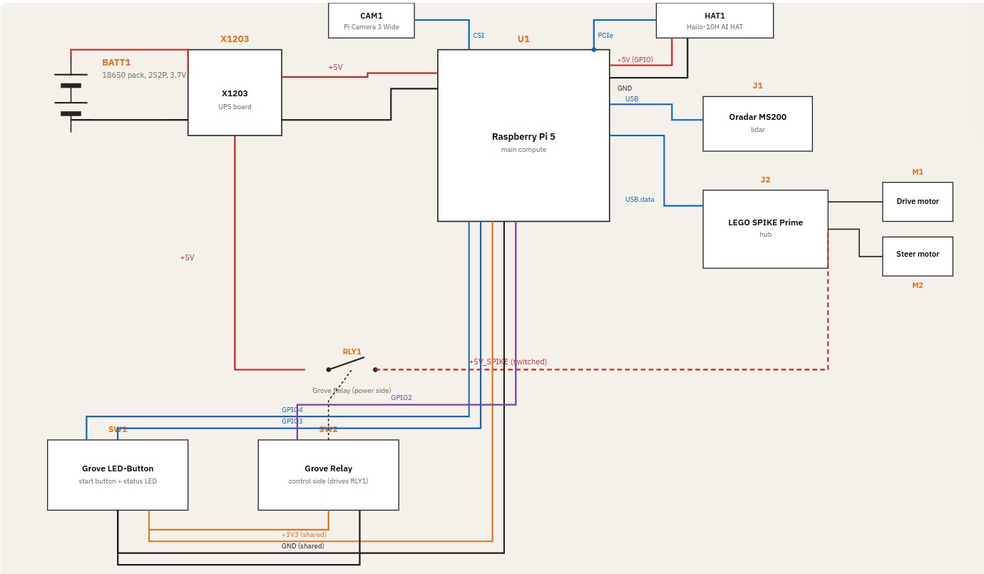
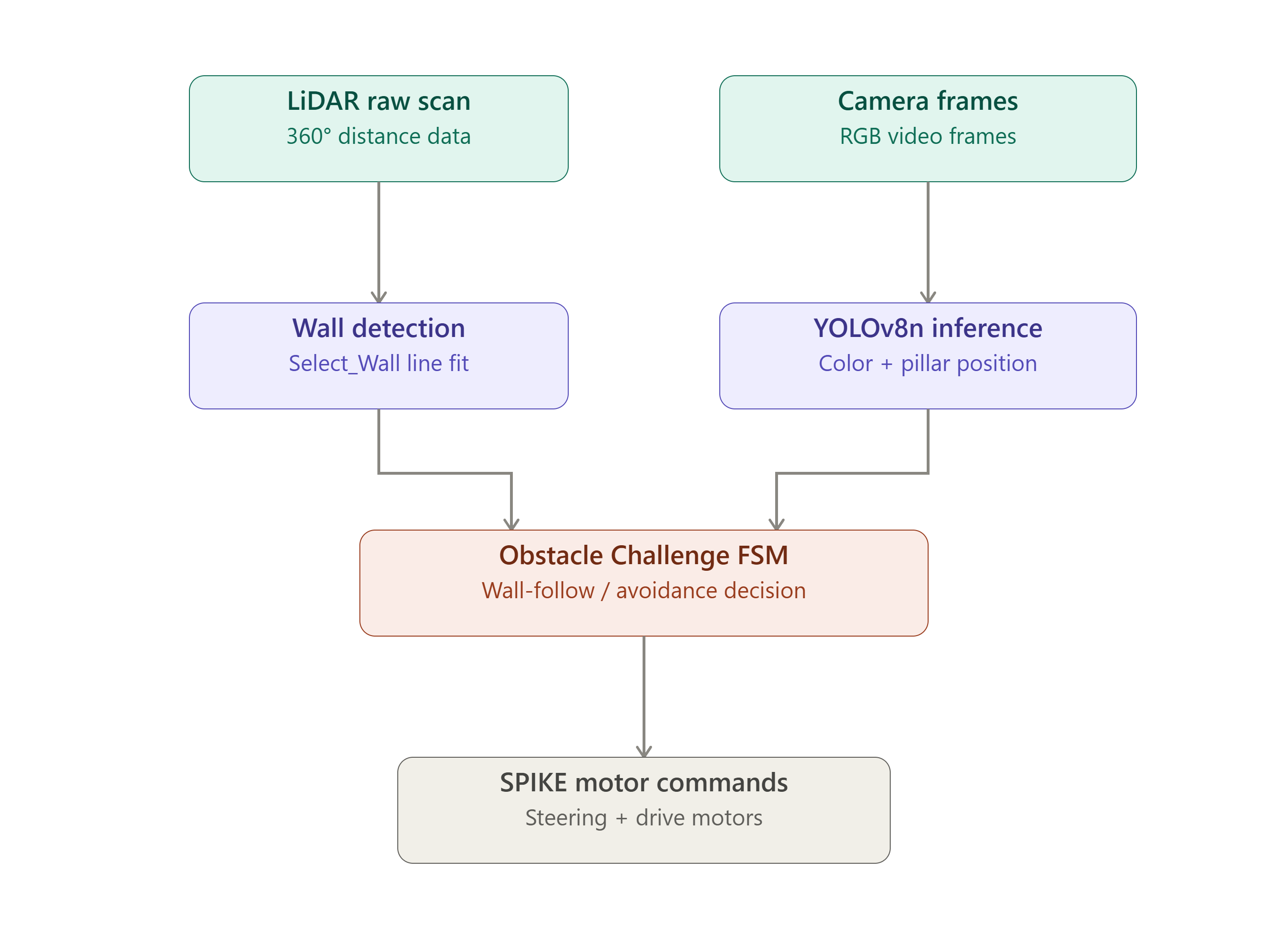
Init GPIO, power on SPIKE hub
SPIKE serial + interpreter,
load on-hub motion routines"] B --> C{{"Wait for start button"}} C --> D["Reset gyro to 0°
Center vehicle"] D --> E["Read lidar once:
front / right / left distance"] E --> F{"right or left
> 800 mm?"} F -- yes: OUTSIDE start --> G["First straight = 1350 mm"] F -- no: INSIDE start --> H["First straight = 300 mm"] G --> I["Detect which side is open:
Advance_And_Detect_Side()
→ sentido = right | left"] H --> I I --> J["Turn 80° toward sentido
Center vehicle"] J --> K["Drive the first-straight distance,
curving toward sentido"] K --> L["Slope() at +300 mm,
Slope() again at +700 mm more"] L --> M["Average the two slopes
Reset gyro to that heading"] M --> N(["Corner loop
v = 0 … 9"]) N --> O["Advance until a gap opens
on the sentido side"] O --> P["Turn 80° toward sentido
Center vehicle"] P --> Q["Drive 300 mm, then 700 mm more,
measuring + averaging slope again"] Q --> R["Reset gyro to the new heading"] R --> S{"v = 10?"} S -- "no (v++)" --> N S -- yes --> T["Pick a stop distance from the
opposite-side reading taken back
at the start (400 / 600 mm bands)"] T --> U["Turn 80° toward sentido, center
Drive 300 mm"] U --> V{"front reading
> 1500 mm?"} V -- yes --> W1["Advance to 1750 mm from wall"] V -- no --> W2["Advance to 1400 mm from wall"] W1 --> X["Coast motors · close serial
stop lidar thread · close lidar"] W2 --> X X --> Z(["Run finished"]) ``` *Figure 8. Open Challenge program flow, traced directly from [`src\ondevice\main.cpp`](src/ondevice/main.cpp).* > Every turn, distance, and threshold above is read directly out of [`main.cpp`](src/ondevice/main.cpp). **Sentido** (the detected open side) is fixed for the whole run right after the first turn, the code for `sentido = left` is the exact sign-mirrored twin of the `right` path drawn here. ### High-Level States The same run, one level up, the states a judge or teammate would actually watch the robot move through. ```mermaid stateDiagram-v2 [*] --> Booting Booting --> WaitingForStart: hardware + hub ready WaitingForStart --> Calibrating: start button pressed Calibrating --> SideDetect: gyro zeroed, vehicle centered SideDetect --> Aligning: open side found (left / right) Aligning --> Cornering: heading corrected to wall Cornering --> Aligning: gap found, turned (x10) Cornering --> Parking: 10th corner cleared Parking --> Stopped: final wall reached WaitingForStart --> Stopped: Ctrl+C Calibrating --> Stopped: Ctrl+C SideDetect --> Stopped: Ctrl+C Aligning --> Stopped: Ctrl+C Cornering --> Stopped: Ctrl+C Stopped --> [*] ``` *Figure 9. Open Challenge high-level state machine.* > Ctrl+C sets the lidar's `terminating` flag from every state; the current busy-wait loop notices it within ~1 ms and the run drops straight to **Stopped** instead of finishing the maneuver in progress. ### Thresholds Pulled straight from the constants in [`main.cpp`](src/ondevice/main.cpp), for whoever tunes this next. | Constant | Value | Where it acts | |---|---|---| | Outside / inside split | `800 mm` | Right or left reading above this at the very start, treated as an "outside" starting box, else "inside". | | First straight, outside case | `1350 mm` | Distance driven right after the first turn, before the first slope measurement. | | First straight, inside case | `300 mm` | Same step, shorter start, inside boxes give less room before the first wall. | | Slope sampling gap | `300 + 700 mm` | Two `Slope()` reads this far apart get averaged into one heading correction. | | Corners per run | `10 (v < 10)` | Loop count for the corner-navigation phase, matches the Open Challenge's three laps of the four-cornered field. | | Corner turn angle | `80°` | Every `Spike_Turn_For_Degrees` call at a corner, in both the lap loop and the setup turn. | | Final approach bands | `400 / 600 mm` | The opposite-side reading from step 1 selects a 550, 750, or 1050 mm stop distance for parking. | | Final front threshold | `1500 mm` | Chooses whether the closing approach stops at 1400 or 1750 mm from the front wall. | --- ## Obstacle Challenge flow Two threads run at once (both started from `main()`): the Hailo camera pipeline keeps the global `traffic_lights` struct (color, x-position, area, confidence) updated in the background, while `Obstacle_Challenge_Thread` drives the robot and reads that struct whenever it needs to know what cube it's currently looking at. The diagrams below are the navigation thread. ### High-level states ```mermaid stateDiagram-v2 [*] --> Booting Booting --> WaitingForStart: lidar + GPIO + Spike + Hailo model ready WaitingForStart --> InitialScan: start button pressed InitialScan --> ClockwiseRun: right-side reading > 600mm InitialScan --> CounterClockwiseRun: left-side reading > 600mm ClockwiseRun --> ExitParkingLot: estacionamiento_clockwise() CounterClockwiseRun --> ExitParkingLot: estacionamiento_counterclockwise() ExitParkingLot --> CornerCycle CornerCycle --> CornerCycle: x12 total -- 3 laps x 4 corners (4th of each lap runs parking=true) CornerCycle --> Idle: 12 corners complete Idle --> Stopped: Ctrl+C WaitingForStart --> Stopped: Ctrl+C InitialScan --> Stopped: Ctrl+C CornerCycle --> Stopped: Ctrl+C Stopped --> [*] ``` > The direction of the run is fixed for the whole attempt by the single > side-wall reading taken in `InitialScan`, and both branches feed the same > `ExitParkingLot` → `CornerCycle` sequence. The counter-clockwise path is > the sign-mirrored twin of the clockwise one, so the corner cycle below is > drawn once rather than twice. ### One corner cycle (repeats x12) `Corner_Case` and `Desicion` together are the unit that repeats 12 times. Drawn once here rather than 12 times over. ```mermaid flowchart TD A(["Corner_Case(past_cube, parking)"]) --> B["Advance to 1100mm from the front wall"] B --> C["Read the cube color the camera
currently sees: traffic_lights.light_color"] C --> D{"cube color?"} D -- green --> E["Advance to 600mm (parking)
or 400mm (not parking)"] D -- red --> F["Advance to 990mm"] D -- none --> G["Advance to 650mm
set is_middle_case from the PREVIOUS cube's color"] E --> H["Turn 86° into the next section
(right clockwise, left counter-clockwise),
center vehicle, coast"] F --> H G --> H H --> I(["Desicion(cube, is_middle_case, parking)"]) I --> J["Sleep 1s, then Slope() on the outer wall
reset gyro +/-90deg to square up to the side wall"] J --> K{"was a cube already
seen right at the corner?"} K -- "no (color was none)" --> L{"is_middle_case?"} L -- yes --> M["esquivar_cubos_middle(parking)
one cube in the middle of the section"] L -- no --> N["esquivar_cubos_1(parking)
avoid the first cube"] N --> O["esquivar_cubos_2(result, parking)
look for + avoid a second cube"] K -- yes --> O M --> P(["result feeds the NEXT Corner_Case call as past_cube"]) O --> P ``` > `esquivar_cubos_1/2/middle` each call `calculte_angle_section_start_clockwise_chr` > (or its `..._counterclockwise` counterpart) to get an angle + distance to the > cube, turn toward it (left for green, right for red -- the passing side is set > by the rules and does not mirror with the driving direction), advance alongside > it, then small-turn back straight. > `esquivar_cubos_2` additionally short-circuits to a plain 1000mm advance > when no second cube is present or it's the same color as the first. > `Obstacle_Challenge_Thread` also calls `Slope(front)` once, right after > the initial button-press reset, but resets the gyro to a hardcoded `0` > right after rather than to that `slope` value -- the measurement is taken > but its result currently isn't used. ### Thresholds referenced above | Constant | Value | Where it acts | |---|---|---| | Direction-of-run split | `600 mm` | Right reading above this at start -> clockwise run; left reading above this -> counter-clockwise run. Fixed for the whole attempt. | | Corner approach | `1100 mm` | First advance in every `Corner_Case`, before reading the cube color. | | Green-cube advance | `600 mm` (parking) / `400 mm` (not) | Second advance in `Corner_Case` when the corner cube is green. | | Red-cube advance | `990 mm` | Second advance in `Corner_Case` when the corner cube is red. | | No-cube advance | `650 mm` | Second advance in `Corner_Case` when no cube is seen at the corner. | | Corner turn | `86 deg` | Every `Corner_Case`, turning into the next section: right when running clockwise, left when running counter-clockwise. | | Gyro realign | `Slope(outer wall) +/- 90 deg` | Start of every `Desicion`, squares the robot to the outer side wall (on the left running clockwise, on the right running counter-clockwise) before looking for cubes. | | Corners per run | `12` (3 laps x 4) | 4th corner of each lap calls `Corner_Case`/`Desicion` with `parking=true`. | | Cube-1 clearance | `hypotenuse - 400` (normal) / `-100` (parking, red) | `esquivar_cubos_1`'s advance-past-cube distance. | | Cube-2 clearance | `hypotenuse - 400` (normal) / `-150` (parking, green-cube case) | `esquivar_cubos_2`'s advance-past-cube distance. | --- #### LiDAR & Perception Processing Wall and corner detection (`Select_Wall()`) follows this pipeline on each call: 1. **Angular windowing**, a 70°-wide window centered on the requested side (front/right/left/behind), with the innermost ±3° excluded to avoid seam/corner noise. 2. **Chassis filtering**, any return closer than 150 mm is discarded as the robot's own body, not an environmental wall. 3. **Radius Outlier Removal (ROR)**, a point is dropped if it has fewer than 3 neighbors within 300 mm (with 15° of padding outside the window so edge points aren't unfairly penalized). 4. **Segmentation**, the remaining points are split into candidate walls wherever consecutive points jump apart by more than 60 mm (gap-based segmentation), then further split at corners using a recursive max-perpendicular-deviation method (Iterative End-Point Fit) with a 40 mm threshold. 5. **Scoring**, a segment only qualifies as a wall if it has at least 6 points, spans at least 200 mm end-to-end (to reject compact objects/blocks), and has an RMS perpendicular residual under 15 mm against its own best-fit line (computed via Total Least Squares/PCA, since it has no bias toward any orientation). 6. **Per-side tracking**, once a wall is chosen for a side, subsequent frames prefer to keep following that same physical wall (matched within 300 mm position / 20° orientation) rather than re-snapping every frame. Green/red pillar identification is handled by the camera + Hailo-10H YOLOv8n pipeline described in §3.2, which classifies pillar color directly from the RGB frame. The LiDAR's role is purely geometric: once a pillar is flagged by vision, the LiDAR supplies the precise distance/angle used to compute the avoidance vector. #### Sensor Fusion & Heading Estimation Heading is provided primarily by the LEGO SPIKE Prime Hub's built-in gyroscope, read and reset via serial commands (`spike.cpp`). This gyro reading is the robot's main orientation reference throughout a run. LiDAR data supplements this in specific situations rather than being continuously fused with the gyro. During particular maneuvers, wall-orientation readings from the Oradar LiDAR (`Slope()`, `Correction_For_Triangles_Left/Right`, `Advance_And_Measure_Left/Right_Slope`) are used to correct the robot's position and alignment against the track walls. It's worth being precise about what this is: it is **not** a formal sensor fusion implementation. There is no complementary filter, Kalman filter (EKF), or other algorithm combining the gyro and LiDAR signals into a single fused heading estimate. The architecture is better described as **gyro-primary heading with situational LiDAR-based positional correction**, the SPIKE gyro drives orientation continuously, and the LiDAR steps in at defined points in the maneuver logic to correct drift or misalignment against a known wall reference. #### Trajectory Control & Closed-Loop Steering Steering uses a Proportional-Derivative (PD) controller: the P term reacts to the lateral position error, and the D term anticipates the rate of change of that error to damp oscillations, allowing smooth trajectories through both the wall-following and obstacle-avoidance challenges. Two separate PD loops are tuned for the two control contexts: | Controller | Kp | Kd | | :--- | :---: | :---: | | Camera-based cube following | 150 | 100 | | Gyroscope-based wall following | 2 | 300000 | Both gain sets were obtained through trial-and-error tuning on the physical track rather than derived analytically. #### Avoidance & Navigation Logic * **Passing Rules:** Green → pass on left | Red → pass on right * **Underlying logic:** pillar color decisions are handled by `Desicion()`/`Corner_Case()`, and the actual avoidance maneuvers are implemented as `esquivar_cubos_1`/`esquivar_cubos_2`/`esquivar_cubos_middle` and `avoid_cube_start_section`, which use angle/hypotenuse geometry (`calculte_angle_section_start_clockwise[_chr]`, `calculte_angle_section_start_counterclockwise`) to aim the robot's approach at each detected pillar's position. * **Parallel Parking Maneuver:** The camera detects the magenta parking lot markers (labeled `x-parking`) to locate the parking zone. The robot then uses the LiDAR to position itself at a set distance from the wall, and from there uses a combination of LiDAR and gyroscope readings to execute the parking maneuver itself. #### State Machine & Safety Systems * **Robot States:** The `Obstacle_Challenge_Thread` state machine runs: `Booting` → `WaitingForStart` (waits for LiDAR, GPIO, SPIKE hub, and the Hailo model to be ready, then the start button) → `InitialScan` (reads the side-wall distance to pick a direction) → `ClockwiseRun` or `CounterClockwiseRun` → `ExitParkingLot` → a repeating `CornerCycle` (12 total: 3 laps × 4 corners, with the 4th corner of each lap run in parking mode) → `Idle` once all 12 corners are complete → `Stopped` (reachable from any state via Ctrl+C). The direction is decided once in `InitialScan` and held for the whole attempt; the two directions run the same corner cycle with mirrored turn signs and side-wall references. * **Safety Systems:** `rasp_gpio.cpp` implements a start button (`Rasp_Gpio_Wait_For_Button`) and a status LED, plus a relay that powers on the SPIKE hub at boot. There is no dedicated hardware emergency-stop button separate from process termination (Ctrl+C), and no automatic sensor-failure fallback is implemented. The gyroscope and LiDAR do serve as the robot's recovery mechanism: at the start of every corner's decision logic, the robot re-squares its gyro heading against the LiDAR-measured side wall (`Slope(left)`, ±90°), correcting any drift accumulated during the previous cube-avoidance maneuver before continuing. --- ## 4. Engineering Process & Design Iterations >**Full engineering journal:** [`Engineering_Journal_CSS_WRO2026.pdf`](Engineering_Journal_CSS_WRO2026.pdf) > >The summary below is deliberately short. The complete account, design reasoning, tradeoff and risk registers, power and torque budgets, the dated logbook, and photographs of every prototype, is in the journal. ### Prototype Evolution "The Maker" is the **sixth** distinct vehicle the team has built across two seasons. The break between the two seasons was deliberate: the 2026 car is not an incremental descendant of the 2025 one. | # | Season | Design | Outcome / reason for the next step | | :--- | :--- | :--- | :--- | | v1 | 2025 | Hybrid LEGO Technic chassis | Fast to iterate, but component placement was dictated by the Technic hole grid and the assembly had play at every joint | | v2 | 2025 | Fully custom 3D-printed chassis, double-Ackermann, AWD | **2nd place nationally.** Left us with three structural problems: barely under the 1.5 kg limit, high centre of gravity, inconsistent steering | | v3 | 2026 | Clean-sheet redesign, RWD, regular Ackermann, battery and Pi dropped low | All three problems were *layout* problems, so the frame was restarted rather than retrofitted | | v4 | 2026 | Packaging refinement | Component placement tightened around the new layout | | v5 | 2026 | Mounting revision | Serviceability fixes, including the LiDAR mount fix described below | | v6 | 2026 | **Final** | The vehicle documented in this README | Within 2026 the progress was incremental, no iteration after v3 changed the concept. See §2.5 of the journal for the full "we chose X instead of Y" reasoning behind each step.
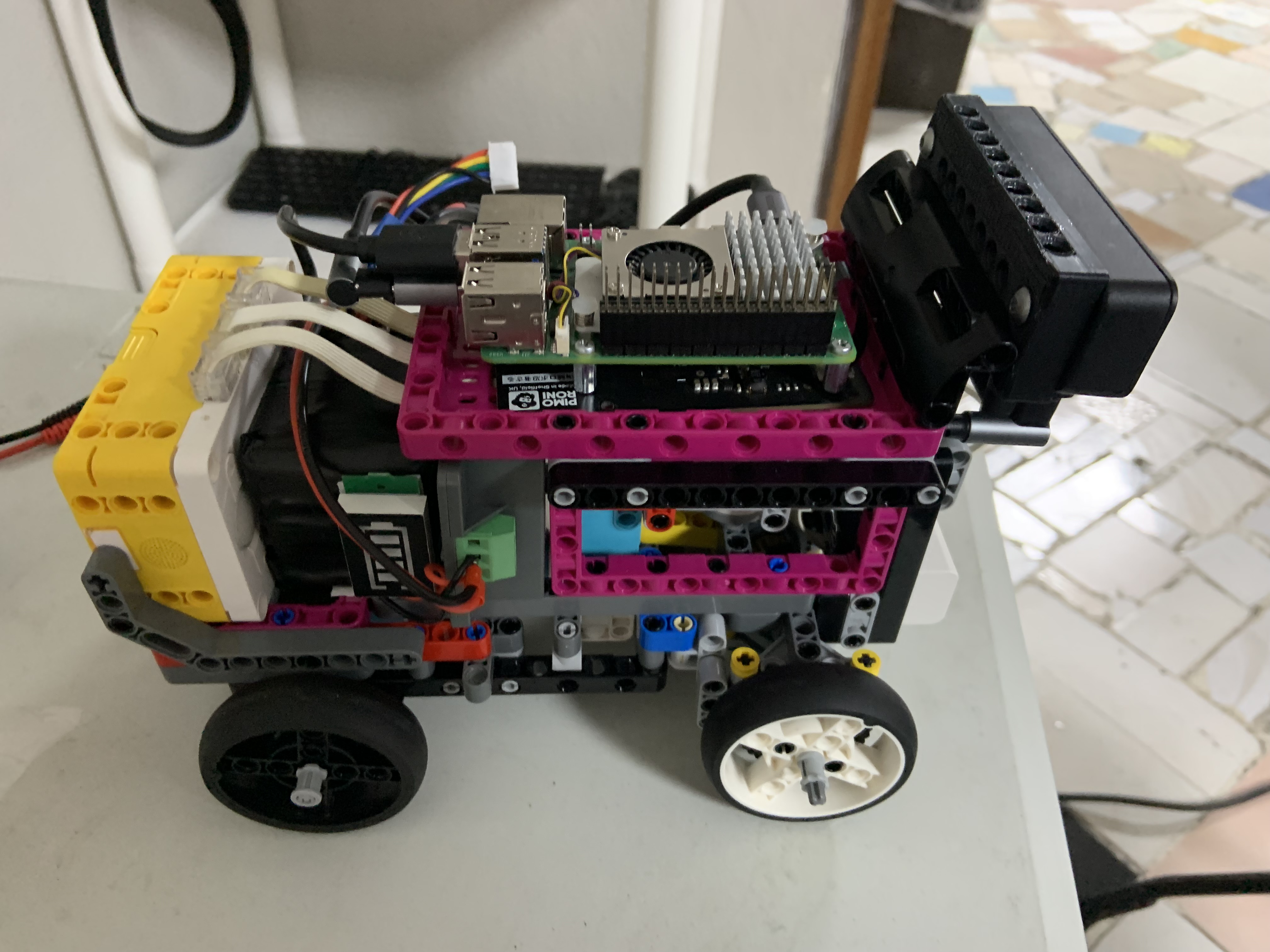
2025 season — two designs

v1 — Hybrid LEGO Technic chassis
Regional competition (Querétaro). Fast to iterate, but component placement was dictated by the Technic hole grid and the assembly had play at every beam connection.

v2 — Fully custom 3D-printed chassis
National competition, 2nd place nationally. Double-Ackermann steering, AWD, RPLidar S2L. Left us with three structural problems: barely under 1.5 kg, high centre of gravity, inconsistent steering.
2026 season — clean-sheet redesign, then four iterations

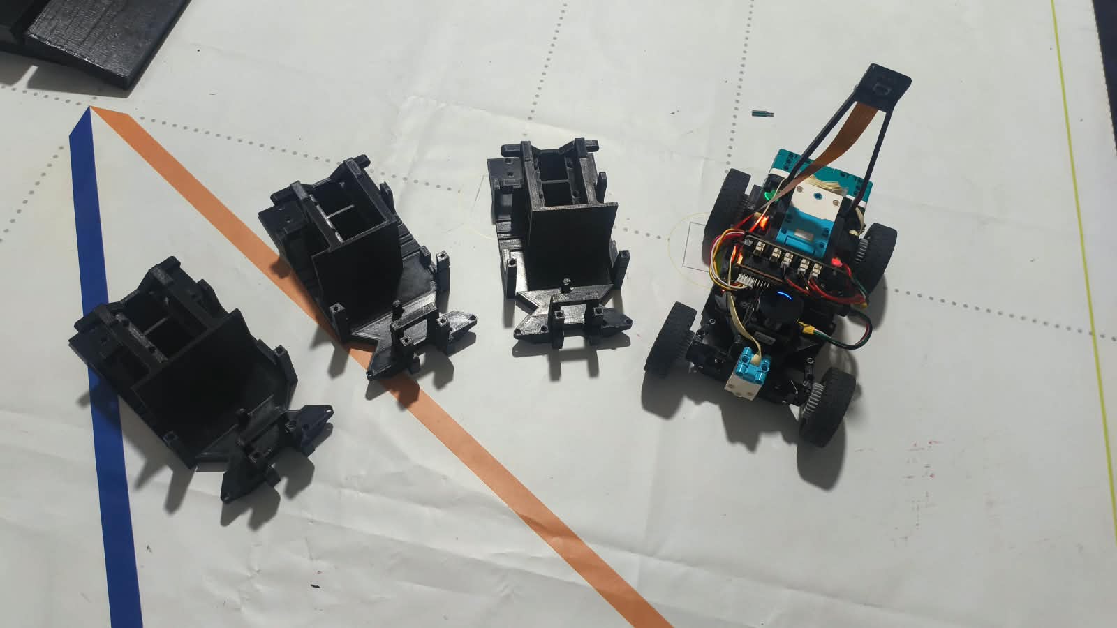
v3, v4, v5 (bare printed frames) and v6 (assembled, right)
The progression is visible in the frame itself: material removed, mounting features consolidated, and the central bay opened up to drop the electronics lower.

v6 (final) — "The Maker"
RWD, regular Ackermann, Oradar MS200k LiDAR, Raspberry Pi 5 + Hailo-10H. 240 × 160 × 250 mm, 1.006 kg.
### Key Challenges & Solutions * **The LiDAR could not see the walls.** After the compact chassis was finished the robot behaved as though blind. The dense repackaging had raised the LiDAR so its scanning plane passed *over* the 100 mm track walls, every wall reading was a miss, not a bad measurement. We revised the central CAD mount to bring the sensor down to ~60–80 mm while keeping the rear field of view clear. Sensor placement is now treated as a constraint set by the field, checked *before* a chassis is printed. * **Brownouts under hard acceleration.** The Pi 5 and Hailo accelerator caused abrupt shutdowns during acceleration, with the pack still charged. The traction motor's current spike was sagging the rail through the high internal resistance of generic 18650 cells. Fixed with Panasonic NCR18650B cells plus the X1203 board. The lesson: we had specified the pack by capacity (mAh), which is the wrong criterion for a load with sharp transients. * **Python could not keep up.** With a higher-rate camera and LiDAR attached, the 2025 Python control loop consumed data slower than the sensors produced it, so the robot acted on stale readings. We rewrote acquisition and control in C/C++, a rewrite rather than an optimisation, because the ceiling was the runtime itself, not any single slow function. The loop now runs at **> 50 Hz**. --- ## 5. Construction Guide Visit [Assembly instructions](other/Assembly_photos/Assembly_Process_EN.md) for all the details. ## 6. Bill of Materials (BOM) | Component | Quantity | Unit Cost (MXN) | Total per Component (MXN) | | --- | --- | --- | --- | | [LEGO SPIKE Prime Large Angular Motor (Part 45602)](https://store.edacom.mx/products/spike-motor-angular-grande?pr_prod_strat=e5_desc&pr_rec_id=72c621cae&pr_rec_pid=7107742367844&pr_ref_pid=7253040758884&pr_seq=uniform) | 1 | $1,737.85 | $1,737.85 | | [LEGO SPIKE Prime Small Angular Motor (Part 45607)](https://store.edacom.mx/products/spike-motor-angular-pequeno) | 1 | $1,643.96 | $1,643.96 | | [LEGO Technic Large Hub (Part 45601)](https://www.toytag.com/en-us/products/lego-technic-45601-large-hub-for-spike-prime) | 1 | $10,775.82 | $10,775.82 | | [4-Pack: LEGO Tires 62.4 x 20 S (32019) & Rims (86652)](https://www.amazon.com.mx/LEGO-Tire-86652-32019-75999/dp/B01CODUYCE) | 1 | $2,079.07 | $2,079.07 | | [Geekworm X1203 5.1V 5A UPS Shield for Raspberry Pi 5 Series](https://geekworm.com/products/x1203) | 1 | $760.05 | $760.05 | | [Raspberry Pi 5 (16GB RAM)](https://www.330ohms.com/shop/raspberry-pi-raspberry-pi-5-2/rp-01113-raspberry-pi-5-16gb-1501) | 1 | $7,329.99 | $7,329.99 | | [Raspberry Pi Camera Module 3 Wide](https://www.330ohms.com/shop/raspberry-pi-raspberry-pi-zero-9/rp-00874-raspberry-pi-camara-3-wide-1326) | 1 | $949.99 | $949.99 | | [Grove Relay Module](https://www.geekfactory.mx/producto/relevador-grove/) | 1 | $48.00 | $48.00 | | [Grove Red LED Button Module](https://www.330ohms.com/shop/sd-20069-boton-con-led-rojo-grove-361) | 1 | $16.19 | $16.19 | | [Raspberry Pi AI HAT+ 40 TOPS (Hailo-10H)](https://www.330ohms.com/shop/raspberrypi-ai-hat2-40tops-1612) | 1 | $5,002.00 | $5,002.00 | | [Orbbec Oradar MS200k LiDAR](https://tecnodrive.es/products/lidar-ms200k) | 1 | $1,796.21 | $1,796.21 | | [Panasonic NCR18650B 3400mAh 18650 Li-ion Battery](https://www.mercadolibre.com.mx/ncr18650b-bateria-panasonic-18650-3400mah/up/MLMU723197120#polycard_client=search-desktop&be_origin=backend&overlay_label=not_apply&search_layout=grid&position=10&type=product&tracking_id=464dd6eb-79c7-47da-8f85-c58e41ed7a4d&wid=MLM596134222&sid=search) | 4 | $219.90 | $879.60 | | **Total (MXN)** | | | **$33,018.73** | > **Disclaimer:** Conversion rates obtained from Google and applied when necessary: 1 United States Dollar equals 16.89 Mexican Peso (Sep 6, 8:28 PM UTC · From Morningstar); 1 Euro equals 19.62 Mexican Peso (Sep 6, 8:32 PM UTC). All prices were retrieved from the links on Sep 6, 2026. --- ### Conversion Notes * **LEGO Technic Large Hub (45601):** $638.00 USD × 16.89 MXN = **$10,775.82 MXN** * **Geekworm X1203 UPS Shield:** $45.00 USD × 16.89 MXN = **$760.05 MXN** * **Orbbec Oradar MS200k LiDAR:** €91,55 EUR × 19.62 MXN = **$1,796.21 MXN** * **Panasonic NCR18650B Batteries:** $219.90 MXN × 4 units = **$879.60 MXN** --- ## 7. Repository Structure ```text . ├── models/ # CAD designs and 3D vehicle models │ └── cad/ # Computer-Aided Design files │ ├── Final_assembly/ # Current vehicle chassis CAD assembly │ ├── Iterations/ # Prototype iterations and legacy CAD files │ └── Stl/ # STL CAD Files ├── other/ # Supporting materials and external software │ ├── additionalMedia/ # Extra media assets for documentation │ │ ├── Others/ # Miscellaneous diagrams and graphic assets │ │ └── Videos/ # Short testing clips and component videos │ ├── Assembly_photos/ # Pictures for construction guide │ ├── dataset/ # Computer vision dataset for model training │ │ ├── images/ # Raw/annotated training images │ │ └── labels/ # Bounding box labels (YOLO format) │ ├── datasheets/ # Hardware datasheets for sensors and motors │ ├── software_26topsRaspHAT/ # Raspberry Pi & Hailo AI HAT setup/tools │ ├── Training_model_and_results/ # Model training scripts and evaluation logs │ │ └── weights/ # Model weights (.pt, .onnx, .hef) │ └── WRO-2026-FE_GeneralRules.pdf # WRO official competition rules ├── schemes/ # Electrical documentation & schematics │ └── hardware/ # Circuit designs and wiring diagrams │ └── pcb/ # Custom PCB schematics and board layouts │ └── wiringSchematics.jpeg # System wiring diagram/schematics ├── src/ # Main C++ autonomous driving software │ ├── config/ # System YAML parameters and config files (Hailo) │ ├── cpp/ # Core driving, perception, and control logic │ ├── HailoModels/ # Pre-compiled models for Hailo AI accelerator │ ├── ondevice/ # Onboard sensor drivers and SDKs │ │ ├── oradar_sdk/ # ORadar LiDAR SDK │ │ └── rplidar_sdk/ # RPLiDAR SDK │ └── tools/ # Utility test scripts and helper binaries (Hailo) ├── t-photos/ # Team photos (members & coaches) ├── v-photos/ # Required 6-view vehicle photos │ └── Robot_More_Photos/ # High-resolution gallery & field testing shots ├── video/ # Open and Obstacle Challenges YouTube video links ├── .gitignore # .gitignore ├── Engineering_Journal_CSS_WRO2026.pdf # Engineering Journal PDF ├── LICENSE # MIT LICENSE file ├── SERVICES_README.md # Explanation for setting up daemon services └── README.md # Main project documentation ``` ## 8. Setup & Execution Instructions This repository builds **two separate programs**: `object_detection` (Obstacle Challenge, camera + Hailo-10H + LiDAR) and a second binary under `src/ondevice/` (Open Challenge, LiDAR + SPIKE hub only, no camera/Hailo). Steps 8.1–8.3 are shared setup; 8.4 and 8.5 cover each program's build/run. >*More detailed instructions in:*[`src\README.md`](src/README.md) ### 8.1 Prerequisites (OS & hardware stack) 1. **Flash the OS.** Raspberry Pi OS 64-bit (Bookworm or newer) on the Pi 5, via Raspberry Pi Imager. Enable SSH/serial as needed. 2. **Install the Hailo-10H stack** (required for the Obstacle Challenge only). Follow Hailo's Raspberry Pi setup for the AI HAT/M.2 Hailo-10H accelerator: install the `hailo-all` (or Hailo-10H specific) apt packages / PCIe driver + firmware + `HailoRT` runtime + `hailortcli`, then reboot and confirm the device is detected: ```bash hailortcli fw-control identify ``` The installed HailoRT version must match (or be compatible with) the Hailo Dataflow Compiler version used to produce the `.hef` files, for the Hailo-10H specifically, both must be **v5.x** (Hailo-8/8L use a different, incompatible v3.x/v4.x pairing). Mismatched versions are a common cause of a `.hef` that "compiles fine" but fails to load on the Pi. 3. **Install build dependencies:** ```bash sudo apt update sudo apt install -y build-essential cmake git libopencv-dev libgpiod-dev pkg-config ``` ### 8.2 Clone the repository ```bash git clone --recurse-submodules https://github.com/alex309-duarte/WRO_Future_Engineers_Queretaro_CSS.git # or, if already cloned: git submodule update --init --recursive ``` The `--recurse-submodules` step is required, `yaml-cpp` and `curl` under `src/cpp/external/` are vendored as submodules. ### 8.3 Wire up the hardware - **SPIKE Prime hub:** USB cable, appears as `/dev/ttyACM0` at 115200 baud. - **Orbbec Oradar MS200k LiDAR:** USB-serial, `/dev/ttyUSB0` at 230400 baud. - **GPIO** (BCM numbering): start button on GPIO4, status LED on GPIO3, SPIKE power relay on GPIO2. *To verify connection with SPIKE Prime HUB, run:* ```bash screen /dev/ttyACM0 115200 ``` ### 8.4 Build & run, Obstacle Challenge (`object_detection`) 1. **Place the model.** Put a compiled `.hef` (see §8.6 to produce your own) under `src/HailoModels/`, or let `resources_manager` resolve/download it per `src/config/resources_config.yaml`. 2. **Set the visualization config path.** `main()` falls back to a hardcoded path that won't exist on a fresh Pi, so export the real one first: ```bash export WRO_VISUALIZATION_CONFIG=/absolute/path/to/src/cpp/object_detection_original_h10/visualization_config.yaml ``` 3. **Build:** ```bash cd src/cpp/object_detection_original_h10/build/h10_original make ``` 4. **Run** (competition mode, no display): ```bash sudo ./object_detection --net /path/to/roboflow_yolov8n_wro_h10.hef --input rpi --no-display ``` **Run with display** (for debugging/calibration on-track): ```bash sudo ./object_detection --net /path/to/roboflow_yolov8n_wro_h10.hef --input rpi ``` ### 8.5 Build & run, Open Challenge (`src/ondevice/`) This binary is built via its own `Makefile` (not CMake) and must be built with the Oradar driver explicitly selected, plain `make` defaults to last year's RPLidar S2L driver, which this year's hardware doesn't use: ```bash cd src/ondevice make LIDAR=oradar make sudo ./my_lidar_app ``` ### 8.6 Calibration steps before first run - **Gyro:** zeroed automatically at the start of every run (`Reset gyro to 0°`), no manual calibration step needed here. - **LiDAR mount offset:** `ORADAR_ANGLE_OFFSET` is set to 270°, empirically confirmed for this chassis's LiDAR mounting orientation, only needs re-checking if the LiDAR's physical mounting angle changes. - **Ackermann steering angle:** fixed at 45.44° in hardware (§3.1), no software calibration needed. ### 8.7 (Optional) Producing your own `.hef` model from scratch Only needed if retraining the vision model rather than using the one already checked into `src/HailoModels/`. 1. **Get the labeled dataset**: ```bash git clone https://github.com/alex309-duarte/WRO_Future_Engineers_Queretaro_CSS.git ``` > Dataset in [`other\dataset`](other/dataset)\ > Training model and results in [`other\Training_model_and_results`](other/Training_model_and_results) 2. **Train the YOLOv8n model** via Google Colab, using [Luxonis's training notebook](https://colab.research.google.com/github/luxonis/depthai-ml-training/blob/master/colab-notebooks/YoloV8_training.ipynb). This project's model was trained with `model=yolov8n.pt`, `epochs=100`, `batch=16`, `imgsz=320`. 3. **Export to `.hef`**, on a laptop/desktop (not the Pi), the recommended one-command path via Ultralytics: ```bash pip install ultralytics pip install /path/to/hailo_dataflow_compiler---linux_x86_64.whl ``` ```python from ultralytics import YOLO model = YOLO("best.pt") model.export(format="hailo", name="hailo10h", imgsz=320, data="data.yaml") ``` Requires Hailo Dataflow Compiler **v5.x** (Hailo Developer Zone) for the Hailo-10H. 4. **Deploy:** copy the resulting `.hef` onto the Pi, into `src/HailoModels/`, and pass it via `--net` in §8.4 step 4. ## 9. Driving Videos [***Also on `video\video.md`***](video/video.md) ### Open Challenge *(Click on preview to visit YouTube Video)* [![Open Challenge](https://img.youtube.com/vi/gWYS8fVQXW0/maxresdefault.jpg)](https://www.youtube.com/shorts/gWYS8fVQXW0) ### Obstacle Challenge *(Click on preview to visit YouTube Video)* [![Obstacle Challenge](https://img.youtube.com/vi/b2bn9Eo9FxU/maxresdefault.jpg)](https://www.youtube.com/shorts/b2bn9Eo9FxU) --- ## 10. Resources ### About WRO - [WRO Official Site](https://wro-association.org/) - [Future Engineers Rules](other/WRO-2026-FE_GeneralRules.pdf) ### GitHub Repositories - [2026 Repository (WRO_Future_Engineers_Queretaro_CSS)](https://github.com/alex309-duarte/WRO_Future_Engineers_Queretaro_CSS) - [2025 Repository (WRO_2025_SSbots)](https://github.com/JRavenelco/WRO_2025_SSbots) ### Datasheets - [Orbbec Oradar MS200k LiDAR](other/datasheets/MS200k-dToF-2D-LiDARSR-User-Manual-A2-1.pdf) - [Raspberry Pi 5 (16GB RAM)](other/datasheets/RP-008348-DS-6-raspberry-pi-5-product-brief.pdf) - [Raspberry Pi AI HAT+ 40 TOPS (Hailo-10H)](other/datasheets/RP-009655-MM-6-raspberry-pi-ai-hat-plus-2-product-brief.pdf) - [Geekworm X1203 5.1V 5A UPS Shield for Raspberry Pi 5 Series](https://wiki.geekworm.com/X1203) - [LEGO SPIKE Prime Large Angular Motor (Part 45602)](other/datasheets/techspecs_techniclargeangularmotor-1b79e2f4fbb292aaf40c97fec0c31fff.pdf) - [LEGO SPIKE Prime Small Angular Motor (Part 45607)](other/datasheets/LE_SPIKE_Essential_Tech_fact_sheet_Small_Angular_Motor_45607_2HY21_Digital.pdf) - [LEGO Technic Large Hub (Part 45601)](other/datasheets/techspecs_techniclargehub.pdf) --- ## 11. License Released under the [MIT License](LICENSE). ```text MIT License Copyright (c) 2026 CSS (Christian Gael Centeno Velez, Sebastián Esquivel Mondragón) Permission is hereby granted, free of charge, to any person obtaining a copy of this software and associated documentation files (the "Software"), to deal in the Software without restriction, including without limitation the rights to use, copy, modify, merge, publish, distribute, sublicense, and/or sell copies of the Software, and to permit persons to whom the Software is furnished to do so, subject to the following conditions: The above copyright notice and this permission notice shall be included in all copies or substantial portions of the Software. THE SOFTWARE IS PROVIDED "AS IS", WITHOUT WARRANTY OF ANY KIND, EXPRESS OR IMPLIED, INCLUDING BUT NOT LIMITED TO THE WARRANTIES OF MERCHANTABILITY, FITNESS FOR A PARTICULAR PURPOSE AND NONINFRINGEMENT. IN NO EVENT SHALL THE AUTHORS OR COPYRIGHT HOLDERS BE LIABLE FOR ANY CLAIM, DAMAGES OR OTHER LIABILITY, WHETHER IN AN ACTION OF CONTRACT, TORT OR OTHERWISE, ARISING FROM, OUT OF OR IN CONNECTION WITH THE SOFTWARE OR THE USE OR OTHER DEALINGS IN THE SOFTWARE. ``` --- > *Document maintained by CSS | Last updated: September 2026*