# 🚀 WRO 2025 Future Engineers – ANTi
 [](https://www.instagram.com/anti.wro/)
[](https://www.youtube.com/@solipsy.)
---
## 🏆 **TURKISH NATIONAL CHAMPION – READY FOR SINGAPORE FINALS**
Welcome to the GitHub repository of **Team ANTi**, competing in the **World Robot Olympiad™ (WRO®) Future Engineers 2025** category. Our team is made up of Turkish students who have designed a compact, innovative, and autonomous self-driving vehicle to tackle the dynamic challenges of the WRO 2025 competition. Our team name, **ANTi**, reflects our philosophy: like an **ANT**, our robot is exceptionally small yet highly capable, pushing the boundaries of minimalism in design. The "**ANT**i" signifies our competitive spirit, standing "versus the world" in pursuit of engineering excellence.
Our mission was to create the smallest possible robot for the WRO 2025 challenge, leveraging our expertise in electrical, mechanical, and software engineering to test the limits of the 3 m x 3 m game field. After winning the Turkish National Final, we rebuilt, re-tuned, and re-documented every subsystem for the International Final in Singapore on 26–28 Nov 2025.
Current best times on the 3 m x 3 m field:
- **Open Challenge**: 16 seconds (full score)
- **Obstacle Challenge**: 35 seconds (full score)
Complete performance demonstrations available in our [video documentation](video/README.md).
[](https://www.instagram.com/anti.wro/)
[](https://www.youtube.com/@solipsy.)
---
## 🏆 **TURKISH NATIONAL CHAMPION – READY FOR SINGAPORE FINALS**
Welcome to the GitHub repository of **Team ANTi**, competing in the **World Robot Olympiad™ (WRO®) Future Engineers 2025** category. Our team is made up of Turkish students who have designed a compact, innovative, and autonomous self-driving vehicle to tackle the dynamic challenges of the WRO 2025 competition. Our team name, **ANTi**, reflects our philosophy: like an **ANT**, our robot is exceptionally small yet highly capable, pushing the boundaries of minimalism in design. The "**ANT**i" signifies our competitive spirit, standing "versus the world" in pursuit of engineering excellence.
Our mission was to create the smallest possible robot for the WRO 2025 challenge, leveraging our expertise in electrical, mechanical, and software engineering to test the limits of the 3 m x 3 m game field. After winning the Turkish National Final, we rebuilt, re-tuned, and re-documented every subsystem for the International Final in Singapore on 26–28 Nov 2025.
Current best times on the 3 m x 3 m field:
- **Open Challenge**: 16 seconds (full score)
- **Obstacle Challenge**: 35 seconds (full score)
Complete performance demonstrations available in our [video documentation](video/README.md).
 The car keeps its title of **World's Smallest Self Driving Autonomous Vehicle** (about 1/76 scale, **69mm (L) x 53mm (W) x 57mm (H)**) while now carrying more intelligence and sensors than ever before. We challenged ourselves beyond the traditional competition rules by pursuing minimal size alongside advanced engineering functionality to further develop our **engineering knowledge**.
Guided by our vision to ***"never stop developing unless we stop learning,"*** we have created a vehicle that demonstrates how constraints can drive creativity and technical excellence in autonomous systems design. This documentation was last updated on **Sunday, Nov 09 2025, at 09:24 PM +03**
---
## 📚 **Table of Contents**
- [📂 Complete Documentation Structure](#complete-documentation-structure)
- [👥 The Team](#the-team)
- [🎯 Challenge Overview](#challenge-overview)
- [🤖 Our Robot](#our-robot)
- [🔧 Electronic Systems](#electronic-systems)
- [⚙ Mechanical Systems](#mechanical-systems)
- [💻 Software Architecture](#software-architecture)
- [📹 Performance Videos](#performance-videos)
- [🌐 GitHub Utilization & Development](#github-utilization--development)
- [📜 License & Replication](#license--replication)
---
## 📂 **Complete Documentation Structure**
The car keeps its title of **World's Smallest Self Driving Autonomous Vehicle** (about 1/76 scale, **69mm (L) x 53mm (W) x 57mm (H)**) while now carrying more intelligence and sensors than ever before. We challenged ourselves beyond the traditional competition rules by pursuing minimal size alongside advanced engineering functionality to further develop our **engineering knowledge**.
Guided by our vision to ***"never stop developing unless we stop learning,"*** we have created a vehicle that demonstrates how constraints can drive creativity and technical excellence in autonomous systems design. This documentation was last updated on **Sunday, Nov 09 2025, at 09:24 PM +03**
---
## 📚 **Table of Contents**
- [📂 Complete Documentation Structure](#complete-documentation-structure)
- [👥 The Team](#the-team)
- [🎯 Challenge Overview](#challenge-overview)
- [🤖 Our Robot](#our-robot)
- [🔧 Electronic Systems](#electronic-systems)
- [⚙ Mechanical Systems](#mechanical-systems)
- [💻 Software Architecture](#software-architecture)
- [📹 Performance Videos](#performance-videos)
- [🌐 GitHub Utilization & Development](#github-utilization--development)
- [📜 License & Replication](#license--replication)
---
## 📂 **Complete Documentation Structure**
## 🔍 **DETAILED TECHNICAL DOCUMENTATION AVAILABLE**
### **Each folder contains comprehensive README documentation with specialized technical content**
| 📁 Folder | 🎯 Technical Content | 📖 Detailed Documentation |
|-----------|----------------------|---------------------------|
| **🧮 MATLAB** | **Vision System Calibration**
• LAB colorspace analysis
• Threshold optimization
• Lighting condition testing | [🔗 Explore MATLAB Documentation](matlab/README.md) |
| **⚙ Models** | **Mechanical Engineering**
• 3D CAD designs
• Assembly instructions
• Gear system calculations | [🔗 Explore 3D Models & Assembly Documentation](models/README.md) |
| **🔌 Schemes** | **Electrical Systems**
• Wiring diagrams
• Power management
• Component schematics & datasheets | [🔗 Explore Schematics & Wiring Documentation](schemes/README.md) |
| **💾 Source Code** | **Software Algorithms**
• Navigation logic
• Sensor fusion
• Control systems | [🔗 Explore Software & Algorithms Documentation](src/README.md) |
| **👥 Team Photos** | **Team Documentation**
• Member profiles
• Development journey
• Competition preparation | [🔗 Explore Team Photos Documentation](t-photos/README.md) |
| **🚗 Vehicle Photos** | **Vehicle Documentation**
• Multi-angle views
• Component labeling
• System integration | [🔗 Explore Vehicle Photos Documentation](v-photos/README.md) |
| **🎥 Videos** | **Performance Validation**
• Challenge demonstrations
• Engineering tests
• System validation | [🔗 Explore Performance Videos Documentation](video/README.md) |
| **📚 Other Resources** | **Technical References**
• Component images
• Development resources
• Additional documentation | [🔗 Explore Additional Resources Documentation](other/README.md) |
---
## 👥 **The Team**
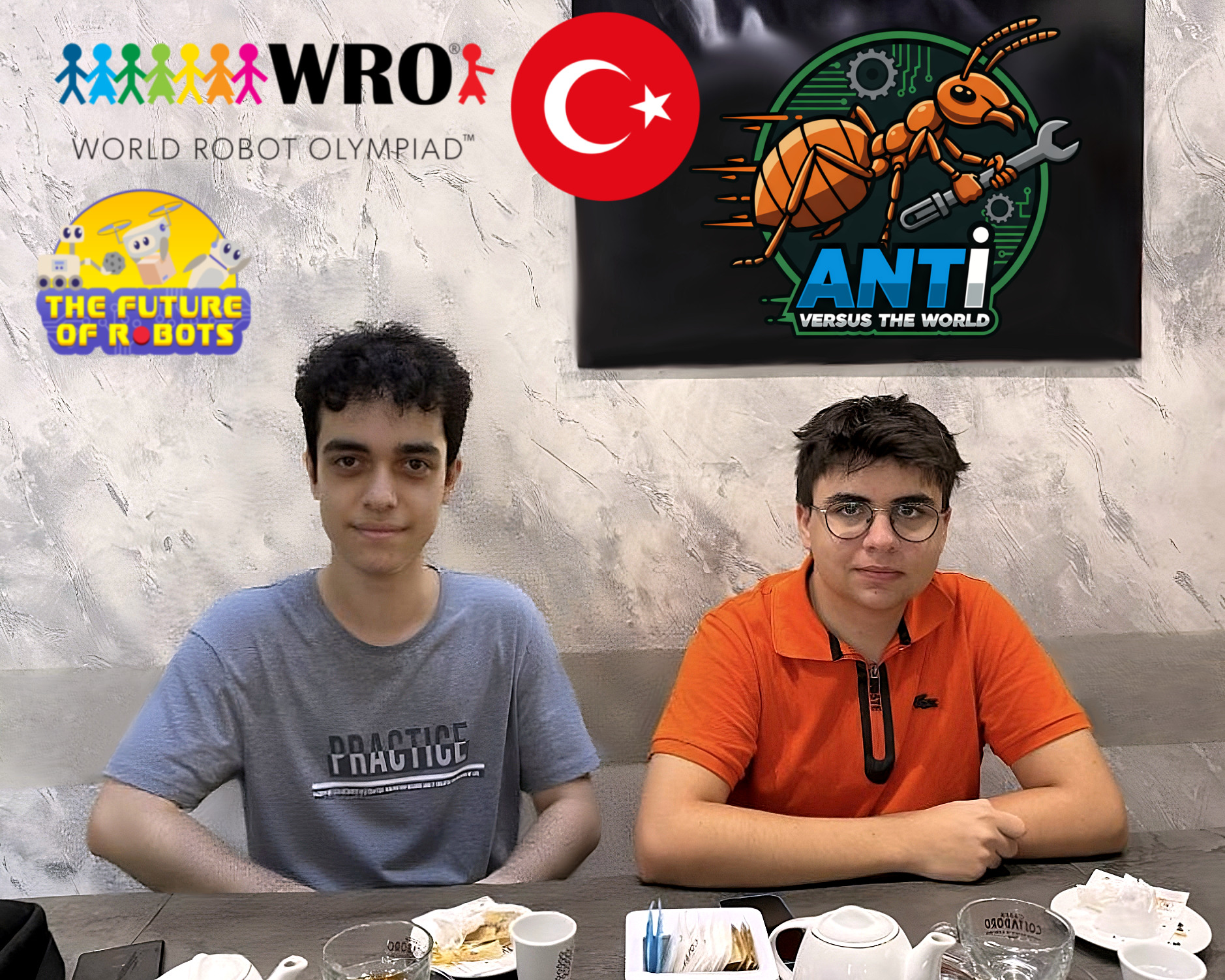
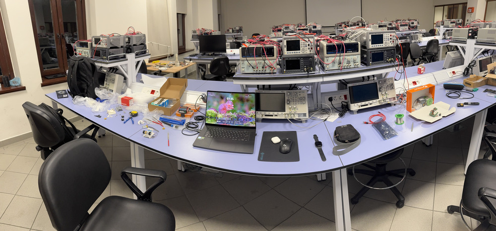
Team ANTi includes passionate students from Türkiye, guided by a coach. This is our **first year** competing in the WRO Future Engineers category, and each member brings unique skills to the project, from electronics to computer vision.
### **Members**
- **Atakan Ersoy** (Team Leader)
*Role*: Electronics, Mechanical Design, Software, Strategy Integration
*Background*: Sophomore, Electrical and Electronics Engineering, Koç University (2025)
*Contact*: [atakan@atakanersoy.com](mailto:atakan@atakanersoy.com), [aersoy24@ku.edu.tr](mailto:aersoy24@ku.edu.tr)
*Born*: 2006, Türkiye
- **Ege Özokan**
*Role*: Computer Vision Research, Strategy
*Background*: Freshman, Computer Engineering, Politecnico di Torino (2025)
*Born*: 2006, Türkiye
### **Coach**
- **Ali Aral Eren**
*Role*: Team Coach, Connector
*Background*: Alumni, Electrical and Electronics Engineering, Koç University (2025)
*Born*: 2003, Türkiye
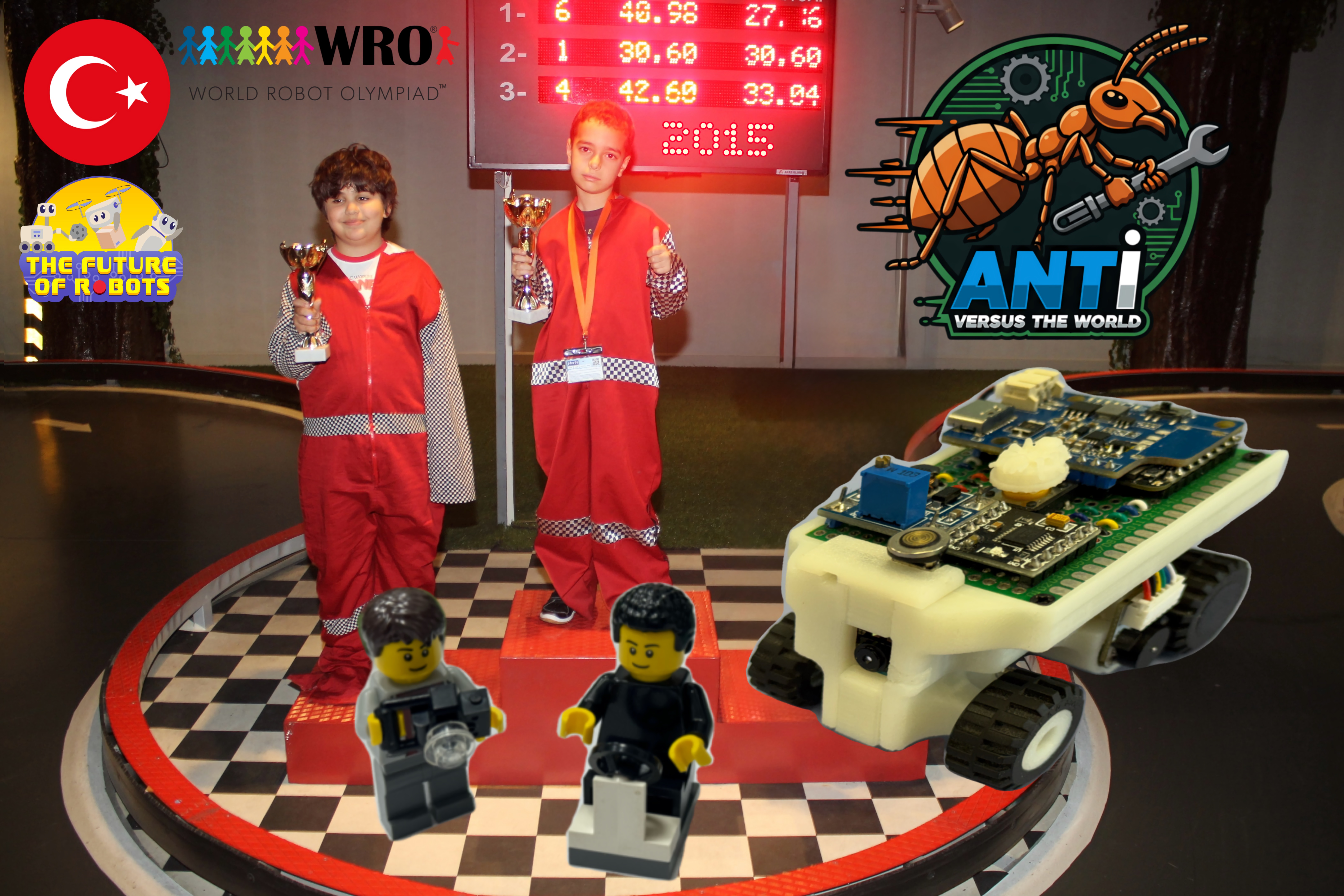
> 💡 *Fun Fact*: The fun team photo (`team_fun.jpg`) is our childhood photo from 2015, when we were 9 years old, standing on a go-kart race podium!
### **Team Journey Moments**
Throughout our development process from initial concept to competition readiness, we captured key moments demonstrating our collaborative spirit and technical dedication. These images showcase our brainstorming sessions, technical adjustments, and competition preparation.
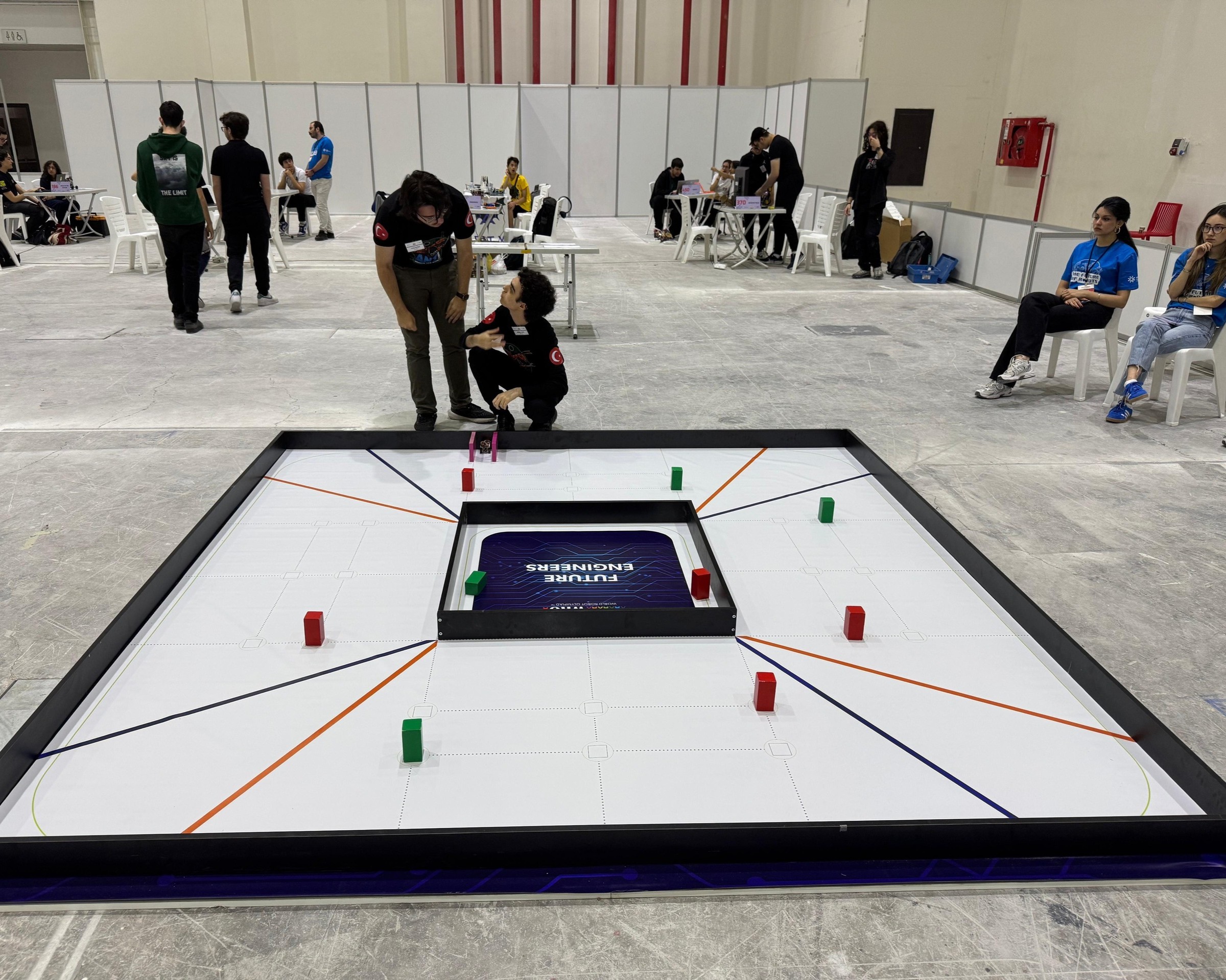
Team members collaborating during national final competition - discussing strategy while testing the vehicle on the field and preparing to activate it.
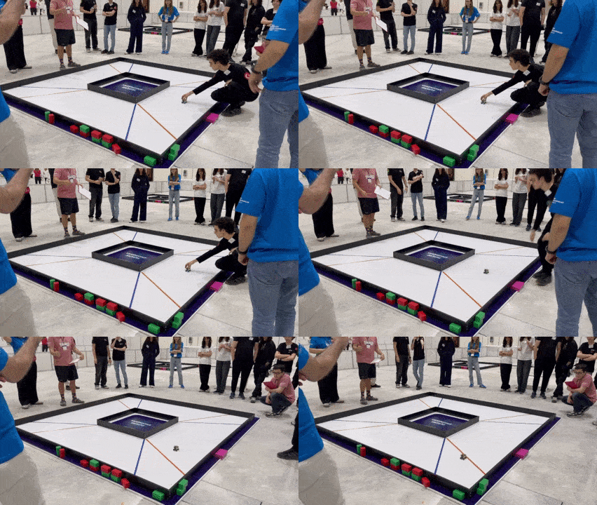
Dynamic view of official competition start during national final - team member pressing start button with excitement as vehicle begins its run.
---
## 🎯 **Challenge Overview**
## 🏁 **WRO 2025 Future Engineers Challenges**
### **Two distinct autonomous navigation challenges testing vehicle intelligence and precision**
### **🚀 Open Challenge**
**Objective**: Complete three autonomous laps on dynamically configured tracks
| Aspect | Challenge | Our Solution |
|--------|-----------|--------------|
| **Track Variability** | Random internal wall placements | Adaptive path planning algorithms |
| **Navigation** | Unknown track layouts each round | Robust wall-following with corner detection |
| **Performance** | Consistent lap times across variations | Optimized PID control and sensor fusion |
| **Precision** | Maintain course in narrow lanes | High-accuracy steering and speed control |
### **🚧 Obstacle Challenge**
**Objective**: Navigate three laps with traffic sign compliance and precision parking
| Challenge Element | Requirement | Our Implementation |
|-------------------|-------------|-------------------|
| **Traffic Signs** | Red → Right bias
Green → Left bias | Real-time color detection with LAB colorspace |
| **Obstacle Avoidance** | Dynamic path adjustment | Smooth following at consistent distances |
| **Parking Maneuver** | Parallel parking after lap completion | Multi-stage parking with sensor validation |
| **Navigation** | Shortest path optimization | Efficient routing around obstacle combinations |
### **📁 Documentation Evaluation Framework**
## 📊 **WRO 2025 Engineering Documentation Scoring (30 points total)**
| Scoring Area | Maximum Points | Our Documentation Coverage |
|--------------|----------------|---------------------------|
| **1. Mobility Management** | 4 points | Complete mechanical design, motor selection, steering system, assembly instructions |
| **2. Power & Sense Management** | 4 points | Power systems, sensor integration, wiring diagrams, component specifications |
| **3. Obstacle Management** | 4 points | Navigation algorithms, parking strategies, source code with detailed comments |
| **4. Pictures – Team and Vehicle** | 4 points | Multi-angle vehicle photos, team photos, component labeling |
| **5. Performance Videos** | 4 points | Complete challenge demonstrations with commentary and analysis |
| **6. GitHub Utilization** | 4 points | Version control, structured documentation, regular commits |
| **7. Engineering Factor** | 4 points | Custom design and manufacturing throughout the vehicle |
| **8. Overall Judge Impression** | 2 points | Clear communication enabling easy replication |
| **Total Documentation Score** | **30 points** | **(≈25% of total competition score)** |
### **Key Evaluation Areas**
- **Performance and adaptability** in randomized track conditions
- **Precision in maneuvers**, especially parallel parking execution
- **Comprehensive public engineering documentation** on GitHub with complete transparency
- **Custom design innovation** and manufacturing process documentation
- **Professional presentation** enabling effortless replication by other teams
**Scoring Philosophy**: Documentation is evaluated based on completeness, structure, and ease of replication - not comparison between teams. Each scoring area uses a 0-4 point scale where "Exceeds Expectations" requires not only enabling exact duplication but also providing improvement suggestions.
### **🎓 Educational Objectives**
- **Advanced Computer Vision**: Real-world implementation of color space theory
- **Sensor Fusion**: Integrating multiple data sources for robust navigation
- **Control Systems**: Precision steering and speed control algorithms
- **Engineering Documentation**: Professional technical communication
- **Problem Solving**: Systematic approach to technical challenges
---
## 🤖 **Our Robot**
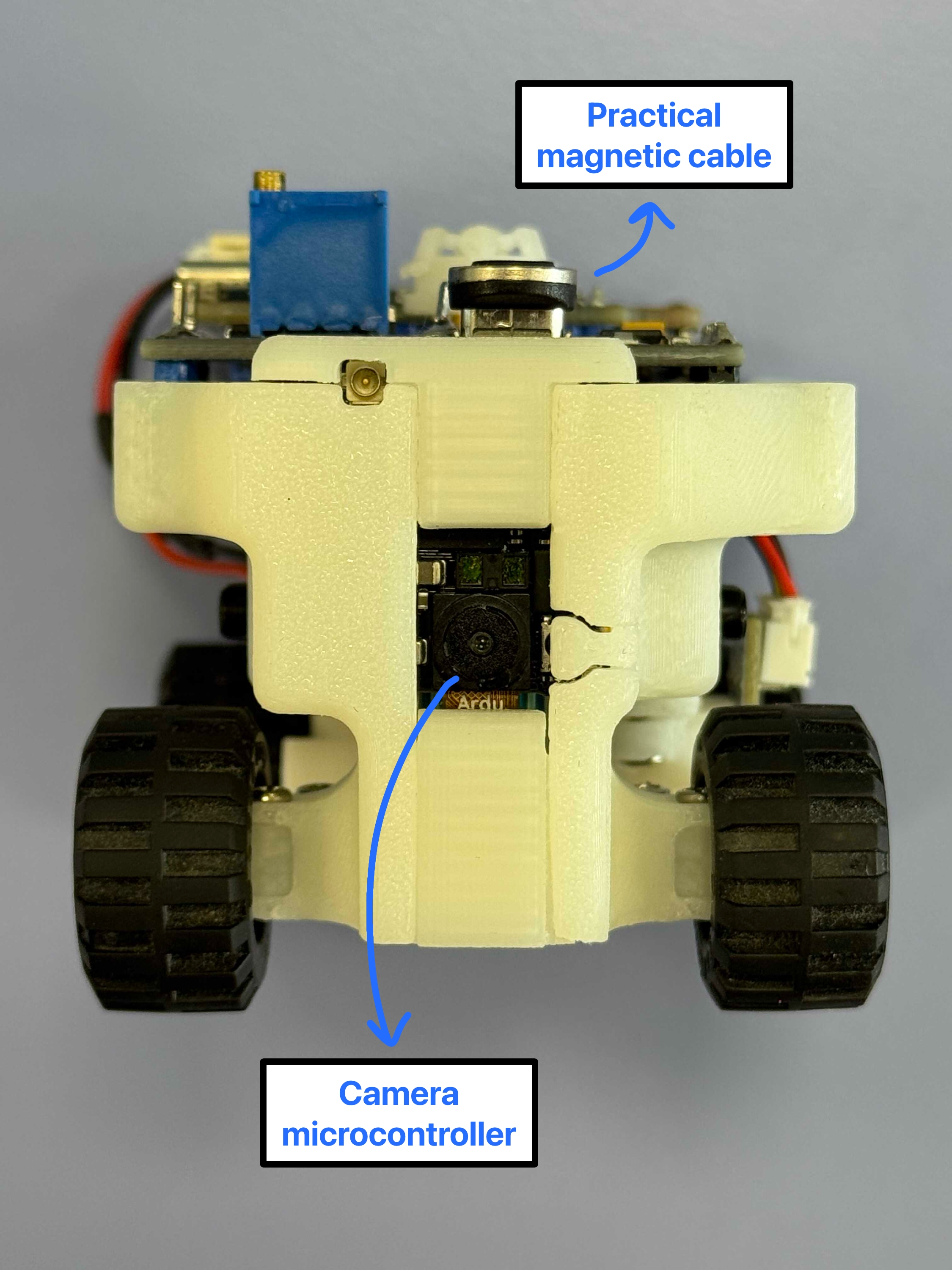
Our platform represents a breakthrough in compact autonomous vehicle design, achieving unprecedented miniaturization without compromising capability. The complete system integrates custom mechanical design with sophisticated electronic systems and advanced software algorithms.
**Core Processing Architecture**:
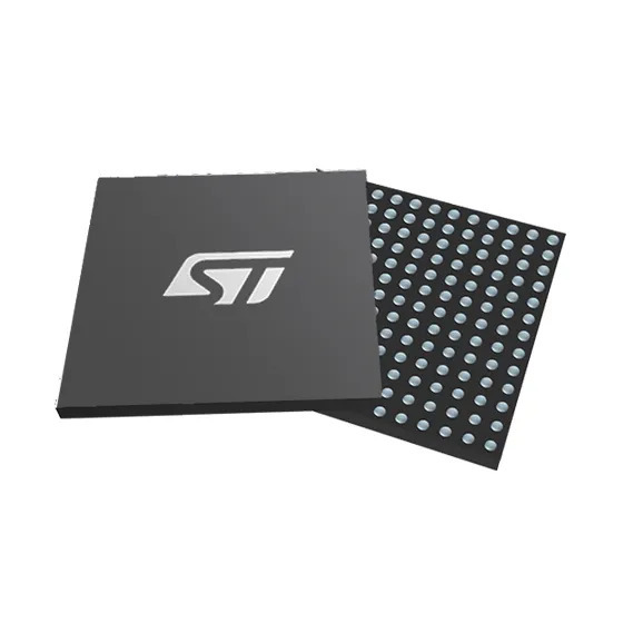
- **Primary Vision Processor**: STM32H747 dual-core microcontroller dedicated to real-time image processing
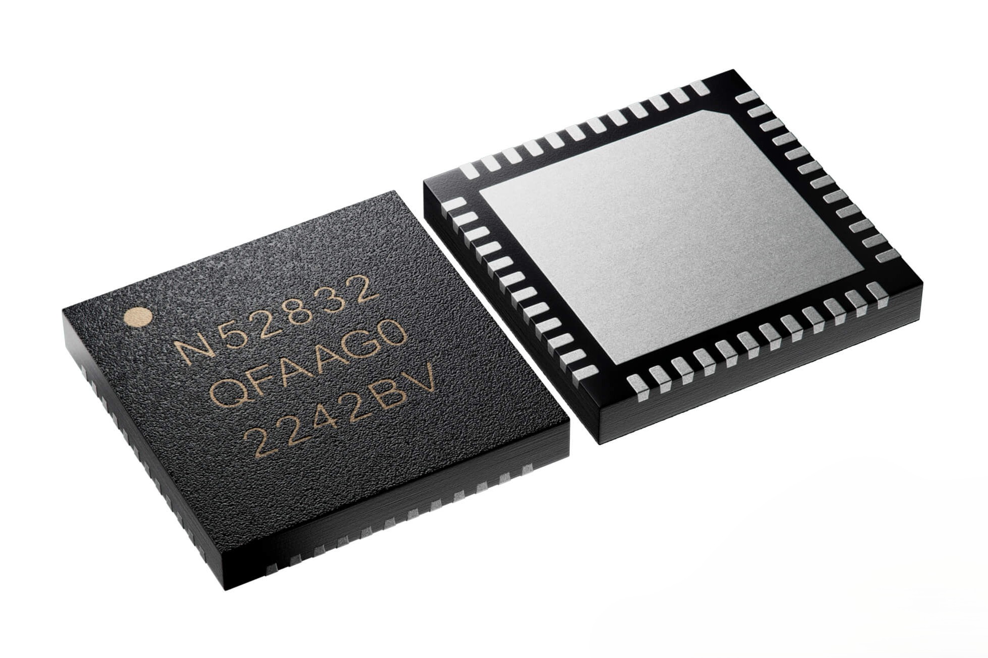
- **Secondary Sensor Processor**: nRF52832 microcontroller handling multi-sensor data fusion
- **Distributed Processing**: Optimized task allocation between vision and control subsystems
**Perception System**:
- **Front-Facing Detection**: VL53L1X Time-of-Flight sensor for general obstacle awareness
- **Side-Mounted Precision Sensors**: Dual VL53L3CX ToF sensors with custom optics for parking detection
- **Visual Navigation**: GC2145 2MP camera with optimized field of view for track following
**Propulsion and Control**:
- **Drive System**: 1500 RPM N20 motor with integrated encoder feedback
- **Steering Mechanism**: Custom Ackermann geometry with submicro servo actuation
- **Power Management**: Integrated LiPo system with comprehensive power distribution
Complete vehicle documentation with detailed component identification available in [vehicle photos](v-photos/README.md).
### Potential Future Improvements (Overall Vehicle)
- Reduce size even further to ≈ 60 × 45 × 50 mm by switching to smaller LiPo (3.7 V), a coreless motor + micro gearbox and smaller mechanic differential style.
- Implement four-wheel steering or active rear-axle 4 wheel drive to control for tighter turning radius on narrow lanes.
- Add a very small extra second camera facing backwards for reverse parking or emergency obstacle detection.
---
## 🔧 **Electronic Systems**
Our electronic architecture emphasizes modularity, reliability, and hands-on engineering through custom manufacturing approaches.
### **Component Integration Strategy**
| Component | Image | Quantity | Function | Key Specifications |
|-----------|-------|----------|----------|-------------------|
| **STM32H747** |
| 1 | Vision Processing | Dual-core Cortex-M7/M4, Camera Interface |
| **nRF52832** |
| 1 | Sensor Fusion | Multi-protocol wireless capable MCU |
| **GC2145 Camera** |
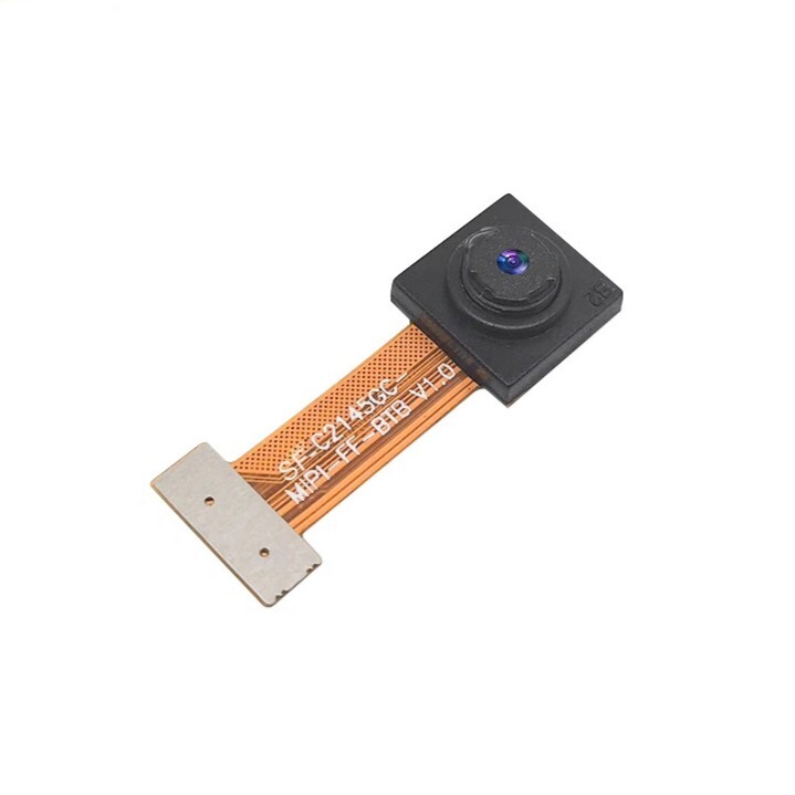
| 1 | Visual Navigation | 2MP resolution, 80° FOV, DCMI interface |
| **VL53L3CX ToF** |
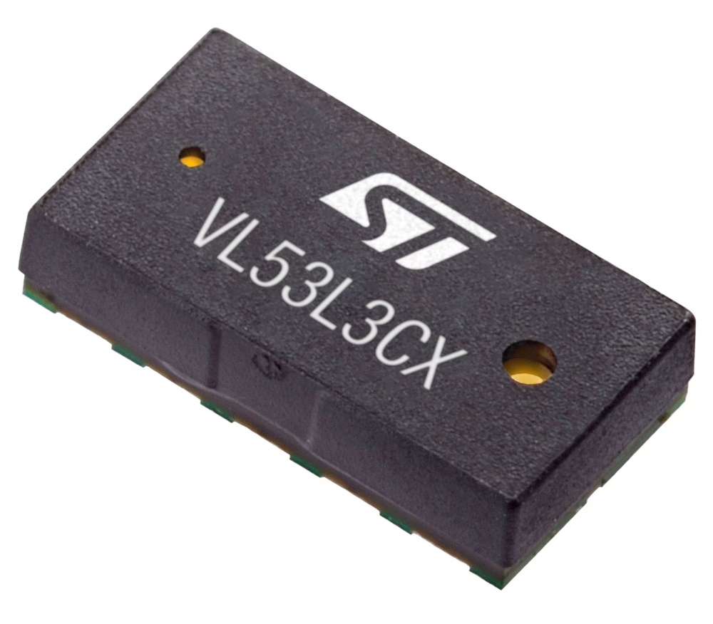
| 2 | Side Detection | 700cm range, window lens optics |
| **VL53L1X ToF** |
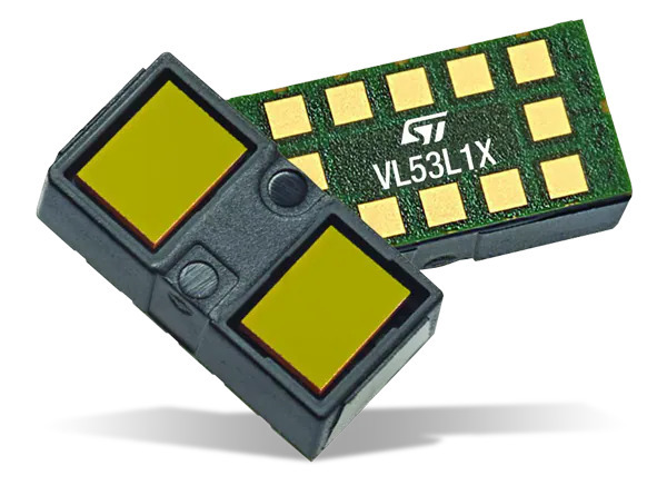
| 1 | Front Detection | 400cm range, programmable FoV |
| **LSM6DSOX IMU** |
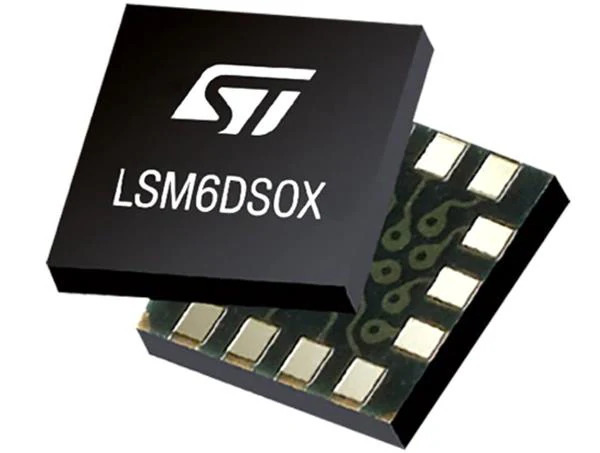
| 1 | Motion Tracking | 6-axis inertial measurement |
| **DRV8833 Driver** |
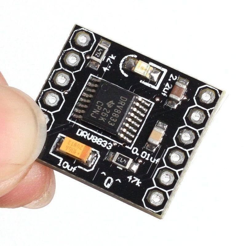
| 1 | Motor Control | Dual H-bridge, PWM control |
| **BOB-12009** |
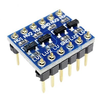
| 1 | Level Shifting | Bidirectional 3.3V-5V conversion |
| **SX1308 Booster** |
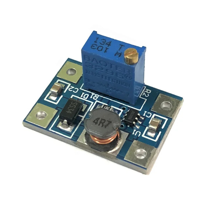
| 1 | Power Regulation | 2A step-up voltage conversion |
| **Feetech FS0307** |
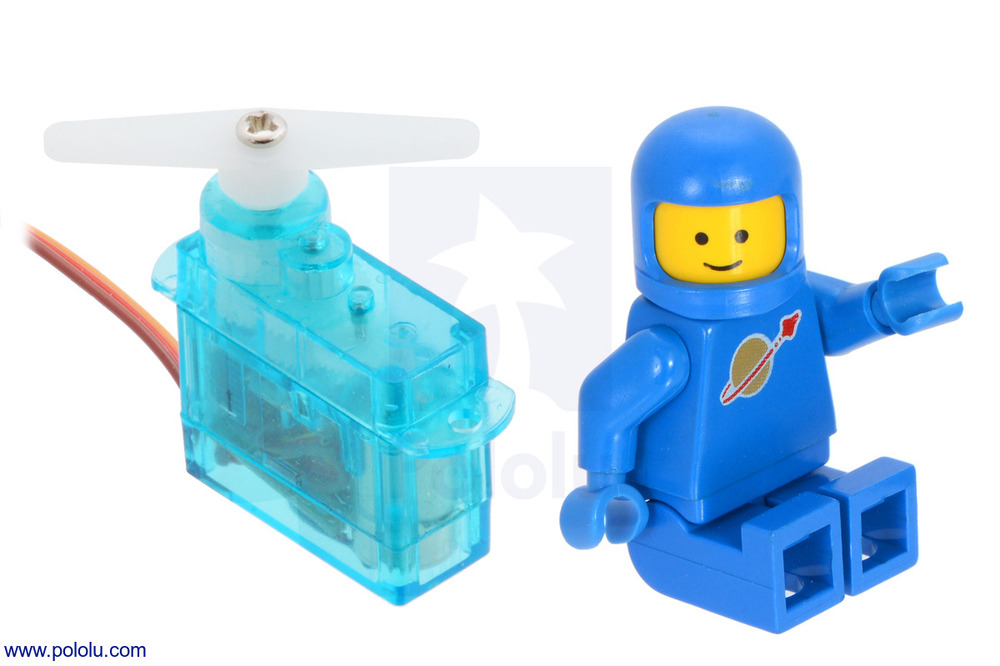
| 1 | Steering Actuation | Submicro form factor, precision control |
| **1500 RPM N20** |
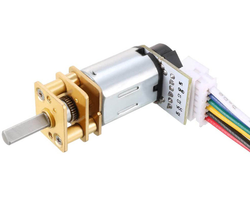
| 1 | Propulsion | Brushed DC with Hall effect encoder |
| **PX103035 Battery** |
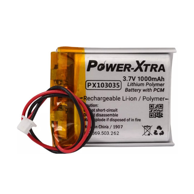
| 1 | Power Source | 1000mAh LiPo with protection circuit |
| **LiPo Rider Plus** |
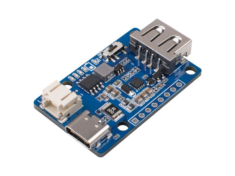
| 1 | Power Management | USB-C charging, multi-rail output |
| **KLS7-TS1204** |
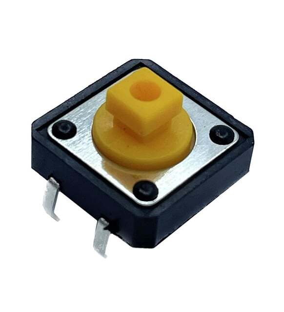
| 1 | User Interface | Tactile switch for system control |
| **LEGO 87697** |
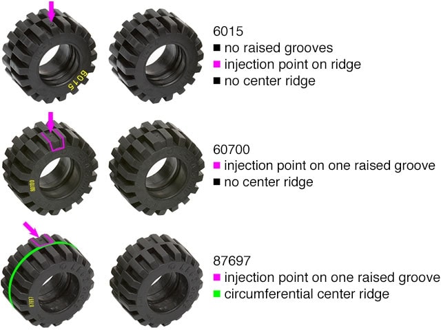
| 4 | Traction System | 21mm diameter, optimized tread pattern |
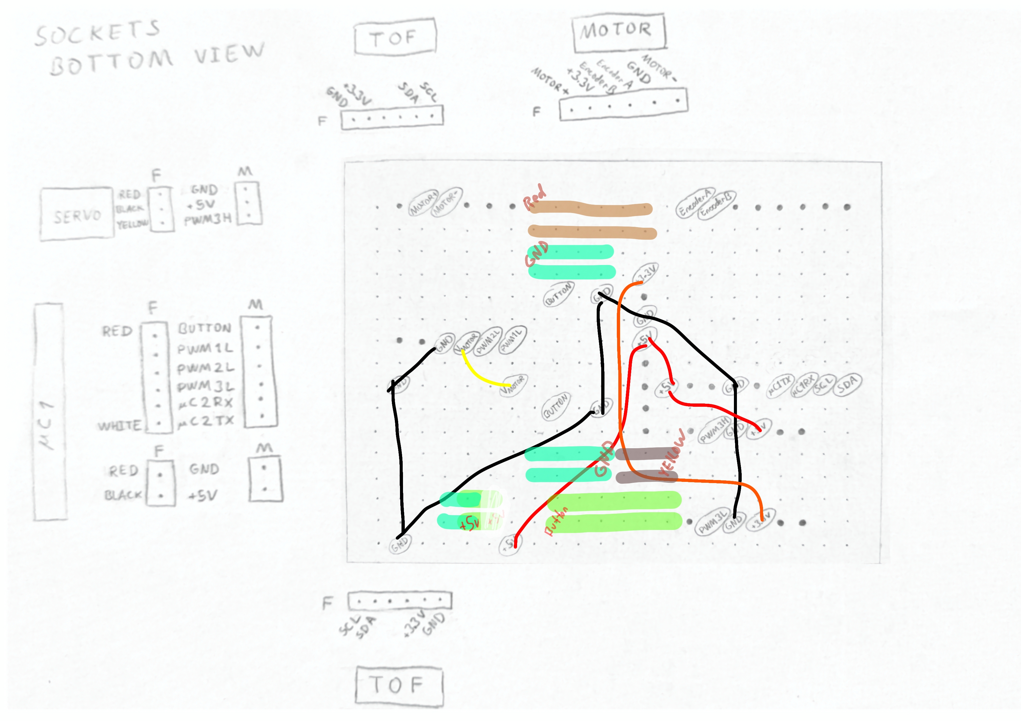
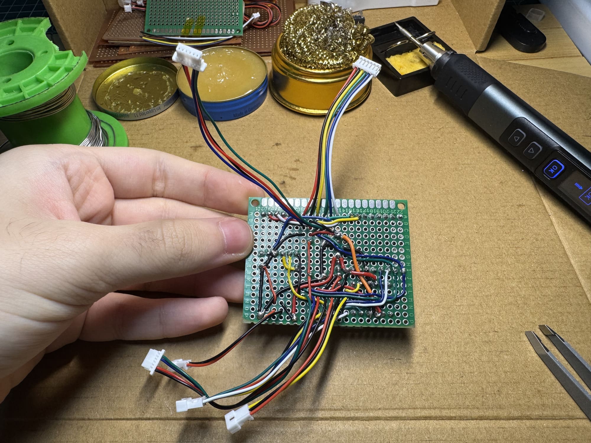
1) Complete hand-drawn and digitally traced professional wiring schematic showing all electrical connections (view full resolution) • 2) Physical implementation demonstrating socket-based construction of the schematic
### **Individual Component Schematics**
| Component Schematic | Description | Full Documentation |
|---------------------|-------------|-------------------|
|
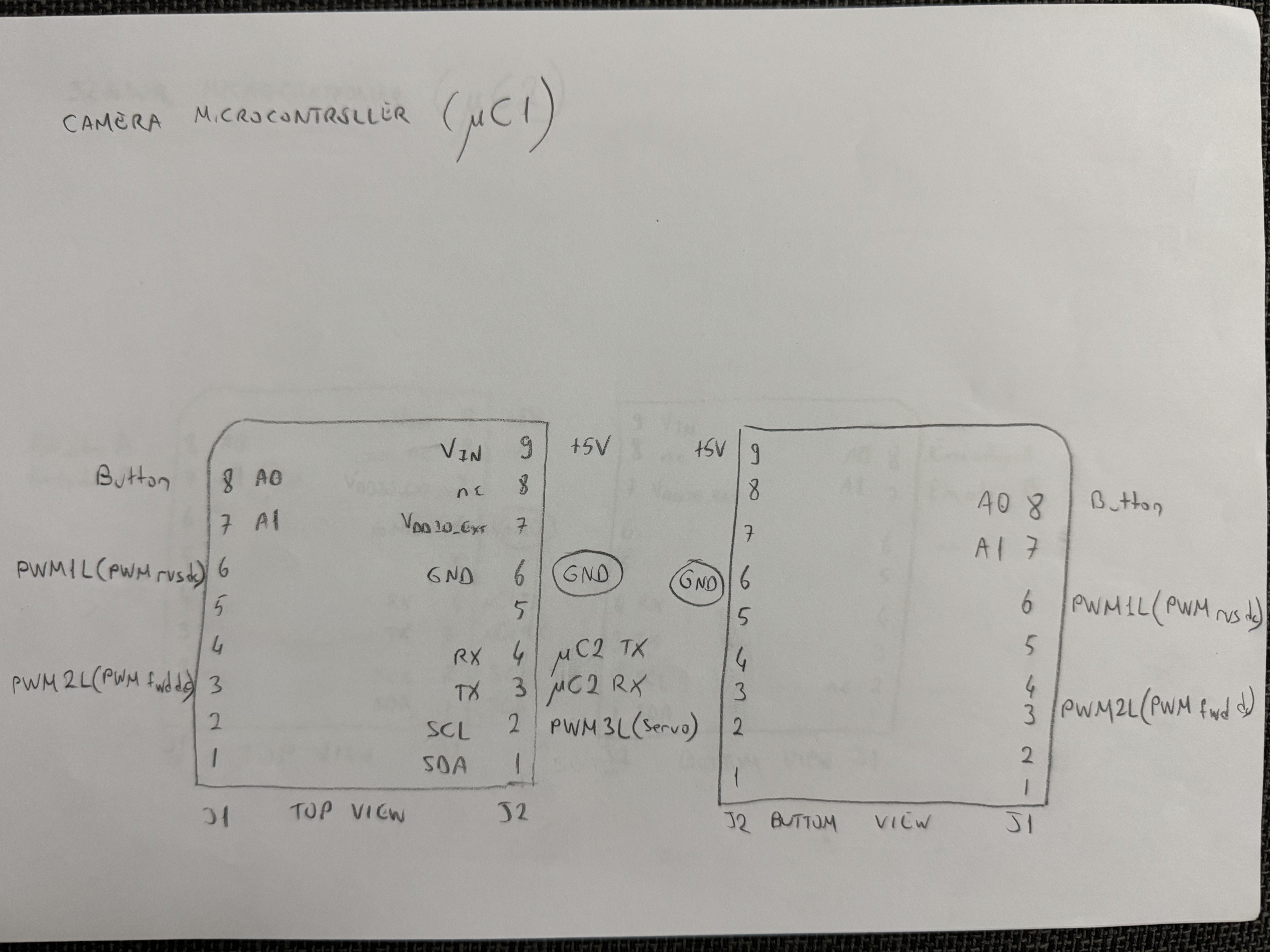
| **STM32H747 Camera Controller**
Camera interface and peripheral connections | [View Details](schemes/README.md#microcontroller-systems) |
|
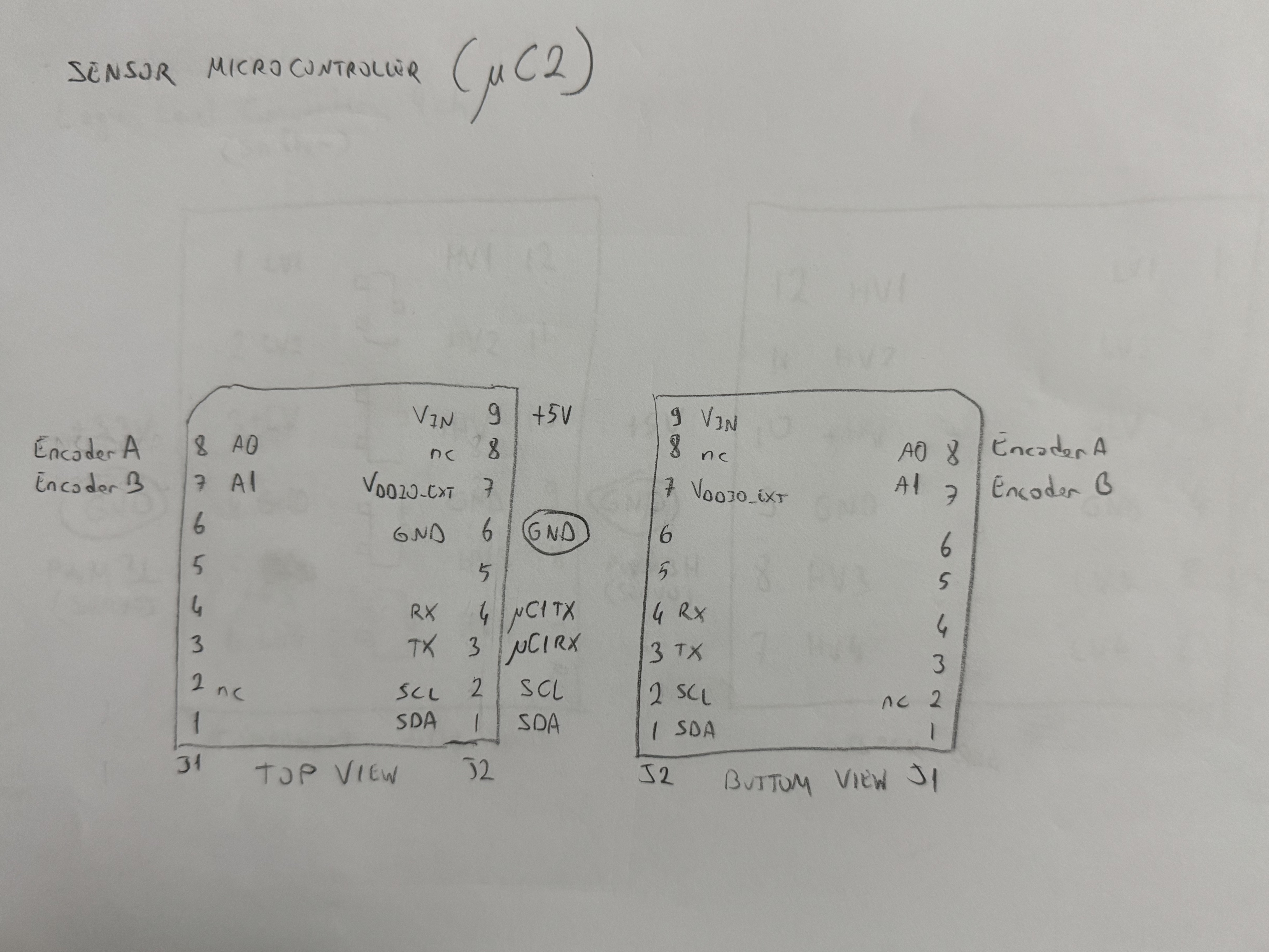
| **nRF52832 Sensor Processor**
ToF sensors and sensor fusion integration | [View Details](schemes/README.md#microcontroller-systems) |
|
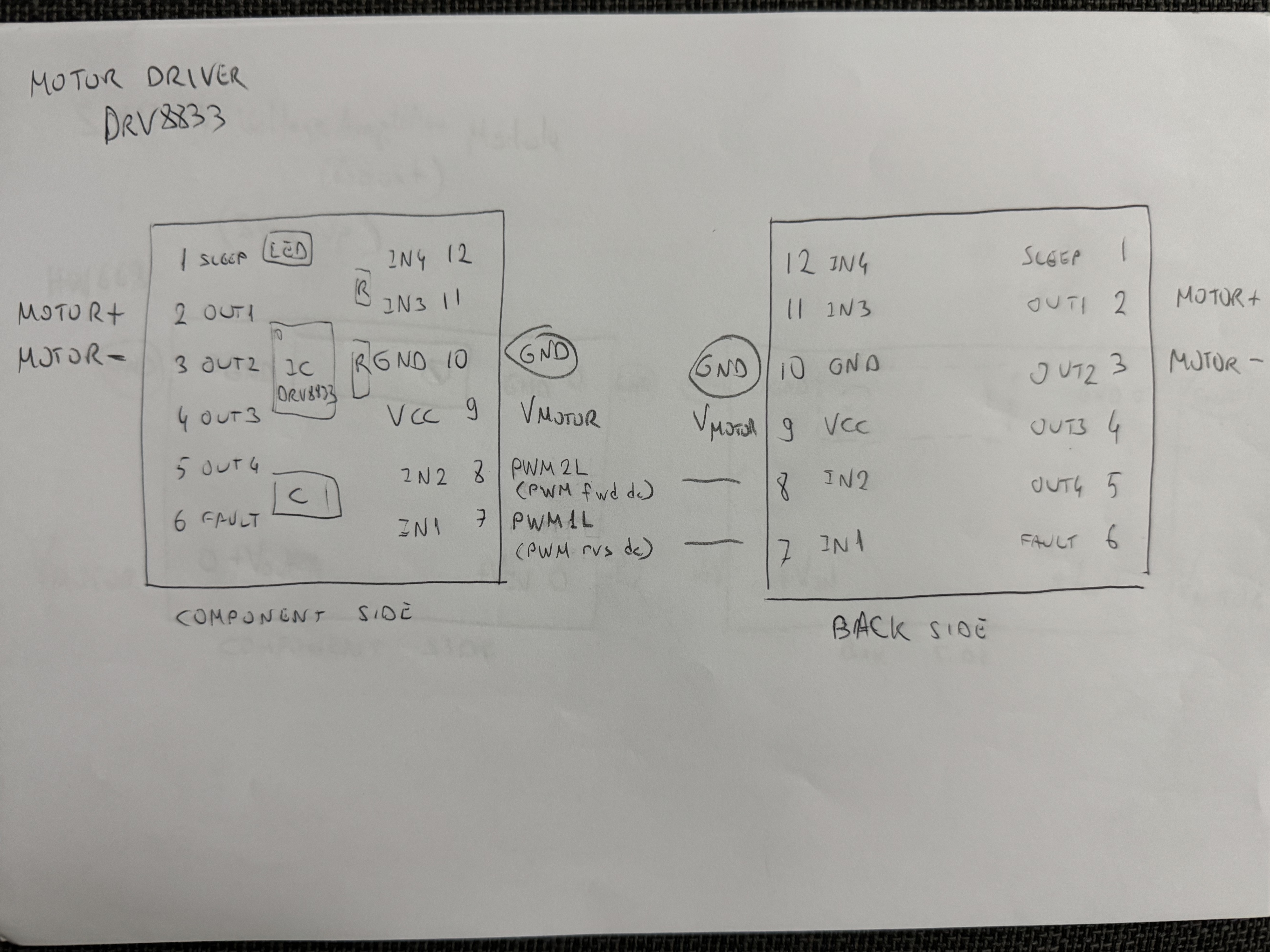
| **DRV8833 Motor Driver**
Motor control that uses SX1308 voltage boosting | [View Details](schemes/README.md#motor-control-systems) |
|
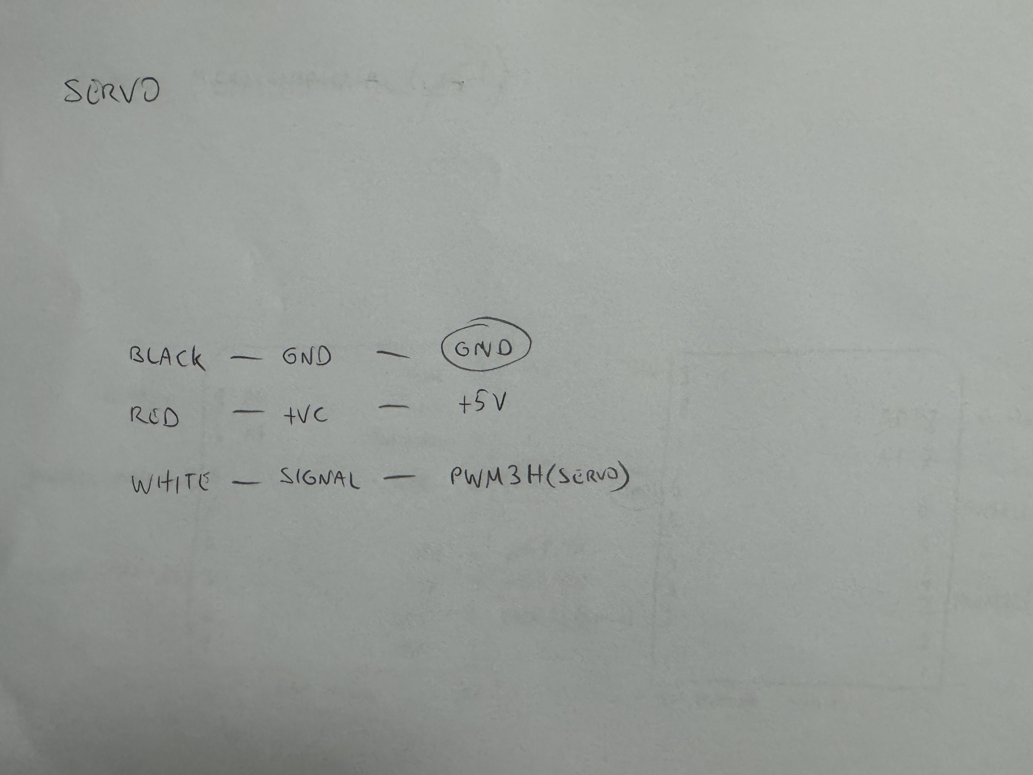
| **FS0307 Servo Control**
Steering mechanism that uses BOB-12009 level conversion | [View Details](schemes/README.md#motor-control-systems) |
|
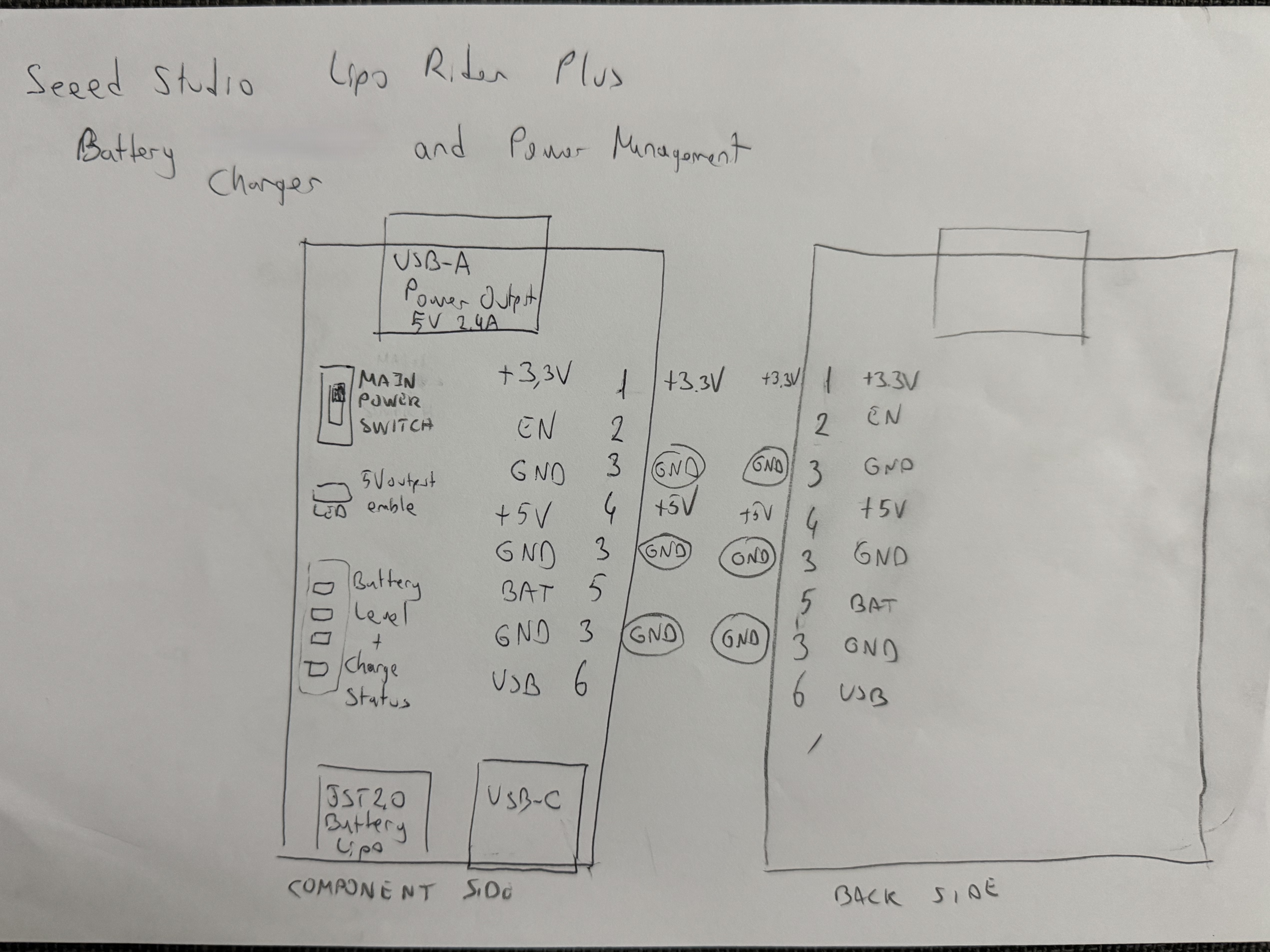
| **Power Management System**
LiPo charging and distribution | [View Details](schemes/README.md#power-management-components) |
|
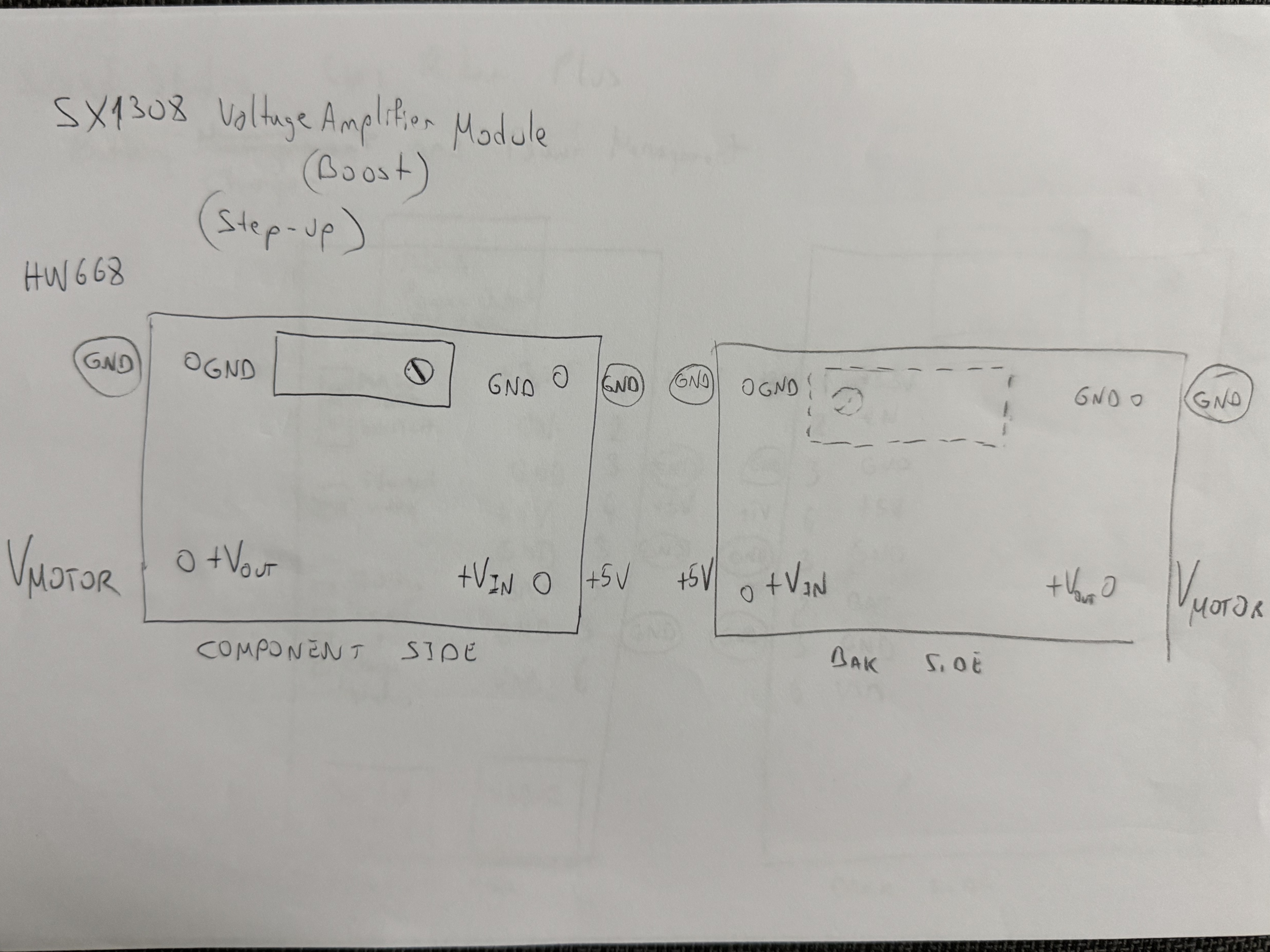
| **SX1308 Voltage Booster**
Motor power regulation | [View Details](schemes/README.md#power-management-components) |
|
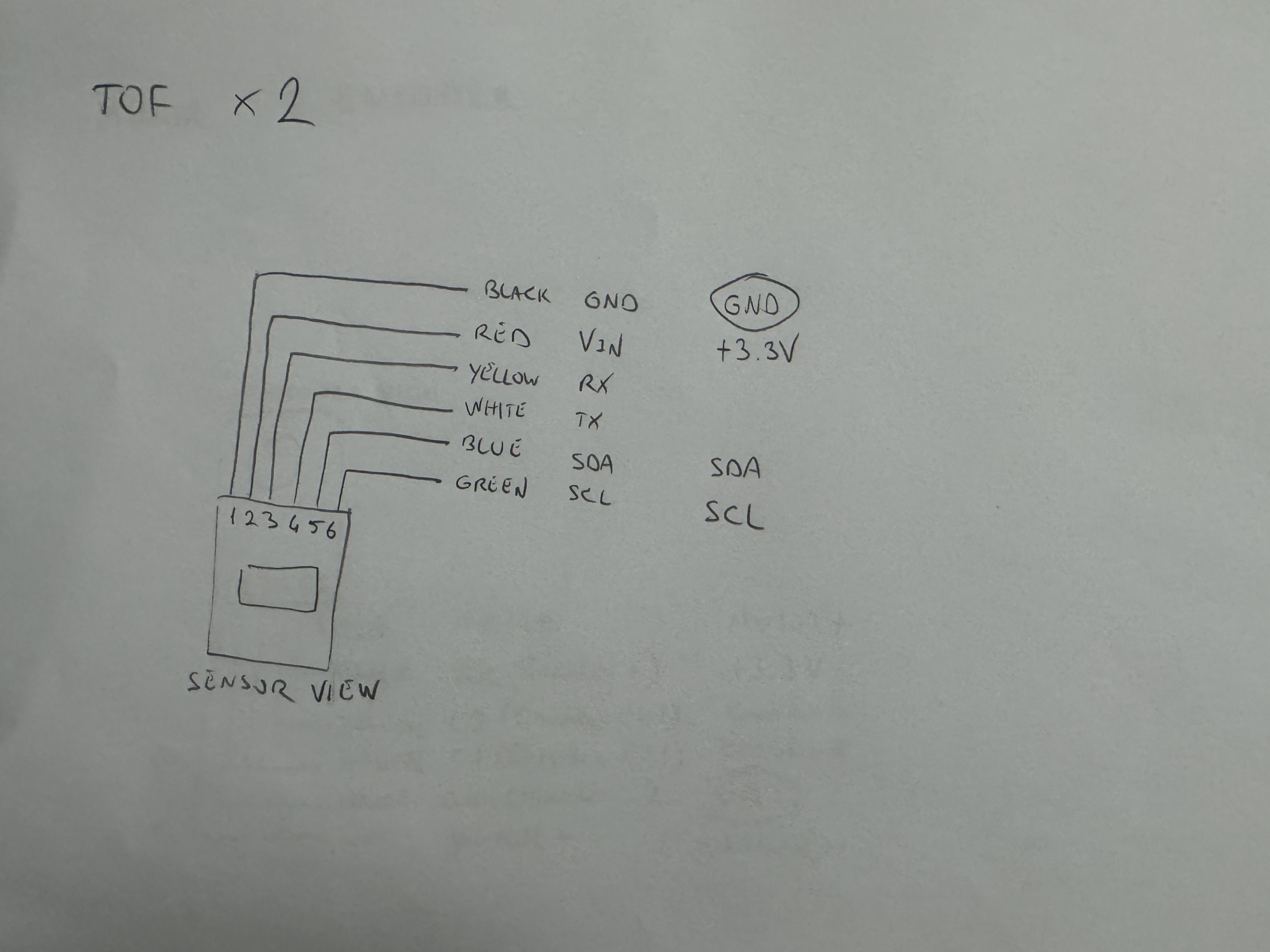
| **ToF Sensor Network**
Distance measurement system | [View Details](schemes/README.md#time-of-flight-sensor-system) |
|
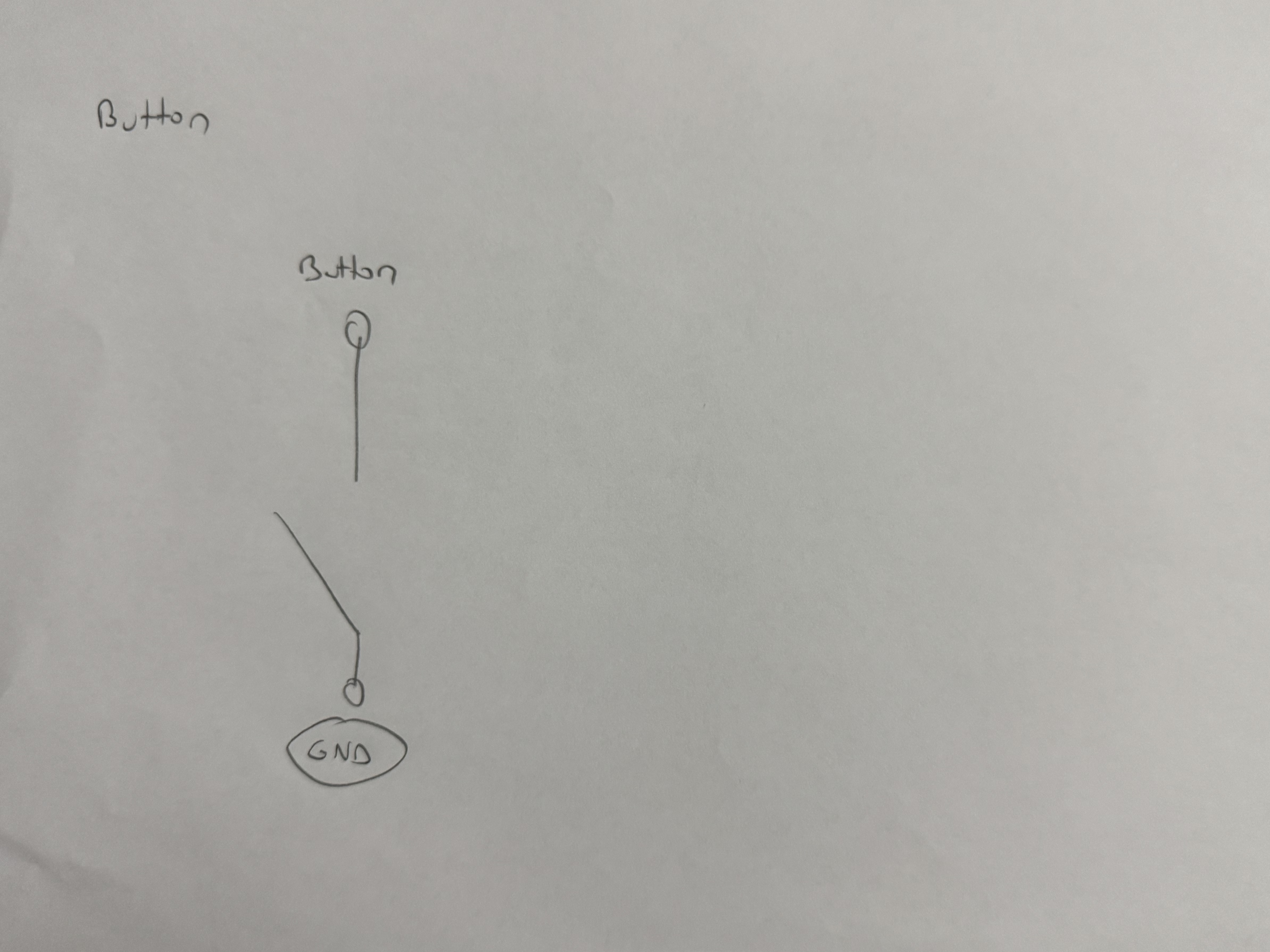
| **User Interface**
Start button and control interface | [View Details](schemes/README.md#-interface--control-systems) |
|
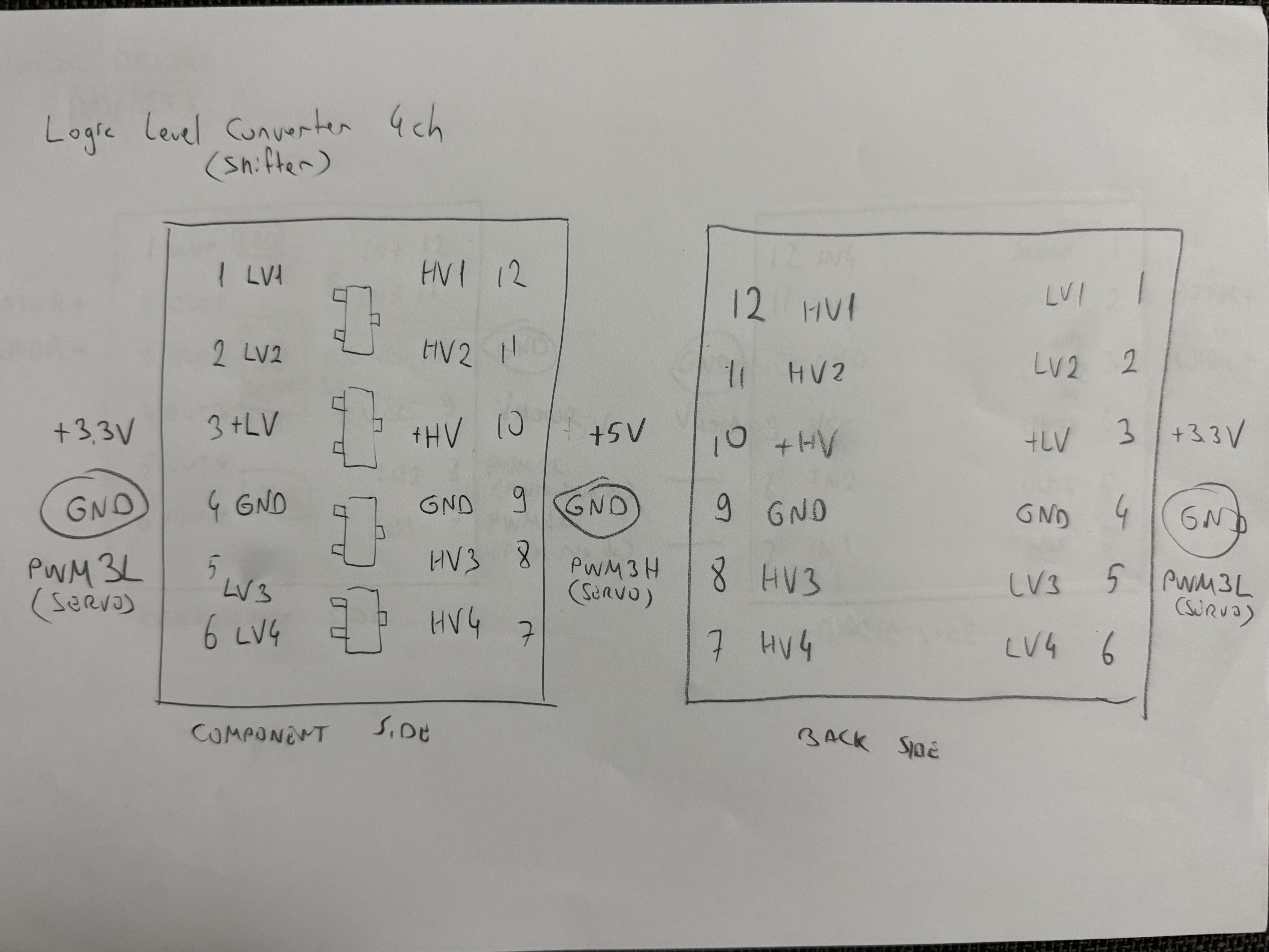
| **BOB-12009 Logic Level Converter**
3.3V-5V signal conversion for servo | [View Details](schemes/README.md#-interface--control-systems) |
|
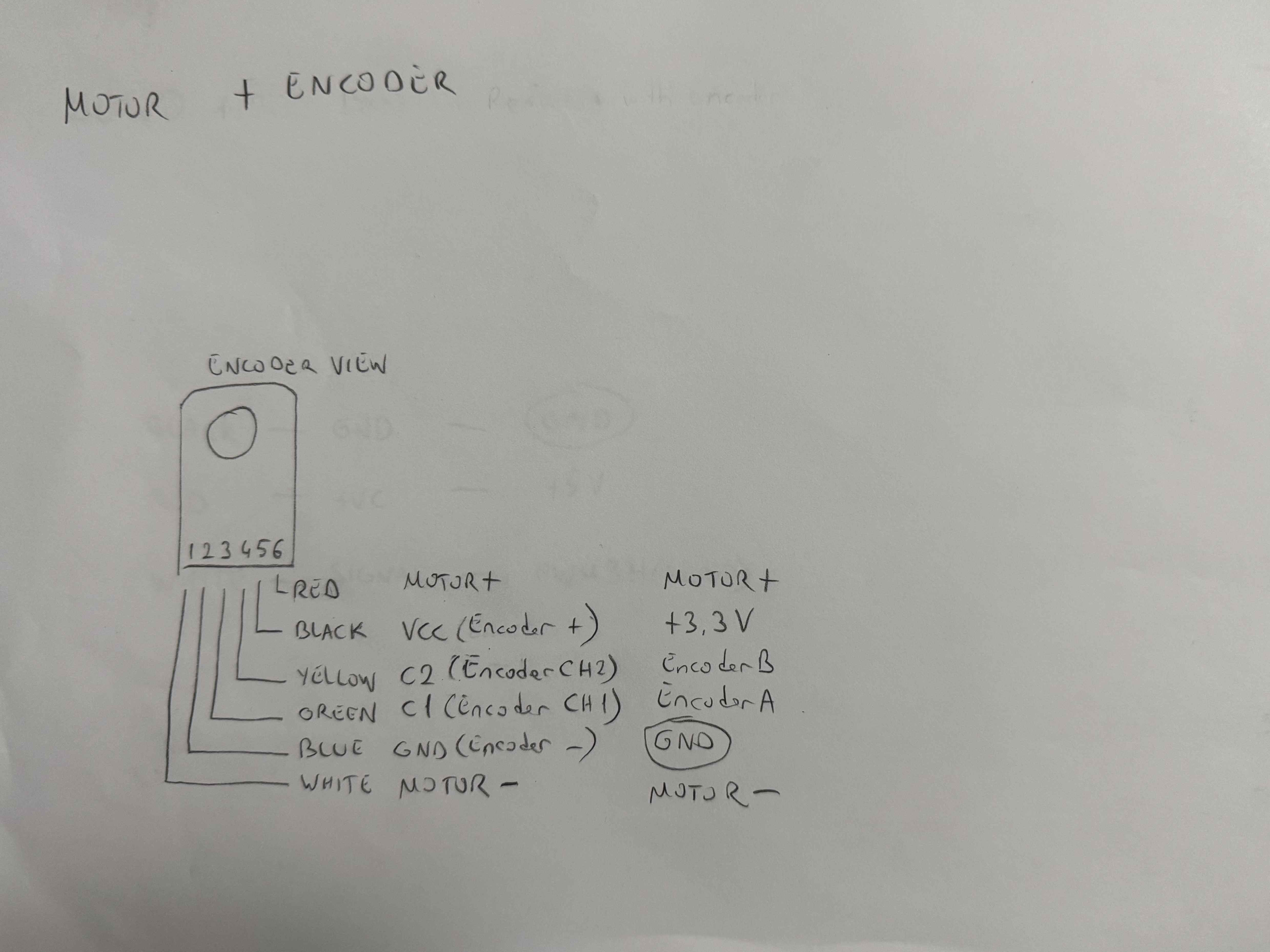
| **N20 DC Motor + Encoder**
Brushed DC motor with Hall effect encoder | [View Details](schemes/README.md#motor-control-systems) |
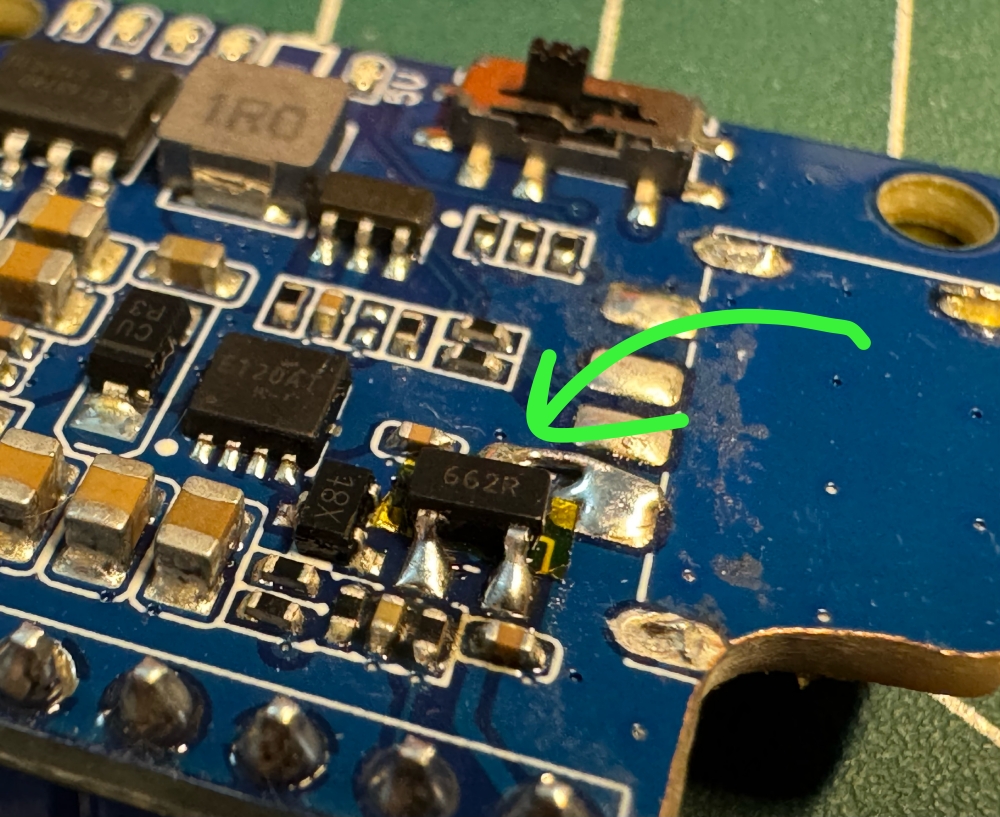
Hardware modification enabling complete power rail control through single switch
### **Signal Integrity Systems**
The **BOB-12009 logic level converter** ensures reliable communication between our 3.3V microcontrollers and 5V servo system. This implementation prevents signal degradation and ensures precise servo positioning under all operating conditions.
### **Thermal Performance Validation**
Comprehensive thermal analysis confirmed optimal operating temperatures across all critical subsystems:
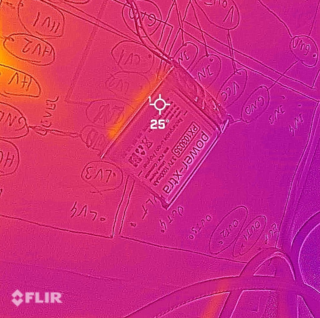
Power Cell: 25°C |
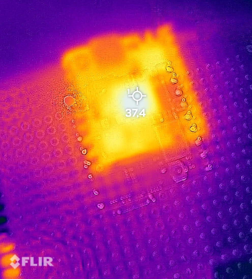
Processor: 37°C |
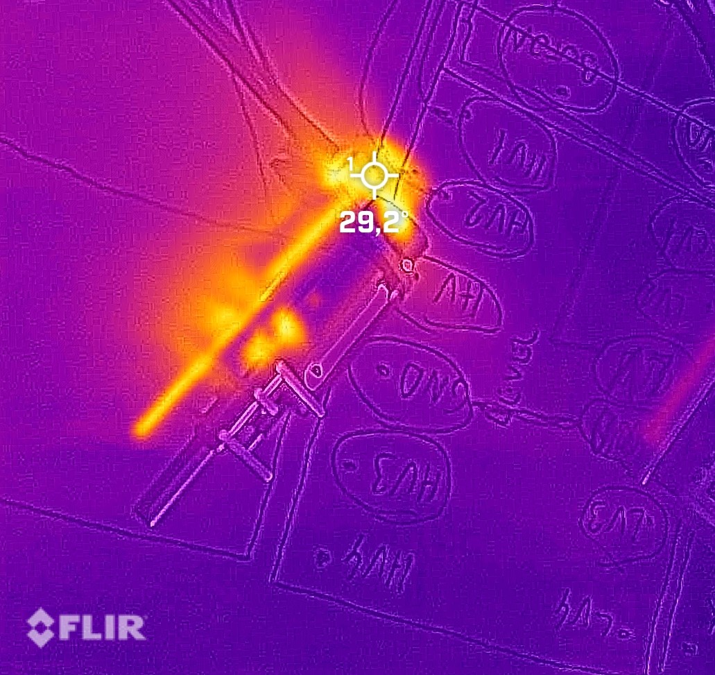
Drive Unit: 29°C |
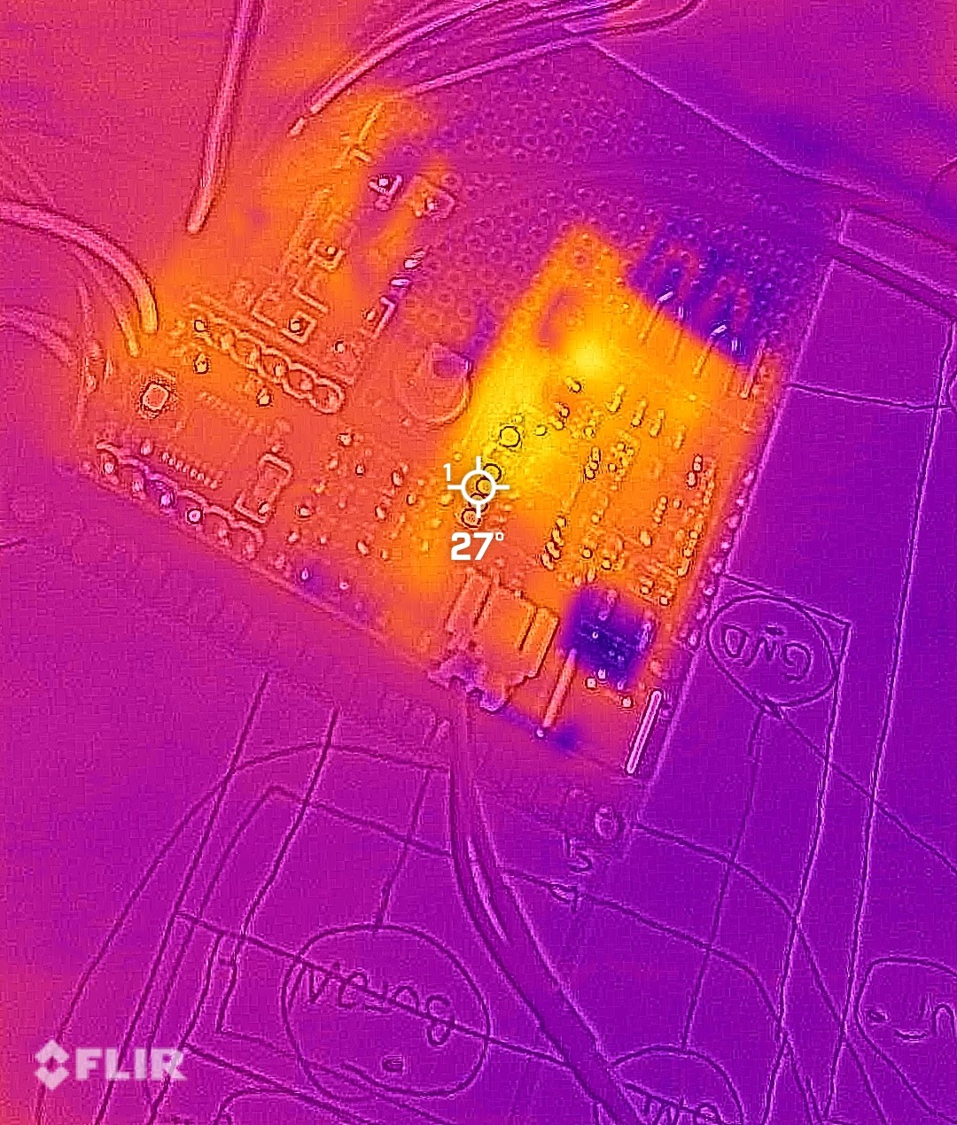
Power IC: 27°C |
### **Custom Manufacturing Approach**
Facing extreme space constraints, we developed an innovative double-layer pertinax board solution inspired by multi-layer PCB technology. This approach allowed complete in-house manufacturing while providing invaluable hands-on experience in circuit design and fabrication.
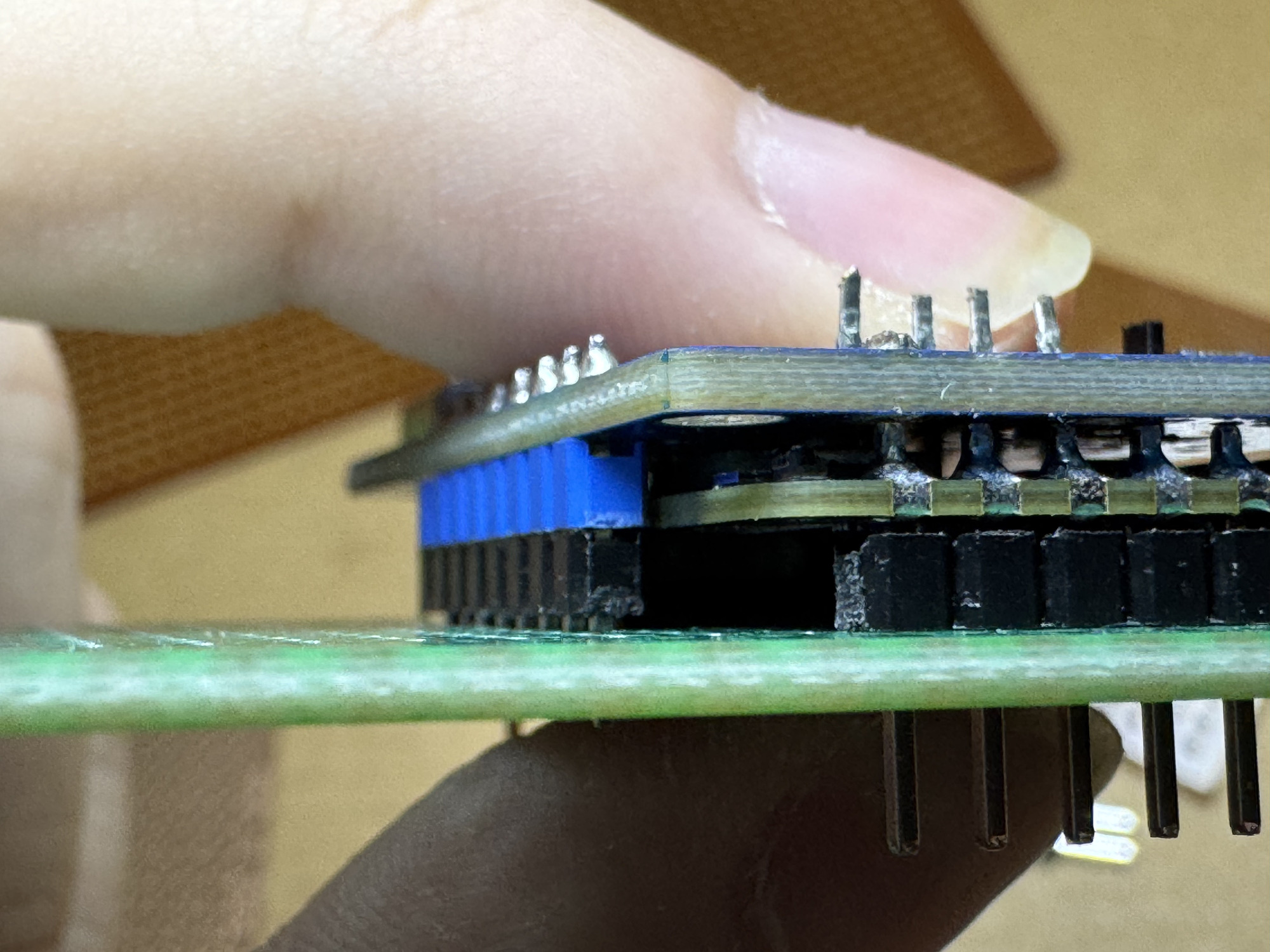
Custom double-layer pertinax implementation with component stacking
**Manufacturing Benefits**:
- **Rapid Iteration**: Immediate design modifications without external fabrication delays
- **Cost Efficiency**: Significant reduction compared to professional PCB services
- **Educational Value**: Comprehensive understanding of circuit construction and troubleshooting
- **Maintenance Advantage**: Socket-based design enables component-level serviceability
**Insulation Strategy**: Kapton tape application between layers prevents electrical contact while maintaining mechanical stability.
### **Sensor Integration Challenges**
Our minimal vertical profile created unique challenges for Time-of-Flight sensor implementation. The proximity to ground plane caused premature ground intersection in the sensors' field of view, limiting effective detection range.
**Optical Solution**:
- **Angular Adjustment**: Upward sensor tilt to delay ground intersection
- **Optical Modification**: Custom window lenses to narrow field of view
- **Performance Improvement**: Extended usable detection range from ~150cm to ~300cm
### **Development Convenience Features**
Implementation of magnetic USB connectors for programming interfaces significantly improved development workflow efficiency, allowing rapid code iterations without physical connector wear.
Easy-access programming interface with magnetic connection system
### **Performance Specifications**
- **Maximum Theoretical Speed**: 1.72 m/s (calculated from motor RPM and drive train ratios)
- **Operational Speed**: 1.4 m/s (PWM controlled for stability optimization)
- **Battery Endurance**: 4-5 hours typical operation
- **Charge Duration**: ~45 minutes via USB-C fast charging
- **Power Consumption**: 0.8W minimum, 200-250mA typical operational current
### Powertrain – Potential Improvements
- Switch to higher RPM coreless motor + greater 50:1 Micro Metal Gearbox → theoretical top speed > 2.3 m/s while keeping the same design.
- Replace the 26:25 external gear with an internal planetary stage inside the N20 motor can → saves 4 mm length with direct mounting of the motor to the rear axle.
- Active cooling (micro 10 mm fan, 0.8 g) → could improve the overall airflow in the system, allowing for faster operation and even higher stability.
---
## ⚙ **Mechanical Systems**
Our mechanical design philosophy centers on achieving maximum capability within minimal dimensions through innovative engineering and precision manufacturing.
### **Core Mechanical Specifications**
- **Overall Dimensions**: 69mm (L) × 53mm (W) × 57mm (H)
- **Total Mass**: Approximately 130 grams
- **Structural Material**: 3D-printed ABS for optimal strength-to-weight ratio
- **Drive Configuration**: Rear-wheel drive with custom differential
- **Steering System**: True Ackermann geometry with precision linkage
### **Design Integration Approach**
Digital design precision translated to physical implementation through advanced manufacturing techniques
### **Steering Geometry Implementation**
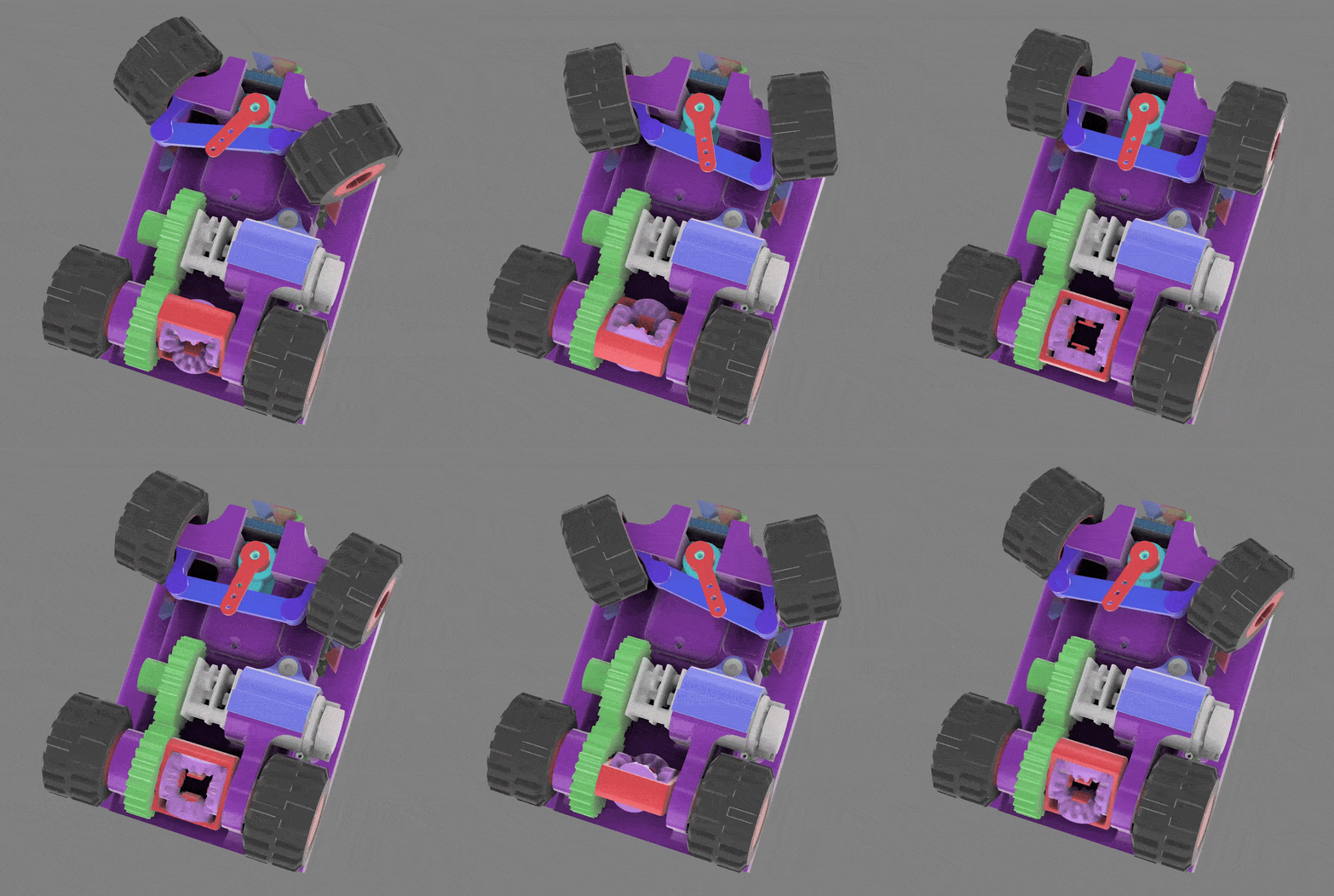
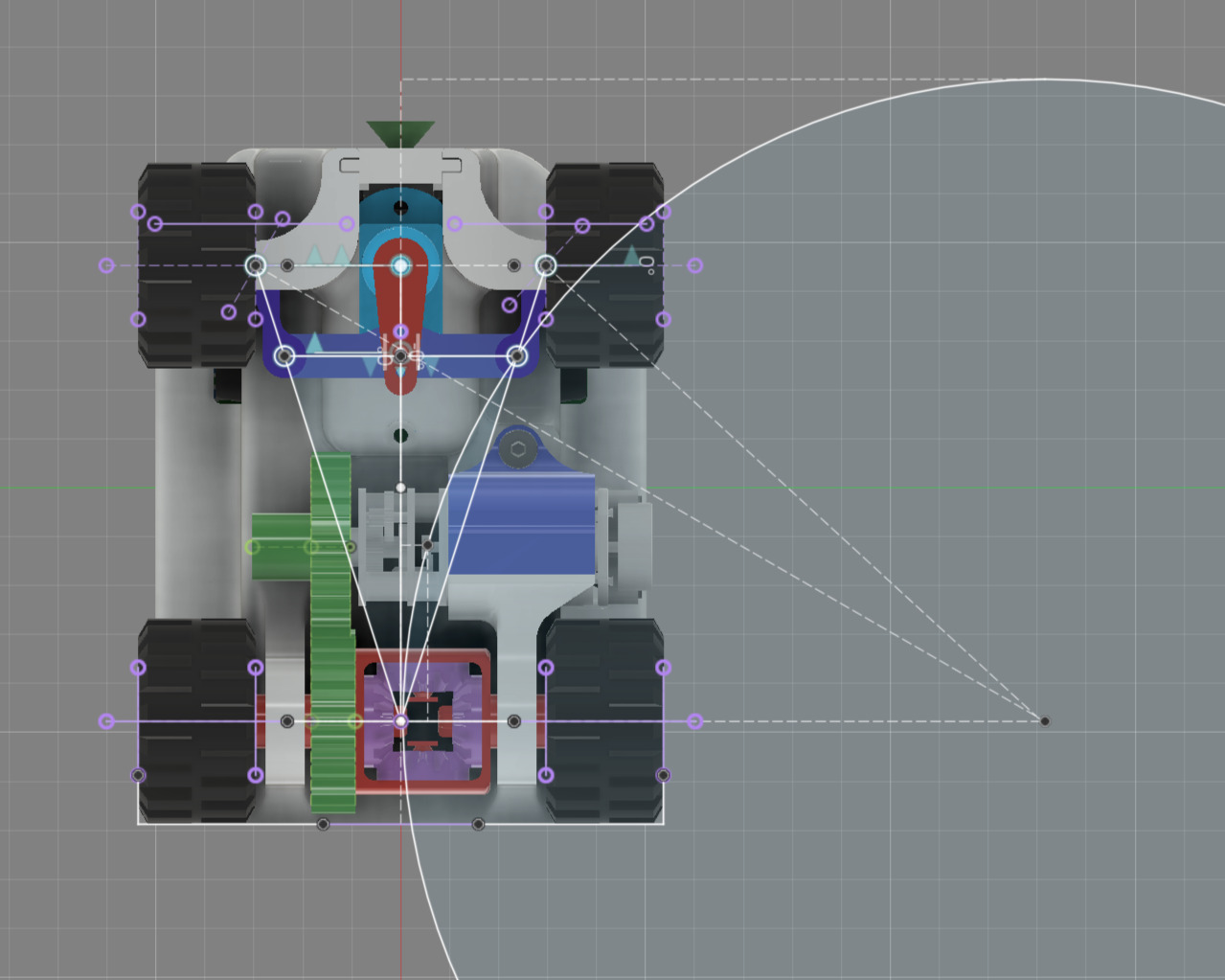
Our custom Ackermann steering system ensures each wheel maintains optimal alignment during turns, minimizing tire scrub and maximizing maneuverability.
Dynamic steering simulation and geometric analysis ensuring optimal turning performance
**Steering System Evolution**:
- **Initial Concept**: Integrated print-in-place mechanism for rapid prototyping
- **Performance Refinement**: Multi-component assembly for long-term precision
- **Final Implementation**: Four M2 fasteners with locking nuts for permanent alignment
- **Wheel Articulation**: -50° to +32° range optimized for competition track dimensions
### Mechanical – Potential Improvements
- True Ackermann geometry with adjustable tie-rod lengths for further adjustability.
- Ball bearings on all four kingpins and differential gears → theoretical 7–9 % less rolling resistance in CAD tests.
- Possible uspension system using micro torsion bars could improve stability if the track includes ground obstacles in the future when crossing the 3 mm track.
### **Power Transmission System**
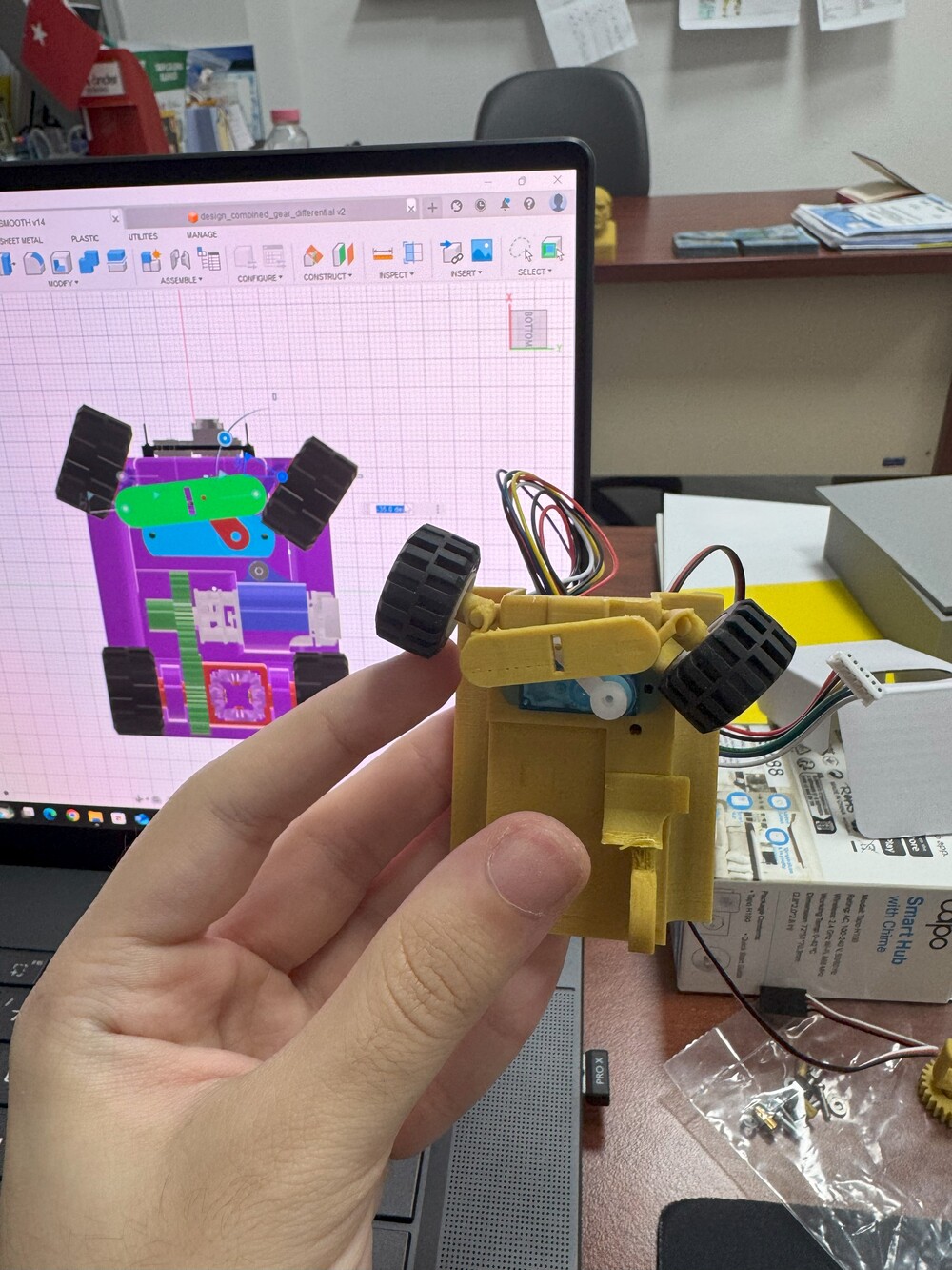
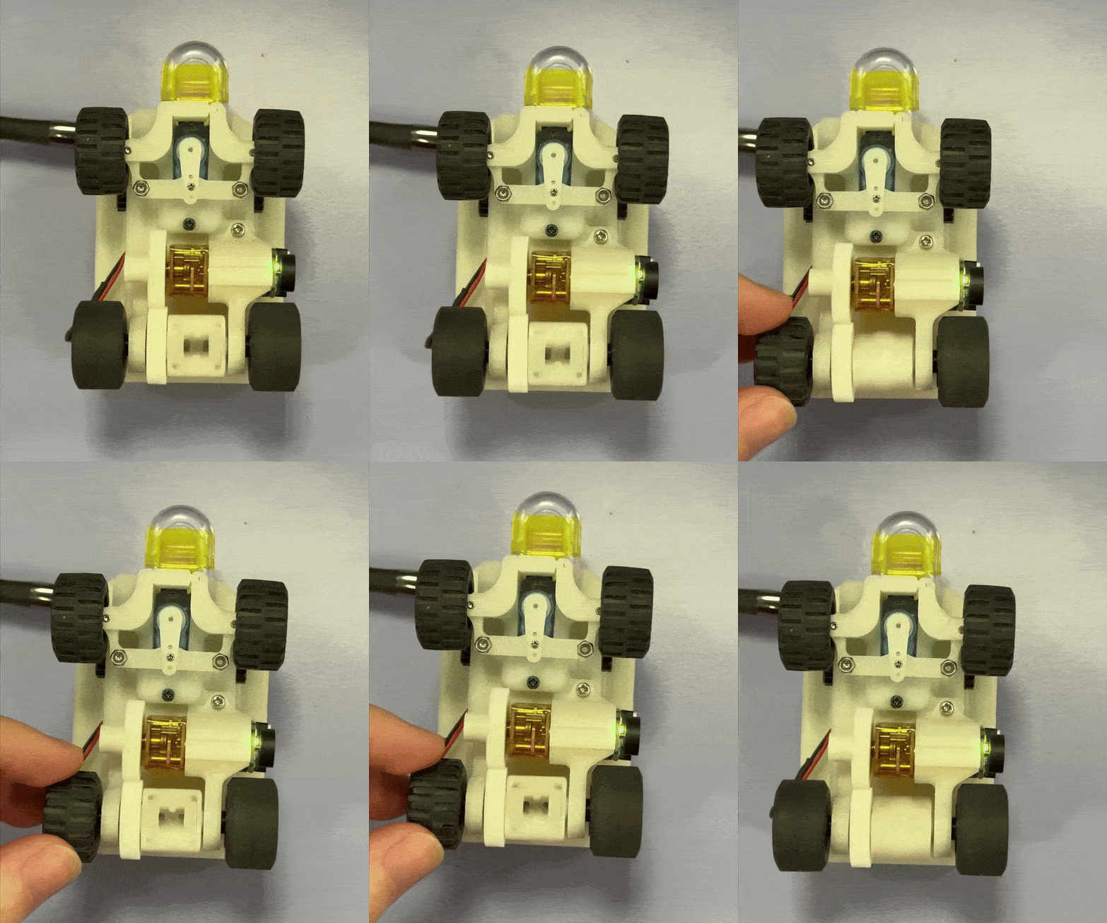
The custom 4-gear differential ensures smooth torque distribution during turning maneuvers, preventing wheel slip and maintaining traction.
Physical validation of differential operation and comprehensive CAD documentation
**Gear System Architecture**:
- **Speed Reduction**: 26:25 ratio through custom spur gear design
- **Torque Distribution**: Four 12-tooth bevel gears enabling independent wheel rotation
- **Manufacturing Precision**: 100% infill for maximum durability under load
- **Efficiency Optimization**: Precisely calculated tooth profiles for minimal power loss
### **Manufacturing File Repository**
*All components provided in 3MF format for maximum compatibility across different 3D printing platforms and slicing software*
### **Performance Engineering Analysis**
**Drive Train Calculations**:
- **Motor Specification**: 1500 RPM N20 DC motor with quadrature encoder
- **Gear Reduction**: 26:25 ratio providing optimal speed-torque balance
- **Theoretical Maximum Velocity**: 1.72 m/s derived from wheel geometry and drive ratios
- **Operational Velocity**: 1.4 m/s selected for optimal control stability
**Structural Analysis**:
- **Motor Torque Capacity**: ~0.25 Nm at 6V, sufficient for 130g vehicle acceleration
- **Bearing System**: Four precision bearings minimizing rotational friction
- **Steering Load Management**: Mechanism optimized for servo torque characteristics
- **Impact Resistance**: Validated through comprehensive testing under competition conditions
### **Assembly Methodology**
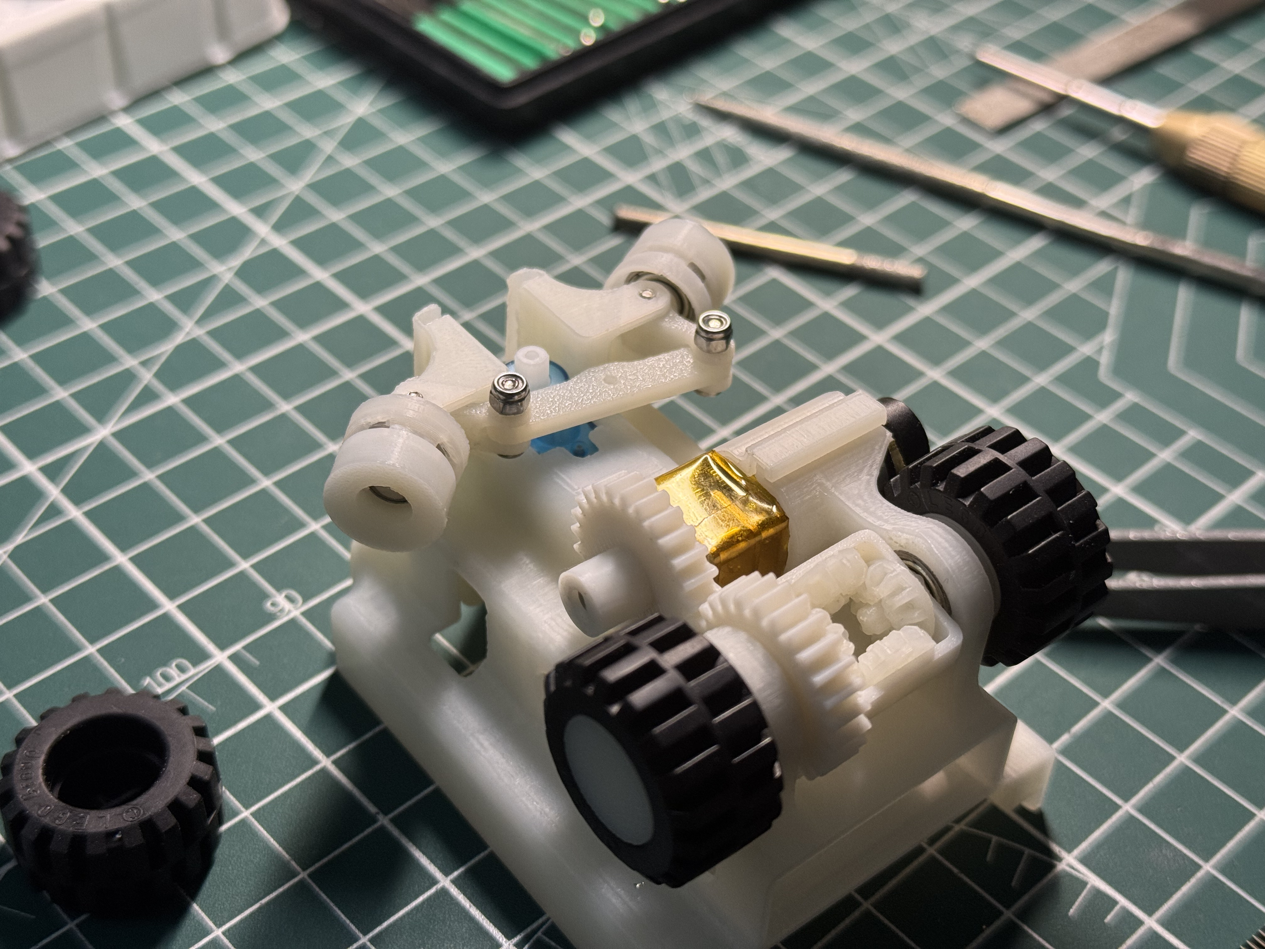
Staged assembly approach ensuring proper system integration and alignment
**Assembly Sequence**:
1. **Drive System Integration**: Differential assembly and motor mounting with M2 hardware
2. **Steering Mechanism Installation**: Ackermann linkage and servo integration
3. **Wheel System Assembly**: Bearing installation and wheel mounting
4. **Electronic System Integration**: Pertinax board installation and component connection
5. **Final System Validation**: Comprehensive functional testing and alignment verification
---
## 💻 **Software Architecture**
Our software implementation employs a distributed processing architecture that optimizes performance through specialized task allocation between multiple processors.
### **System Architecture Overview**
|
**Processing Distribution**:
- **Vision Processing Unit**: STM32H747 handling real-time image analysis and high-level decision making
- **Sensor Fusion Unit**: nRF52832 managing multi-sensor data acquisition and preprocessing
- **Communication Bridge**: Bidirectional UART protocol at 115200 baud for inter-processor data exchange
**Core Software Components**:
- [`open.py`](src/open.py) - Open challenge navigation algorithms
- [`obstacle.py`](src/obstacle.py) - Obstacle challenge with integrated parking
- [`uart_slave.ino`](src/uart_slave.ino) - Sensor management firmware
|
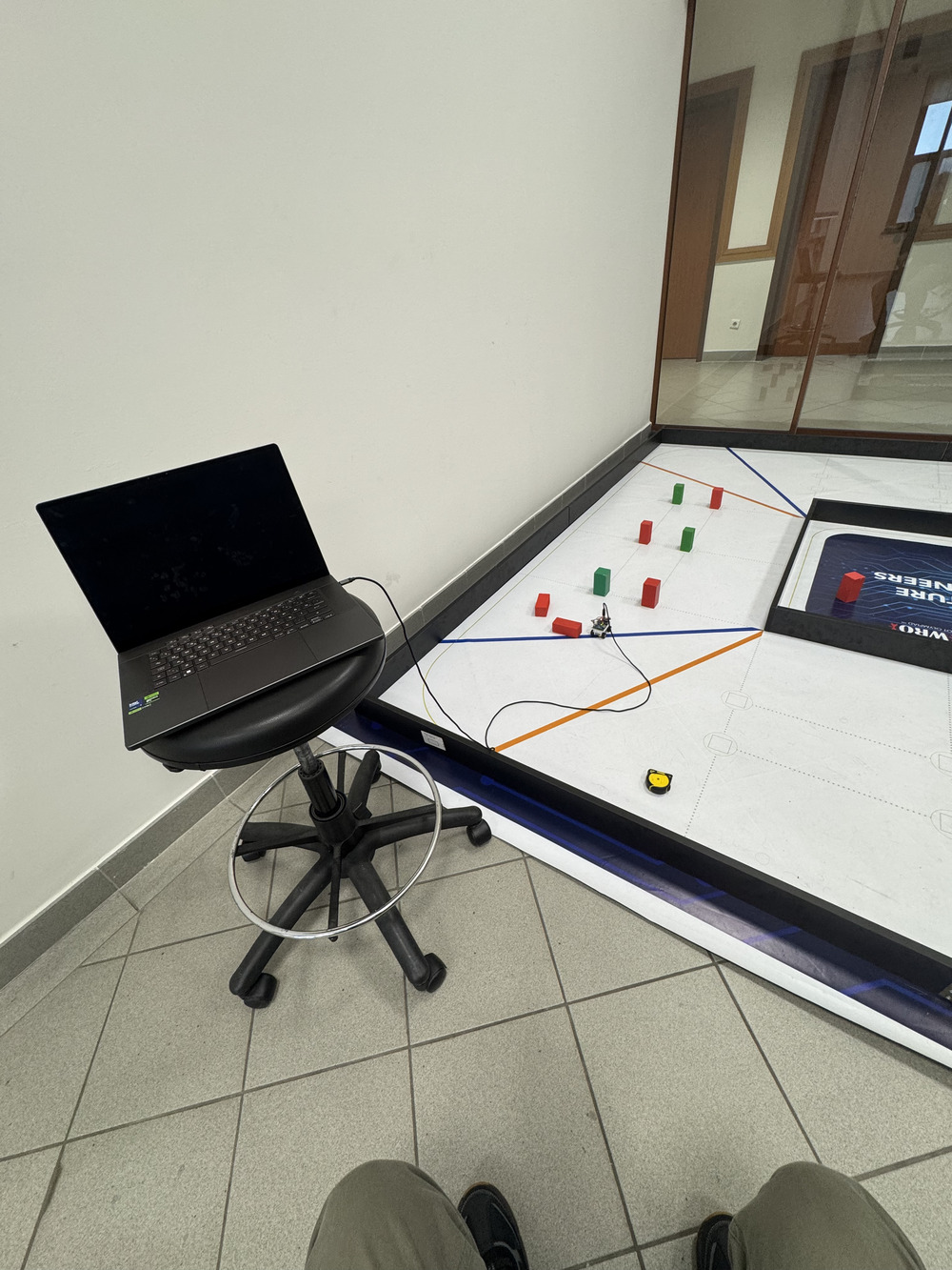
Integrated development and testing setup
|
### 💾 **Development Environment & Code Deployment**
#### **STM32H747 (Camera Microcontroller)**
- **Programming Language**: MicroPython for rapid development and testing
- **Development Interface**: Direct micro USB connection to evaluation board
- **Core Libraries**:
- `machine` - Hardware abstraction for PWM, GPIO, and UART control
- `pyb` - STM32-specific peripheral functions and timer management
- `sensor` - Camera interface and real-time image processing
#### **nRF52832 (Sensor Microcontroller)**
- **Programming Language**: Arduino C++ for efficient sensor data handling
- **Development Interface**: Standard micro USB connection to evaluation board
- **Essential Libraries**:
- `Wire.h` - I2C communication protocol for sensor networks
#### **Development Workflow Optimization**
We implemented magnetic USB connectors for the camera microcontroller, providing significant advantages during intensive development cycles. The magnetic interface enables rapid connection changes, prevents physical port damage from repeated use, and streamlines the programming and debugging process.
#### **Code Deployment Process**
1. **STM32H747 MicroPython Deployment**:
- Transfer `.py` source files directly to microcontroller filesystem using magnetic USB connection
- Automatic execution initialization from `main.py` on system startup
- No compilation overhead - immediate interpreted execution for rapid iteration
2. **nRF52832 Arduino Deployment**:
- Compile source code in Arduino IDE with nRF5 board package support
- Upload compiled binary via micro USB interface to evaluation board
- Precompiled firmware deployment ensuring reliable sensor operation
### 🎨 **Vision Processing Strategy**
We selected the **CIELAB color space** for its superior performance under variable lighting conditions compared to traditional RGB or HSV representations. Our custom MATLAB analysis tool systematically determines optimal detection thresholds.
**Technical Rationale**: LAB colorspace provides adequate performance for our application requirements, while machine learning approaches would introduce unnecessary complexity without significant benefits for this specific use case.
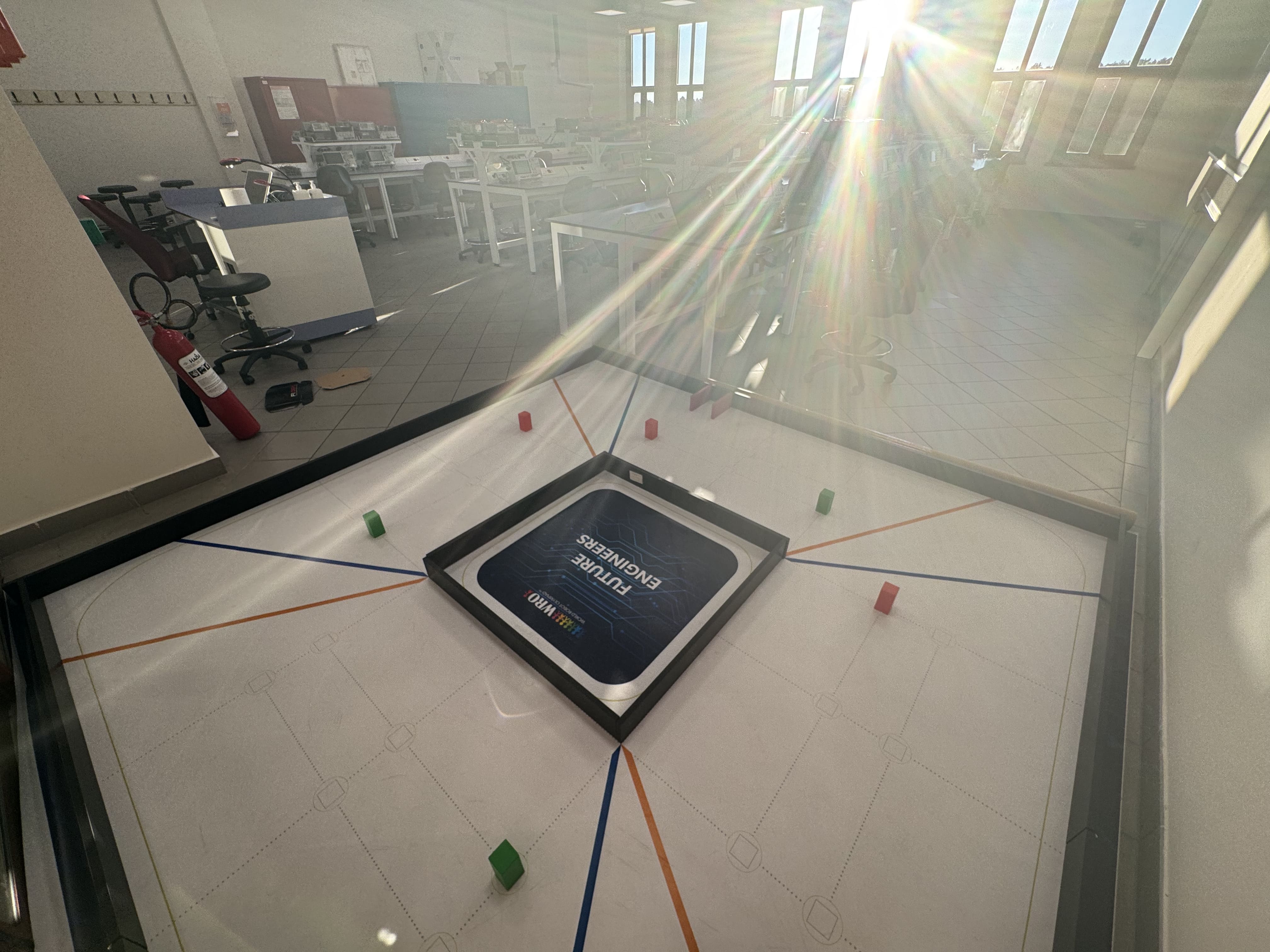
Comprehensive testing under challenging lighting conditions including direct sunlight exposure
### 🧭 **Navigation Algorithm Implementation**
#### **Open Challenge Navigation**
**State Machine Flow**:
```
Initial Forward → Follow Wall → Turn Corner → Follow Wall (repeat)
↑ ↑ ↑ ↑
ToF + Color Camera PID IMU 90° Turn Continue
Detection Wall Tracking Navigation
```
**Open Challenge Pseudocode**:
```
INITIALIZE sensors, set direction = unknown
WHILE direction == unknown:
DRIVE forward using IMU guidance
DETECT orange/blue colors
IF orange detected first: SET direction = clockwise
IF blue detected first: SET direction = counterclockwise
IF front ToF < 800mm: TRANSITION to wall following
WHILE corner_count < 12:
FOLLOW inner wall using camera PID
DETECT orange/blue corners
IF corner detected: INCREMENT corner_count
IF wall lost and min_distance traveled: EXECUTE 90° turn
UPDATE odometry and heading
EXECUTE final forward movement
STOP
```
#### **Obstacle Challenge Strategy**
**Multi-State Operation**:
```
Determine Direction → Follow Color → Lost Color → Pass Color → U-Turn → Parking
↑ ↑ ↑ ↑ ↑ ↑
ToF + Color Camera PID Search Avoidance 180° Turn Magenta
Detection Color Track Pattern Maneuver Maneuver Detection
```
**Obstacle Challenge Pseudocode**:
```
INITIALIZE sensors
DETERMINE direction using side ToF sensors
EXECUTE initial alignment maneuver
WHILE corner_count < 13:
NAVIGATE using camera color detection
IF red detected: FOLLOW with right offset
IF green detected: FOLLOW with left offset
IF color lost: SEARCH pattern
IF color not found: PASS obstacle maneuver
DETECT orange/blue corners for lap counting
EXECUTE 180° U-turn maneuver
APPROACH parking zone
DETECT magenta parking marker
EXECUTE parallel parking sequence
STOP
```
**Color-Specific Behaviors**:
- **Red Object Detection**: Right-side bias navigation with maintained offset
- **Green Object Detection**: Left-side bias navigation with maintained offset
- **Position Maintenance**: Consistent pixel positioning for smooth obstacle tracking
### **Sensor Fusion Implementation**
**Data Integration Pipeline**:
```
nRF52832 Sensors ←→ UART ←→ STM32H747 → Sensor Fusion → Control Decisions
↑ ↑ ↑ ↓
ToF Left Camera PID Controller Motor/Servo
ToF Right Vision State Machine Actuators
Encoder Data IMU Data
ToF Front
```
### **Control System Implementation**
**Steering Control Algorithm**:
```python
# PID controller implementation for smooth navigation
def calculate_steering_correction(vision_error, heading_error):
proportional = vision_error * KP_GAIN
integral = integrate_error(vision_error) * KI_GAIN
derivative = calculate_derivative(vision_error) * KD_GAIN
return proportional + integral + derivative
```
### **Bidirectional Inter-Processor Communication**
**UART Protocol Specification**:
- **Baud Rate**: 115200 for optimal data throughput
- **Command Structure**: Single-character commands with formatted responses
- **Data Validation**: Checksum verification and timeout handling
- **Error Recovery**: Automatic reinitialization on communication failure
**Master (STM32H747) → Slave (nRF52832) Commands**:
- `'r'` - Request all sensor data (left_tof, right_tof, encoder)
- `'t'` - Request left ToF sensor only
- `'u'` - Request right ToF sensor only
- `'e'` - Request encoder travel distance only
- `'z'` - Reset encoder counter to zero
**Slave Response Formats**:
- **All sensors**: `left_distance,right_distance,encoder_distance\n`
- **Left ToF only**: `left_distance\n`
- **Right ToF only**: `right_distance\n`
- **Encoder only**: `encoder_distance\n`
### **Parking Maneuver Analysis**
Our compact dimensions required innovative parking strategies to operate within the constrained parking space.
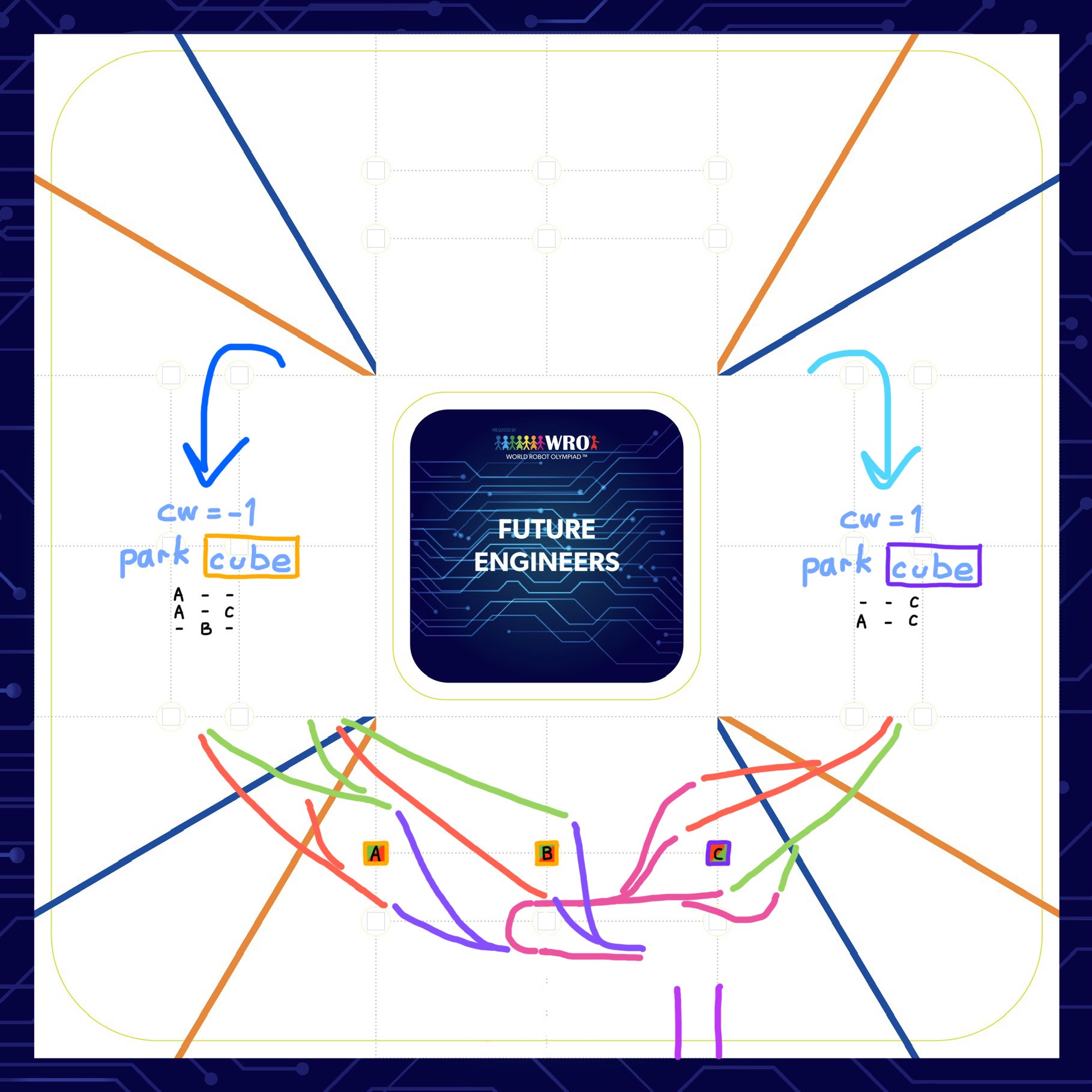
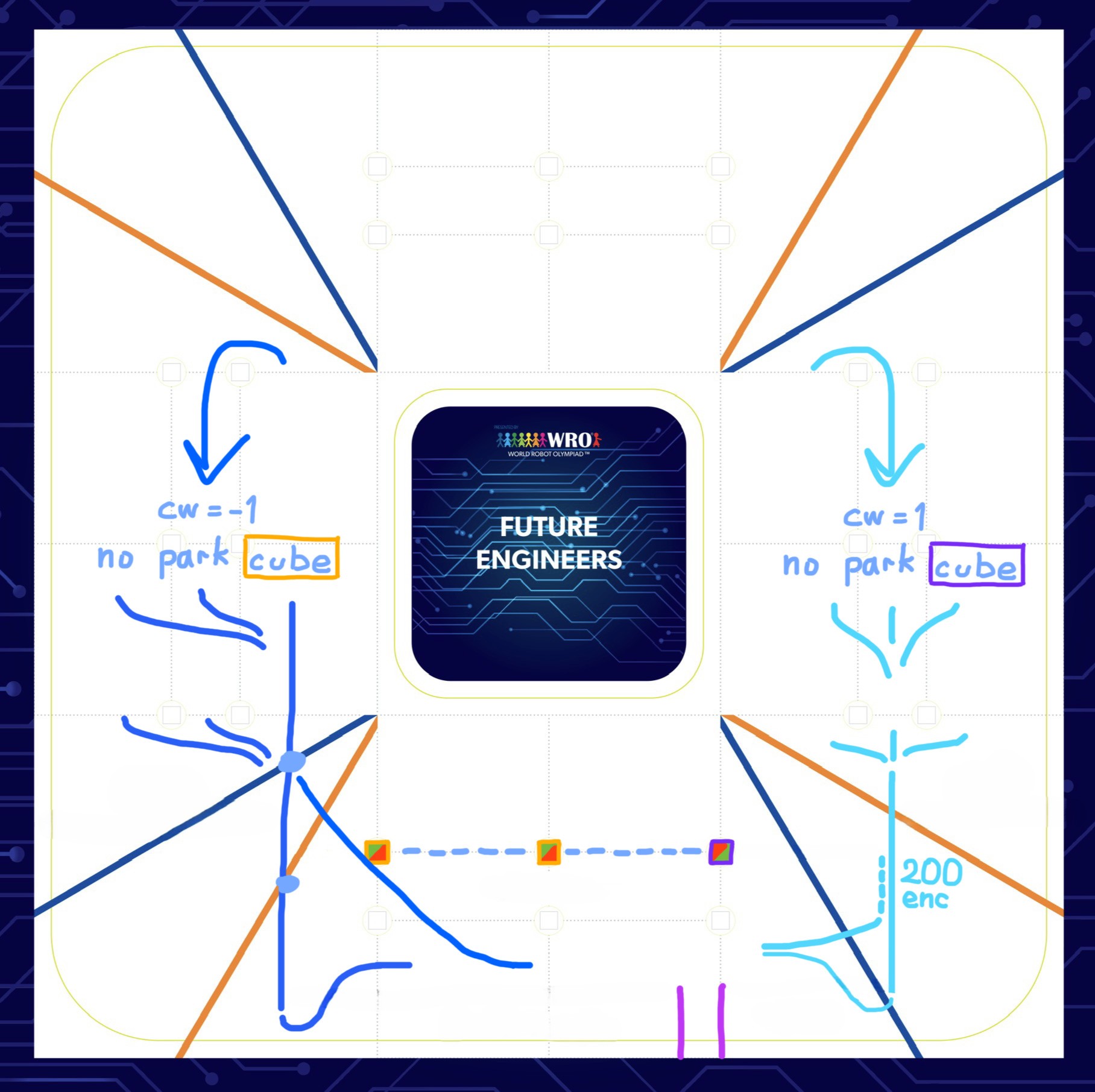
Parking strategy analysis for different final obstacle configurations
### **Parallel Parking Strategy Optimization**
**🚧 Challenge**: Our compact 69mm vehicle length required extremely precise maneuvers within the tight 1.5× vehicle length parking space (103.5mm)
**💡 Initial Solution**: We designed a strategic front extension piece providing crucial benefits:
- **📏 Length Optimization**: 21mm extension increased total length to 90mm
- **Parking Space Compliance**: Requirement became 90mm × 1.5 = 135mm
- **Critical Clearance Design**: Narrow extension width allowed wall clearance during turns
- **🔄 Maneuverability Enhancement**: Additional space enabled reliable parking execution
**Multi-Stage Parking Sequence**:
1. **Approach Phase**: Follow magenta wall using camera guidance
2. **Turn-in Execution**: 80-degree turn outside parking spot
3. **Alignment Phase**: Odometry-based reverse positioning
4. **Reverse Maneuver**: Controlled backing for final alignment
5. **Straighten Phase**: Final orientation adjustment
> 💡🐜 ***Team Identity Discovery***: The distinctive front extension piece created a visual resemblance to an **ANT**'s mandible, perfectly aligning with our team name and establishing a memorable identity!
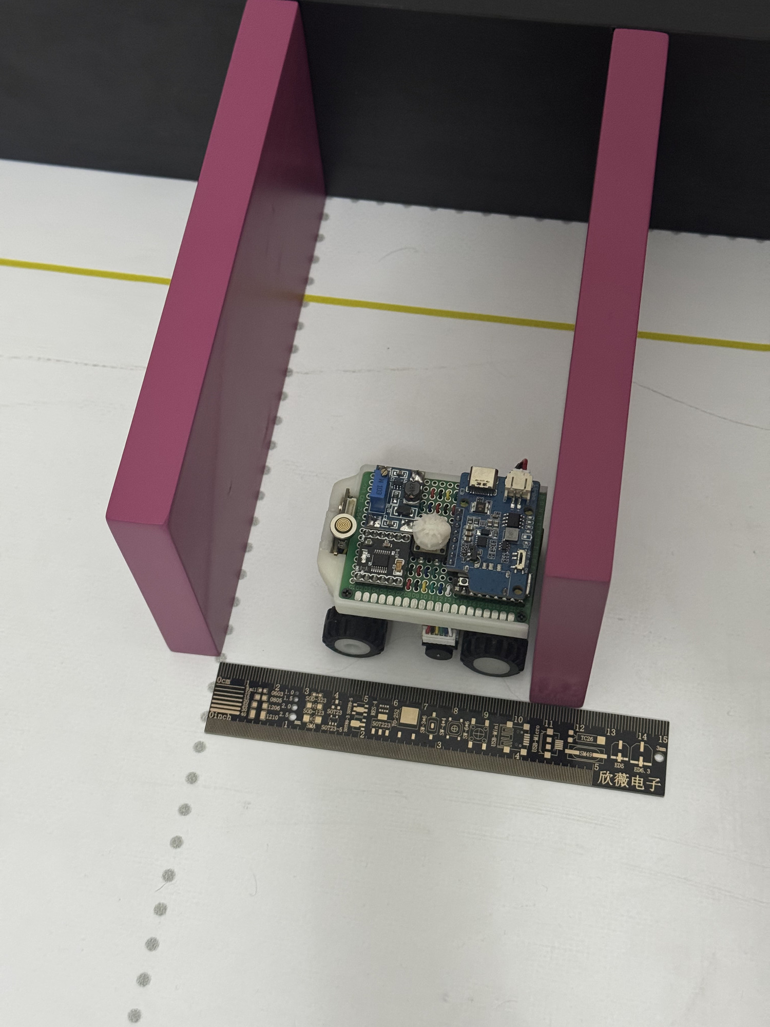
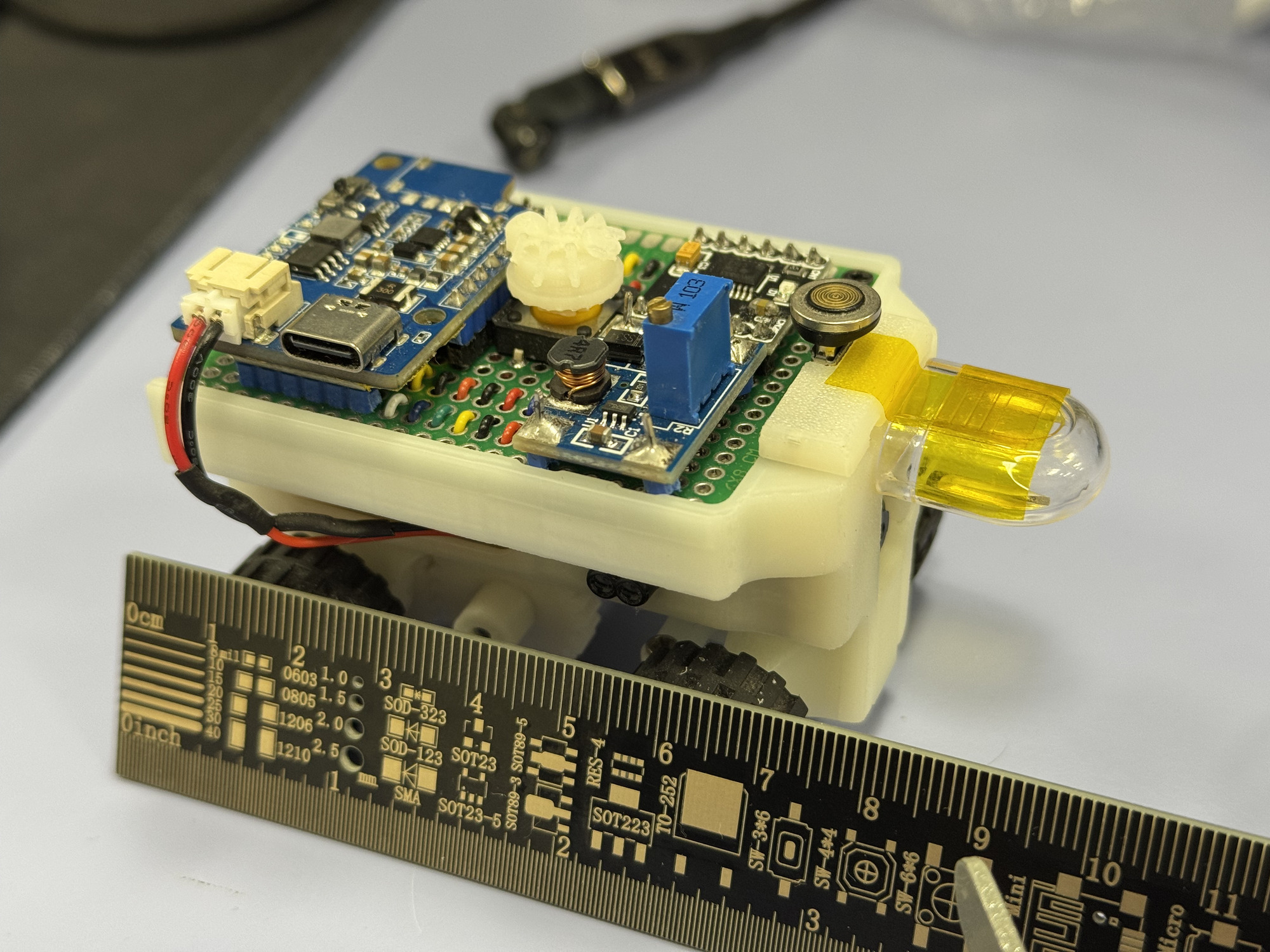
1) Original 69mm vehicle demonstrating parking constraints • 2) Extended 90mm vehicle with strategic front piece implementation
**💡 Final Evolution**: After extensive testing, we iterated on the extension design to further enhance safety and performance:
- **📏 Enhanced Length**: Increased extension to 41mm for total vehicle length of 110mm
- **Parking Space Adjustment**: Expanded requirement to 110mm × 1.5 = 165mm
- **Improved Safety Margin**: Greater clearance for multi-turn maneuvers while maintaining higher speeds
- **Design Refinements**: Incorporated competition stickers creating "ANTi" branding and ant-inspired eyes
- **Maneuver Strategy**: Retained multiple-turn parking for optimal speed-safety balance
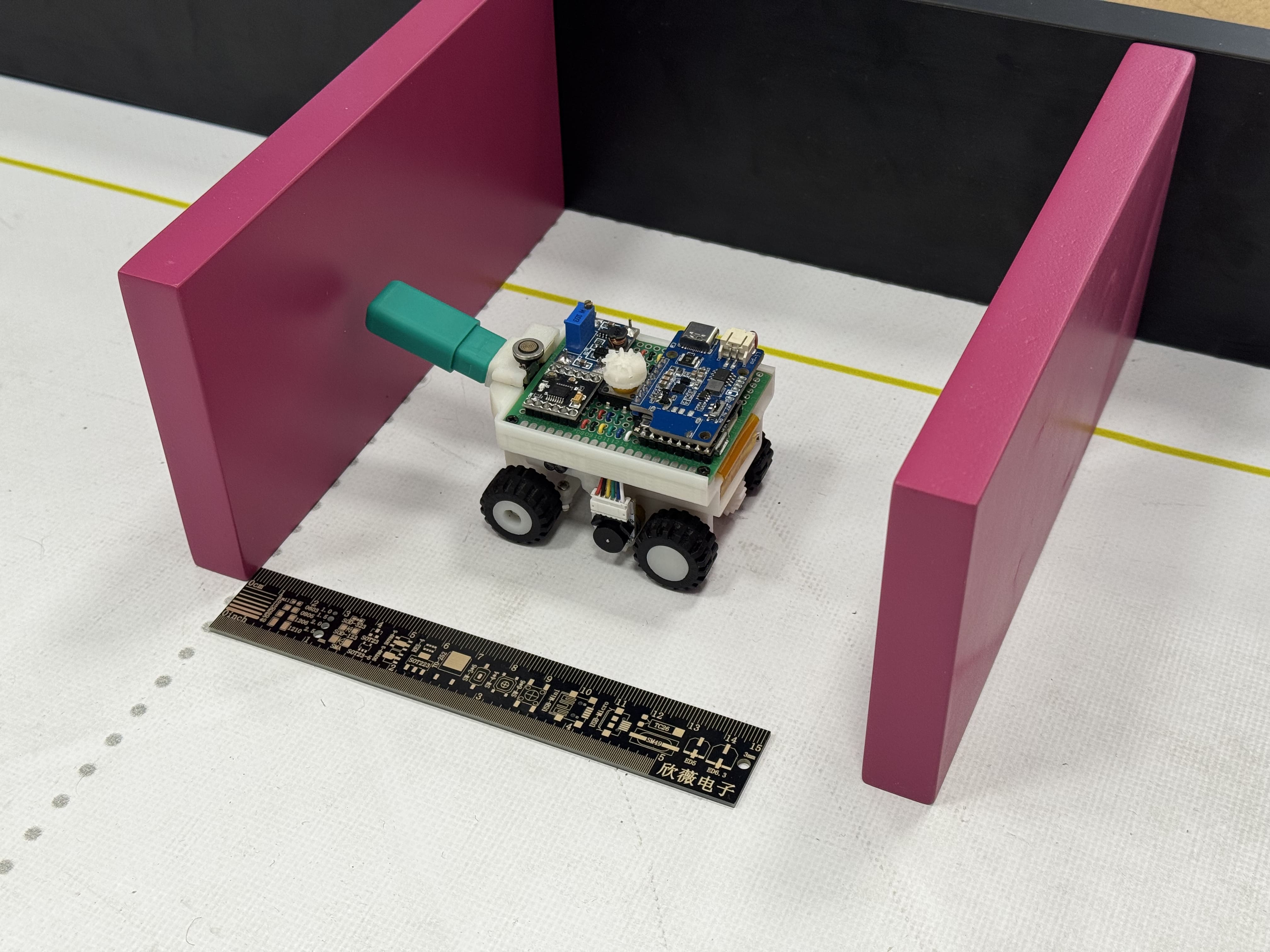
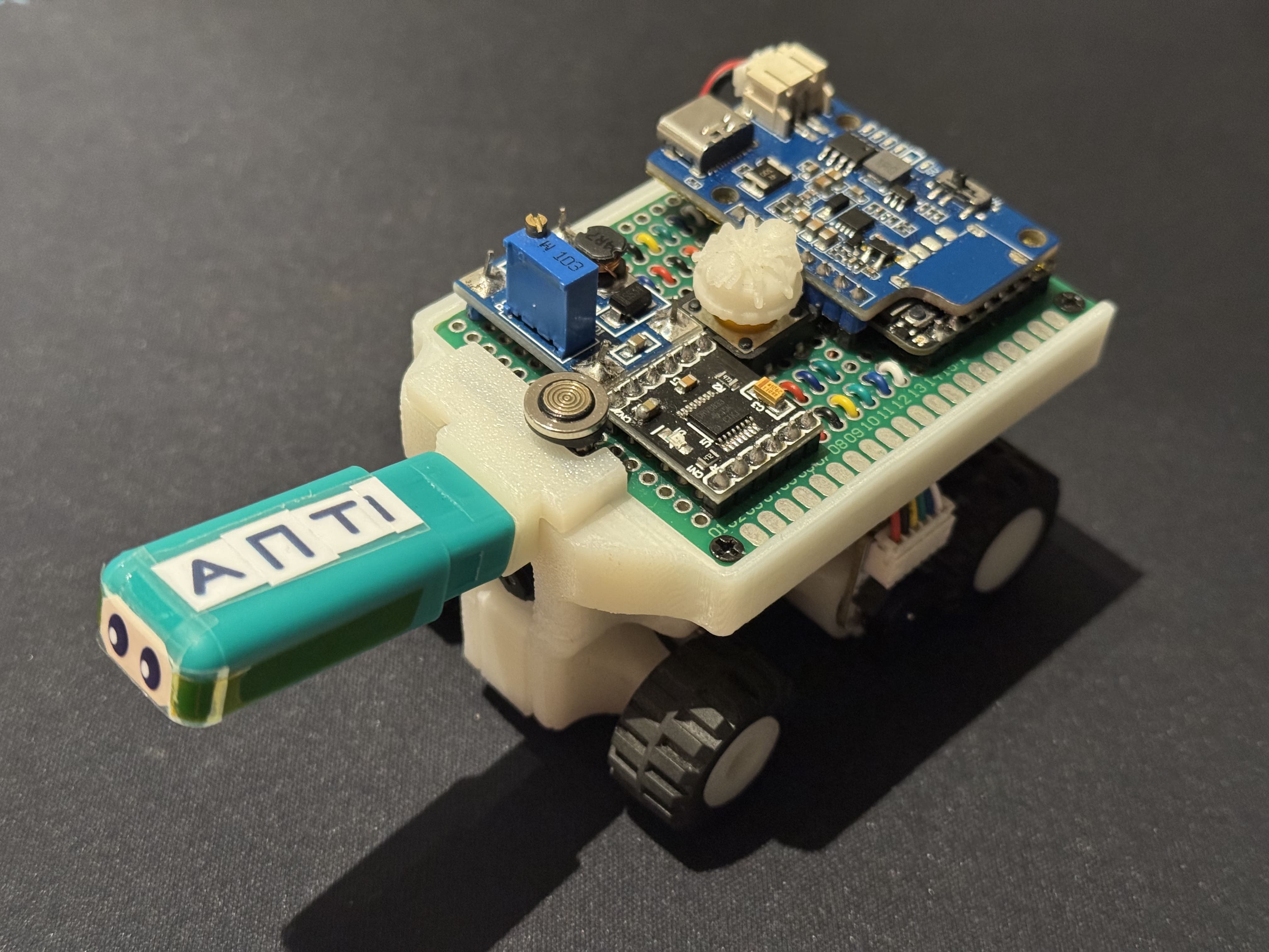
1) Final 110mm vehicle in 165mm parking space with measurement verification • 2) Close-up of refined extension with custom branding and visual enhancements
### Parallel Parking – Potential Improvements
- Pure vision-based parking using parking walls as obstacles → eliminates ToF distance dependency and works even if the parking zone is shifted elsewhere.
- Single-motion slow parking trajectory instead of safer fast three-segment → would save ~1.5 s .
### **Obstacle Navigation Patterns**
The algorithm handles all possible obstacle combinations through systematic pattern recognition and response.
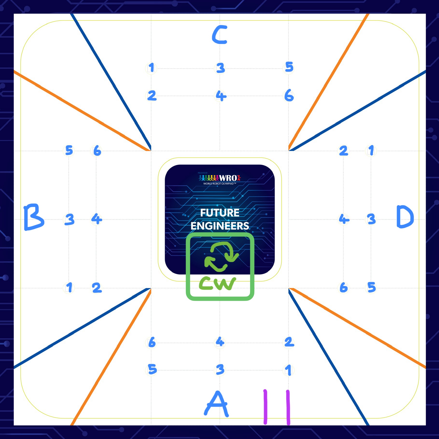
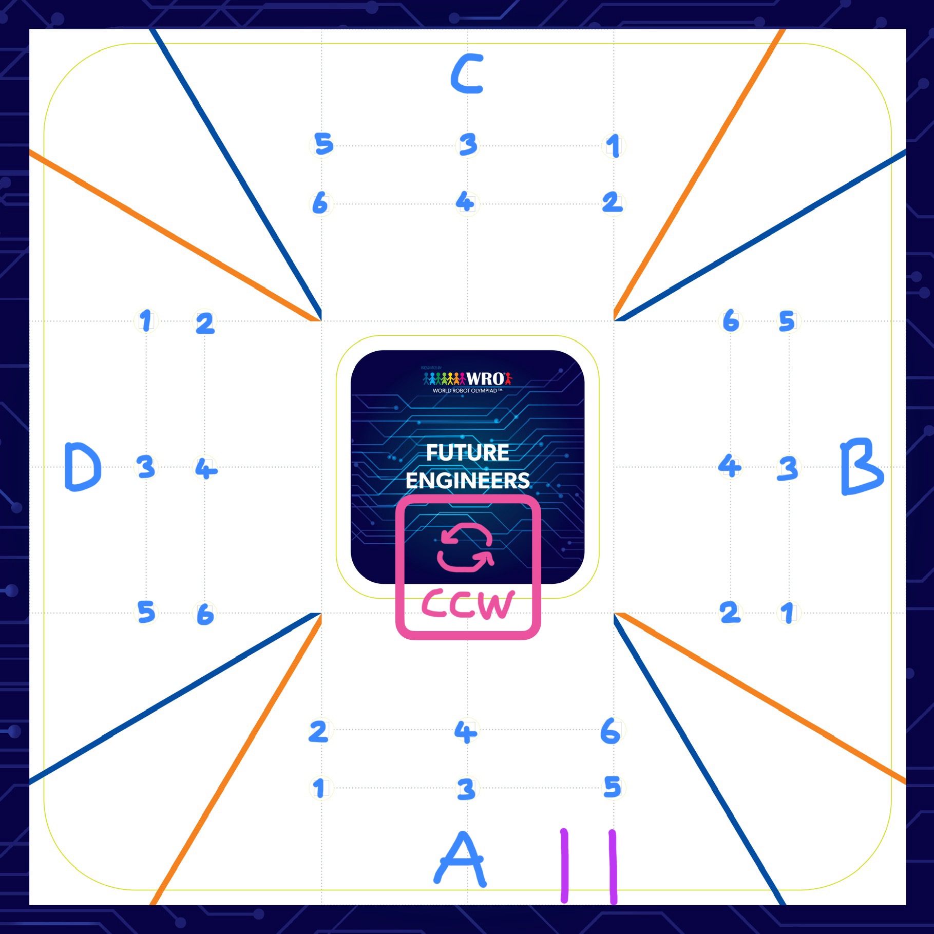
Comprehensive obstacle combination analysis for both navigation directions
### **Vision Processing Pipeline**
1. **Image Capture**: 320×240 resolution at 26 frames per second
2. **Color Transformation**: RGB to LAB colorspace conversion
3. **Feature Detection**: Blob analysis with size and shape filtering
4. **Target Identification**: Largest valid blob selection for reliability
5. **Error Calculation**: Position deviation from desired tracking point
### Software & Algorithms – Potential Improvements
- Replace hand-tuned PID with online adaptive gain scheduling based on lap time → we already have easy possible integration of lap-time logging via the nRF52832.
- Add optical flow (using the GC2145 bottom 80×80 pixels) for dead-reckoning backup when camera loses the line detection.
- Over-the-air firmware update via BLE (nRF52832) → Eliminates the need for cables during competition day, further improving ease of use compared to magnetic connections.
Complete software implementation details available in our [source code documentation](src/README.md).
---
## 📹 **Performance Videos**
Our development process included precise testing and validation to ensure competition-ready performance across both challenge scenarios.
### **Competition Performance**
- **Open Challenge**: 16-second perfect score demonstration
- **Obstacle Challenge**: 35-second perfect score with integrated parking
- **Detection Reliability**: >95% accuracy across variable lighting conditions
- **System Responsiveness**: <50ms latency from detection to actuation
### **Video Documentation**
Complete performance demonstrations showcasing our vehicle's capabilities:
- **Open Challenge**
[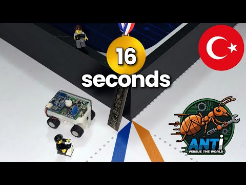](https://youtu.be/tvqgwusap9M)
*Demonstrates autonomous navigation and speed control on a dynamic track.*
- **Obstacle Challenge**
[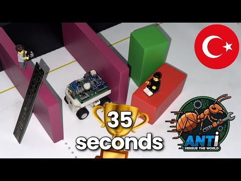](https://youtu.be/fQPjyJrE8p8)
*Shows traffic sign detection, obstacle avoidance, optimal path planning and parallel parking with smooth obstacle following at consistent distances.*
**Media Production**: All logos and visual media edits were created by our team using the ***ibisPaint X*** mobile application. Video overlay commentary and caption explanation edits were also done by our team using ***CapCut*** for professional presentation of our performance videos.
---
## 🌐 **GitHub Utilization & Development**
We leveraged GitHub as our central platform for comprehensive project management, version control, and public documentation, while maintaining a clean and professional repository history through our development workflow: working on local computers directly connected to our repository and committing changes only at significant milestones (e.g., completing the chassis design, integrating the vision system, finalizing obstacle navigation) to avoid disorganized overcommitting.
### **Development Workflow Strategy**
**Structured Development Approach**:
- **Local Development Environment**: Intensive development on local machines with feature branches
- **Milestone-Based Committing**: Strategic commits representing significant technical achievements
- **Quality Assurance**: Thorough testing and documentation before public repository updates
- **Clean Public History**: Professional repository showcasing polished development progression
**File Sharing and Public Updates**: All project assets, CAD files (`models/`), schematics (`schemes/`), source code (`src/`), and GitHub documentation are shared publicly at each milestone. Before pushing updates, we cleaned up our progress, data, and results to ensure the public repository reflects a safer and smoother development process than our local workflow, making it easier for others to understand and replicate. Additionally, we record the date and time of the last updates in the README documents, providing easy access to the commit date and version.
### **Commit History & Project Evolution**
Our development timeline from March to November 2025 demonstrates consistent progress and systematic engineering:
**Key Development Milestones**:
- **March 2025**: Repository initialization and project structure establishment
- **May 2025**: Core mechanical design and electronic system implementation
- **October 2025**: International competition preparation and system optimization
- **November 2025**: Final documentation, performance tuning, and competition readiness
**Commit Philosophy**: Each of our 20+ commits represents substantial technical progress, including:
- Complete mechanical system implementations (`design_base.3mf`, `4_gear_differential.3mf`)
- Electronic schematic and wiring documentation (`wiring_diagram.jpg`)
- Software algorithm development and optimization (`open.py`, `obstacle.py`)
- Comprehensive technical documentation updates across all 8 specialized folders
- Performance validation and testing results with competition videos
### **Repository Organization Excellence**
**Comprehensive Documentation Structure**:
- **8 Specialized Folders**: Each containing detailed technical README documentation
- **Structured File Organization**: Logical grouping of related technical assets
- **Professional Presentation**: Clean, well-organized repository layout
- **Easy Navigation**: Intuitive structure for both technical judges and future developers
### **Supporting Future Development & Replication**
## 🔧 **EASY REPLICATION & FUTURE DEVELOPMENT**
### **Our documentation enables effortless duplication by other teams and developers**
**Replication-Focused Design**:
- **Complete Bill of Materials**: All components clearly specified with datasheet information
- **Step-by-Step Assembly Guides**: Detailed instructions for mechanical and electronic assembly
- **Manufacturing Files**: 3MF format for universal 3D printing compatibility
- **Source Code Availability**: Complete software implementation with detailed comments and explanations
- **Troubleshooting Guidance**: Solutions to common implementation challenges
**Supporting Others and Future Development**: While we do not want others to simply copy our work for private or closed-source use, we intentionally chose the AGPL-3.0 license to ensure that any future developments based on our code, robot design, hardware system, or overall architecture remain open-source. This strong copyleft license guarantees that improvements or adaptations, whether for competition, education, or research, must also be shared with the community. We are inviting others to replicate, modify, or build upon our work. The modular design of our system and detailed documentation make it easy to adapt the robot for different challenges. Contributions and suggestions, such as adding multi-robot coordination or advanced path-planning, are welcome via GitHub issues.
**Future Development Pathways**:
- **Modular Architecture**: Easy component upgrades and system modifications using our socket-based design
- **Comprehensive Documentation**: Every design decision and implementation detail documented
- **Open Source Philosophy**: AGPL-3.0 license ensuring continued community access
- **Educational Focus**: Detailed explanations of engineering principles and design choices
### **GitHub Best Practices Implementation**
**Professional Repository Management**:
- **Regular Updates**: Consistent documentation improvements and technical refinements
- **Quality Standards**: High-quality images, professional diagrams, and clear technical writing
- **Accessibility**: Well-structured content suitable for both technical and non-technical audiences
- **Completeness**: Every aspect of the project thoroughly documented and accessible
**Documentation Excellence Standards**:
- ✅ **Complete Information**: Comprehensive coverage of all technical aspects across 8 specialized folders
- ✅ **Structured Organization**: Logical, easy-to-navigate repository structure with clear documentation hierarchy
- ✅ **Regular Commits**: Meaningful, milestone-based version control demonstrating systematic development
- ✅ **Enhanced Engineering Understanding**: Detailed design rationale and implementation insights exceeding basic requirements
---
## 📜 **License & Replication**
### **Open Source Philosophy for Community Advancement**
**Replication-Focused Documentation**:
- **Complete Technical Transparency**: Every design decision and implementation detail documented
- **Manufacturing Accessibility**: Use of widely available components and custom manufacturing methods
- **Educational Value**: Detailed explanations enabling understanding of engineering principles
- **Future Development**: Clear pathways for system improvements and modifications
This project is licensed under the **GNU Affero General Public License v3.0 (AGPL-3.0)** to promote open collaboration, ensure continued community access to derivative works, facilitate easy replication by future developers and competition teams, and foster ongoing innovation through publicly accessible developments.
```
GNU Affero General Public License v3.0
Copyright (C) 2025 Atakan Ersoy (atakanersoy)
This program is free software: you can redistribute it and/or modify
it under the terms of the GNU Affero General Public License as published
by the Free Software Foundation, either version 3 of the License, or
(at your option) any later version.
This program is distributed in the hope that it will be useful,
but WITHOUT ANY WARRANTY; without even the implied warranty of
MERCHANTABILITY or FITNESS FOR A PARTICULAR PURPOSE. See the
GNU Affero General Public License for more details.
You should have received a copy of the GNU Affero General Public License
along with this program. If not, see .
```
### **Comprehensive Documentation Access**
## 📚 **DETAILED TECHNICAL DOCUMENTATION**
### **Explore our specialized documentation for complete technical details**
- **For mechanical design and 3D models**: [Models Documentation](models/README.md)
- **For electrical schematics and wiring**: [Schemes Documentation](schemes/README.md)
- **For software implementation and algorithms**: [Software Documentation](src/README.md)
- **For competition performance videos**: [Video Documentation](video/README.md)
- **For additional resources and photos**: [Other Documentation](other/README.md)
- **For MATLAB vision tools**: [MATLAB Documentation](matlab/README.md)
- **For team information**: [Team Photos Documentation](t-photos/README.md)
- **For vehicle documentation**: [Vehicle Photos Documentation](v-photos/README.md)
---
## 🎯 **Prepared for International Competition Excellence**
**Team ANTi - *Never Stop Developing Unless We Stop Learning***
### **Comprehensive documentation enabling easy replication and future development**
[](https://www.instagram.com/anti.wro/)
[](https://www.youtube.com/@solipsy.)
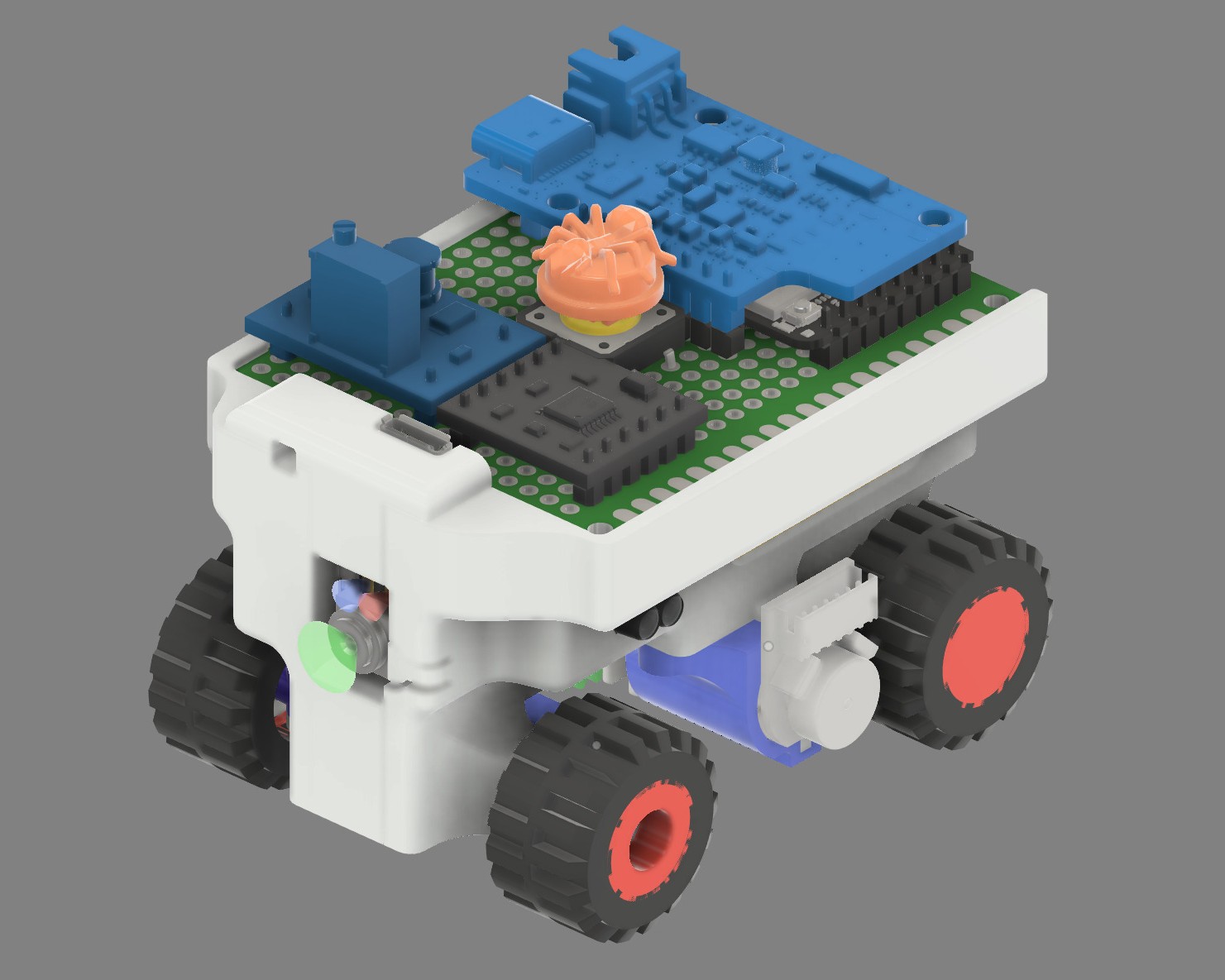
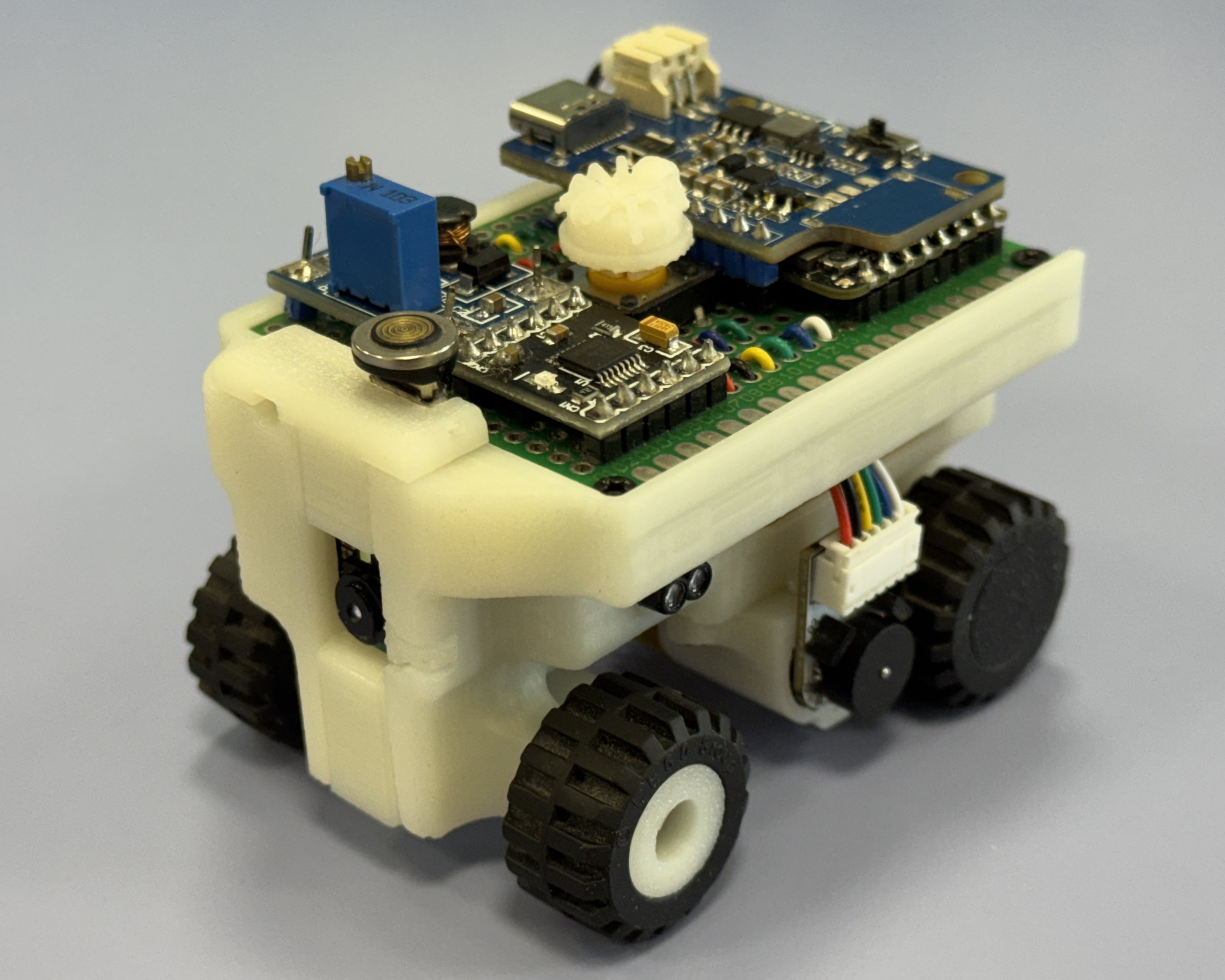
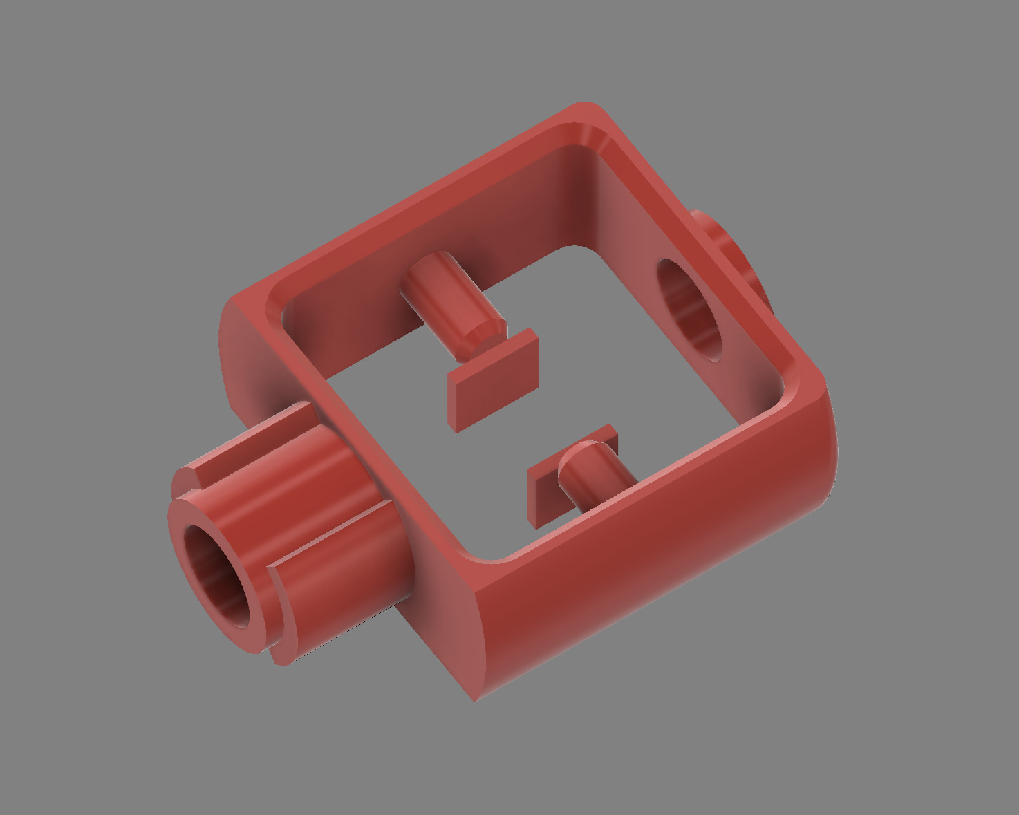
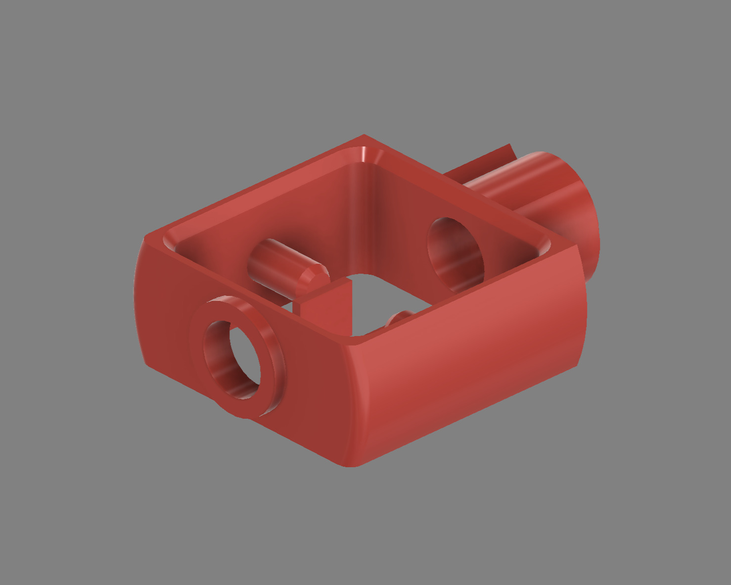
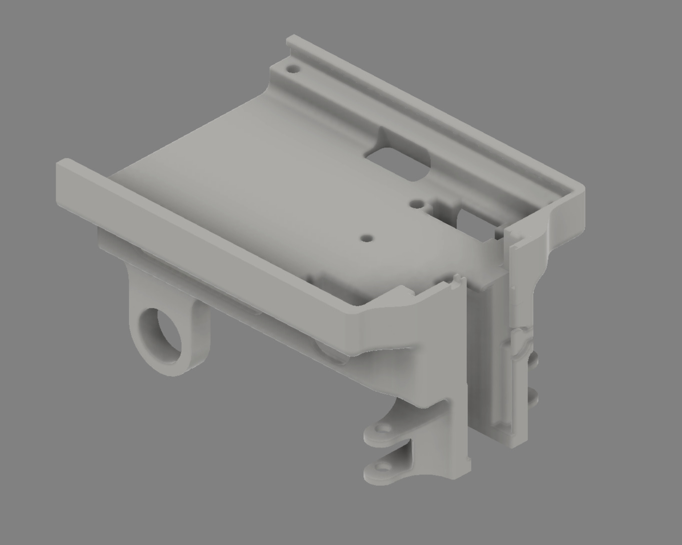
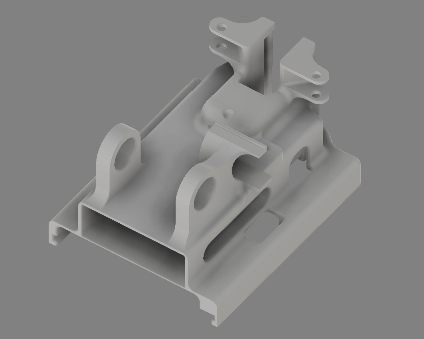 | Primary structural element with integrated mounting features |
| **4-Gear Differential** | [`design_4_gear_mini_differential.3mf`](models/design_4_gear_mini_differential.3mf) | 1 |
| Primary structural element with integrated mounting features |
| **4-Gear Differential** | [`design_4_gear_mini_differential.3mf`](models/design_4_gear_mini_differential.3mf) | 1 | 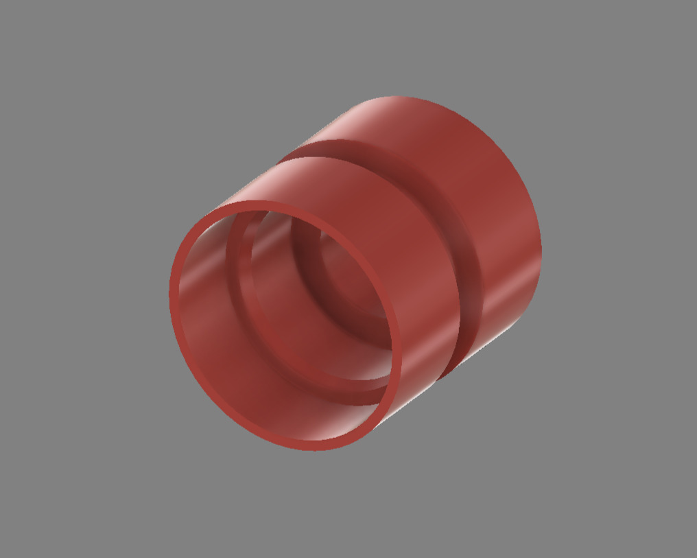
 | Steering wheels with integrated bearing seats |
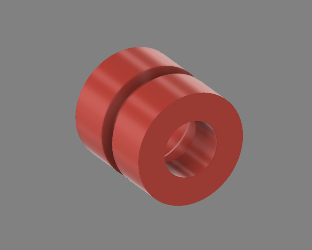
| **Steering Arm** | [`design_steering_arm.3mf`](models/design_steering_arm.3mf) | 2 |
| Steering wheels with integrated bearing seats |
| **Steering Arm** | [`design_steering_arm.3mf`](models/design_steering_arm.3mf) | 2 | 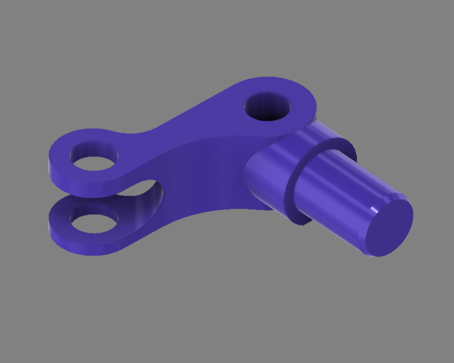
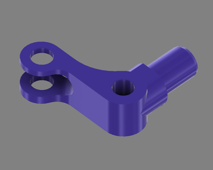 | Ackermann steering linkage arms (left/right pair) |
| **Steering Linkage** | [`design_steering_linkage.3mf`](models/design_steering_linkage.3mf) | 1 |
| Ackermann steering linkage arms (left/right pair) |
| **Steering Linkage** | [`design_steering_linkage.3mf`](models/design_steering_linkage.3mf) | 1 | 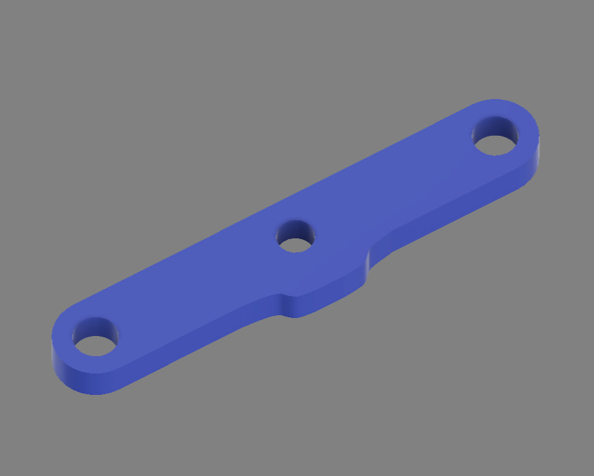 | Central steering connection mechanism |
| **25T Spur Gear** | [`design_spur_25_gear.3mf`](models/design_spur_25_gear.3mf) | 1 |
| Central steering connection mechanism |
| **25T Spur Gear** | [`design_spur_25_gear.3mf`](models/design_spur_25_gear.3mf) | 1 | 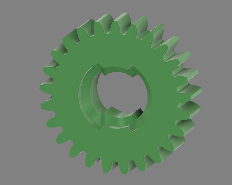
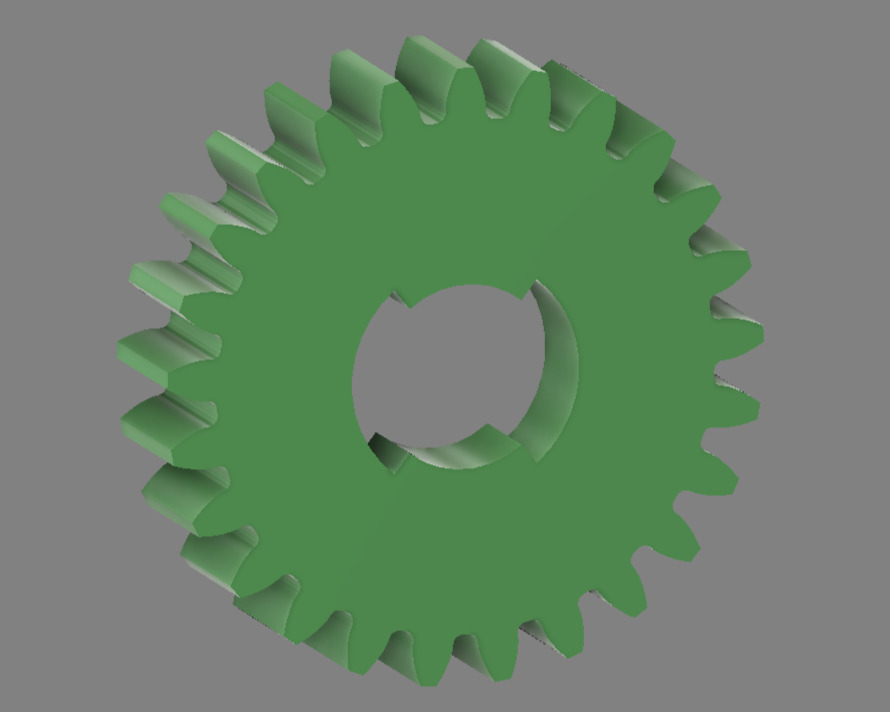 | 25-tooth torque transmission gear |
| **26T Spur Gear** | [`design_spur_26_gear.3mf`](models/design_spur_26_gear.3mf) | 1 |
| 25-tooth torque transmission gear |
| **26T Spur Gear** | [`design_spur_26_gear.3mf`](models/design_spur_26_gear.3mf) | 1 | 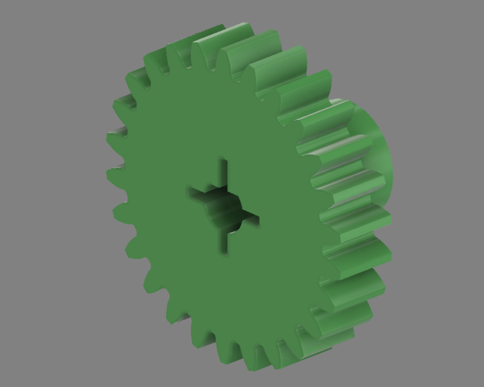
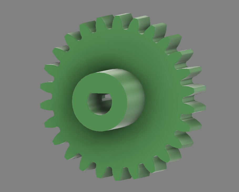 | 26-tooth motor interface gear |
| **12T Bevel Gear** | [`design_bevel_12_gear.3mf`](models/design_bevel_12_gear.3mf) | 4 |
| 26-tooth motor interface gear |
| **12T Bevel Gear** | [`design_bevel_12_gear.3mf`](models/design_bevel_12_gear.3mf) | 4 | 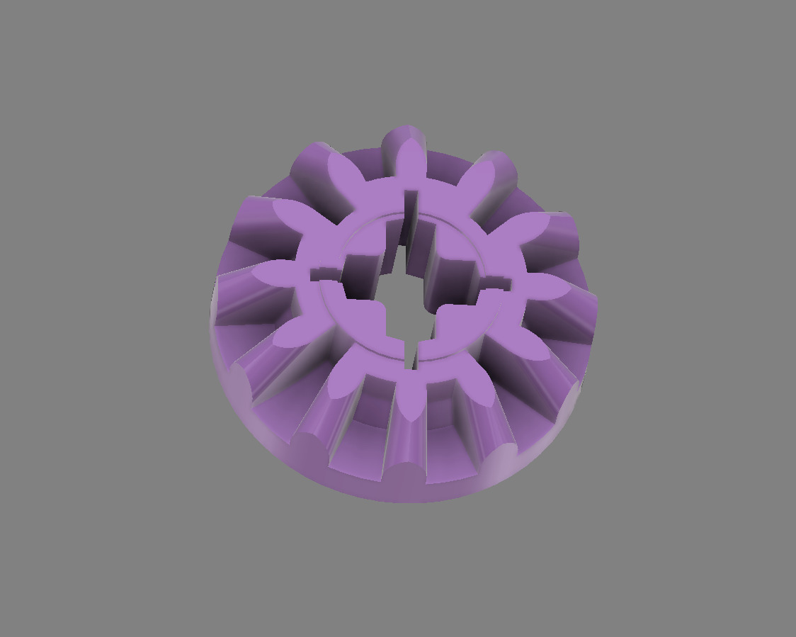
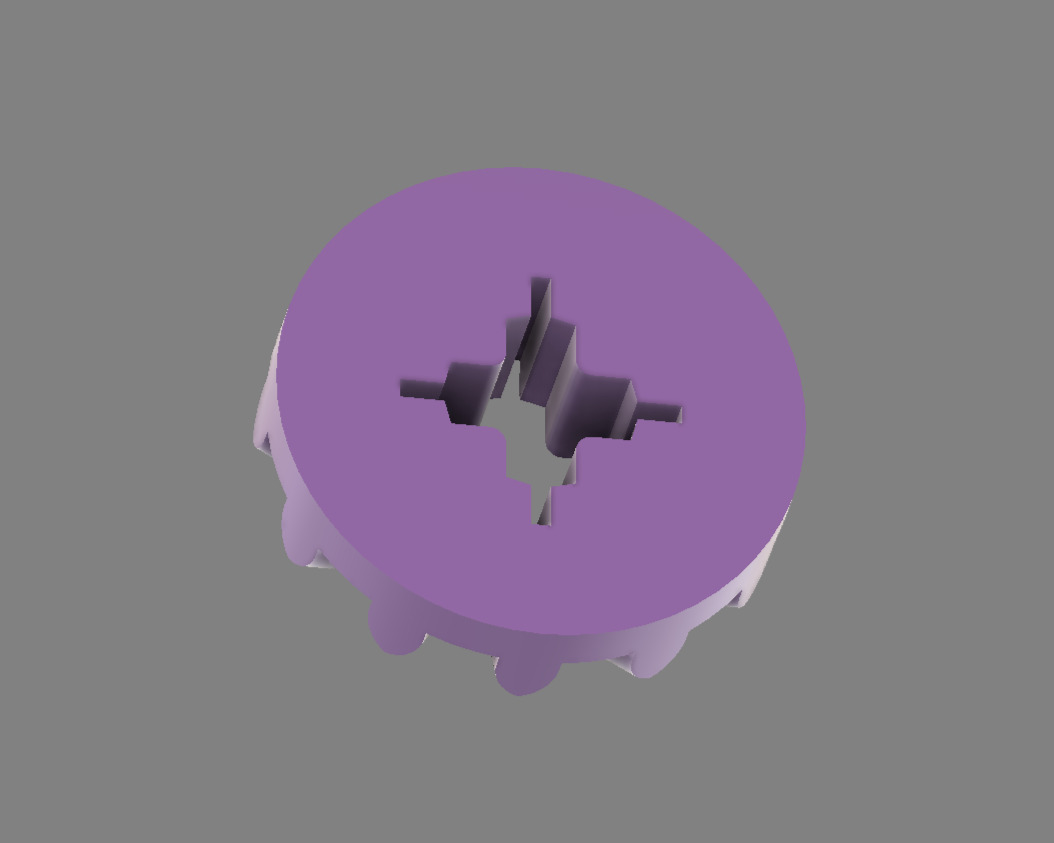 | Differential bevel gears (set of 4 required) |
| **Motor Enclosure** | [`design_motor_lid.3mf`](models/design_motor_lid.3mf) | 1 |
| Differential bevel gears (set of 4 required) |
| **Motor Enclosure** | [`design_motor_lid.3mf`](models/design_motor_lid.3mf) | 1 | 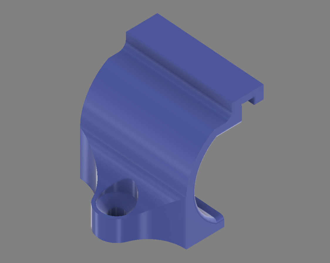 | N20 motor protective housing |
| **Long Rear Rim** | [`design_back_rim_long.3mf`](models/design_back_rim_long.3mf) | 1 |
| N20 motor protective housing |
| **Long Rear Rim** | [`design_back_rim_long.3mf`](models/design_back_rim_long.3mf) | 1 | 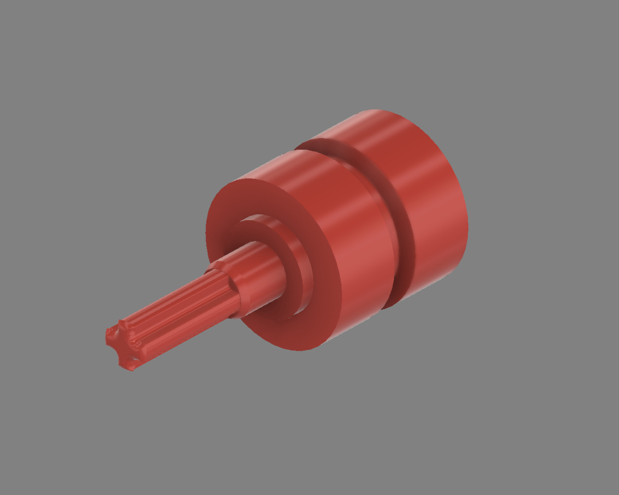 | Extended right-side drive wheel |
| **Short Rear Rim** | [`design_back_rim_short.3mf`](models/design_back_rim_short.3mf) | 1 |
| Extended right-side drive wheel |
| **Short Rear Rim** | [`design_back_rim_short.3mf`](models/design_back_rim_short.3mf) | 1 | 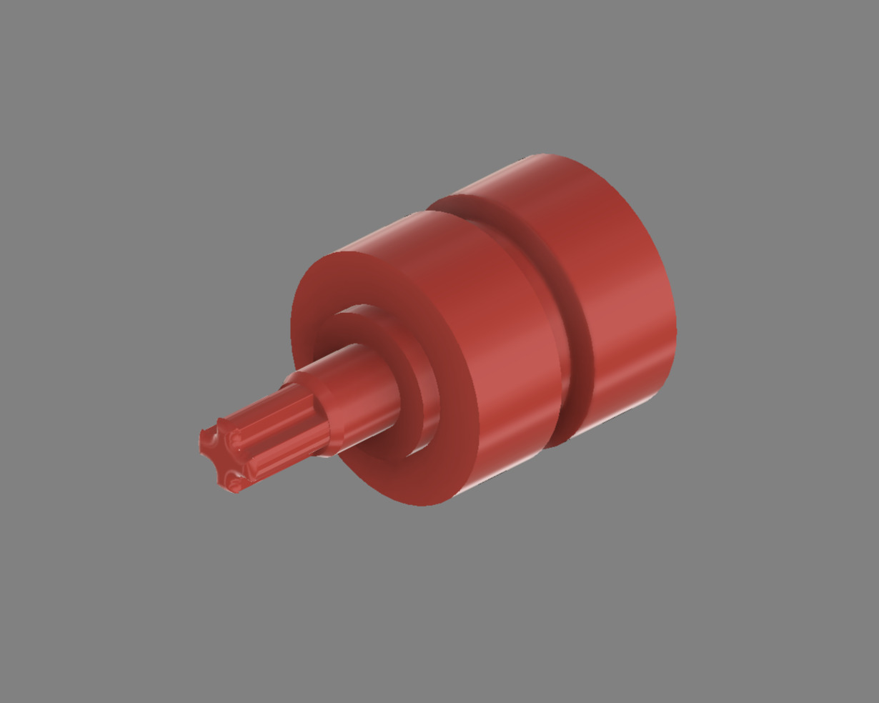 | Compact left-side drive wheel |
| **Front Upper Cover** | [`design_front_top_cover.3mf`](models/design_front_top_cover.3mf) | 1 |
| Compact left-side drive wheel |
| **Front Upper Cover** | [`design_front_top_cover.3mf`](models/design_front_top_cover.3mf) | 1 | 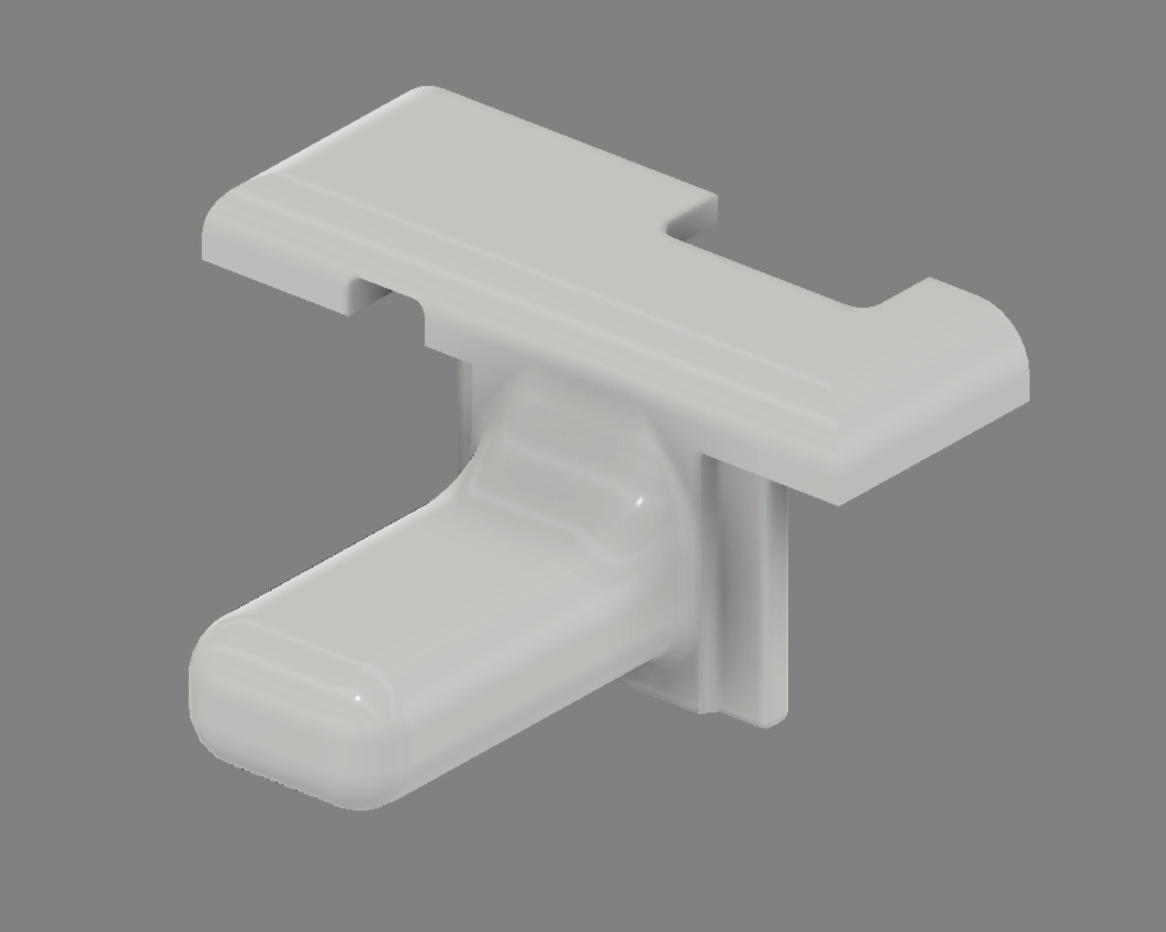
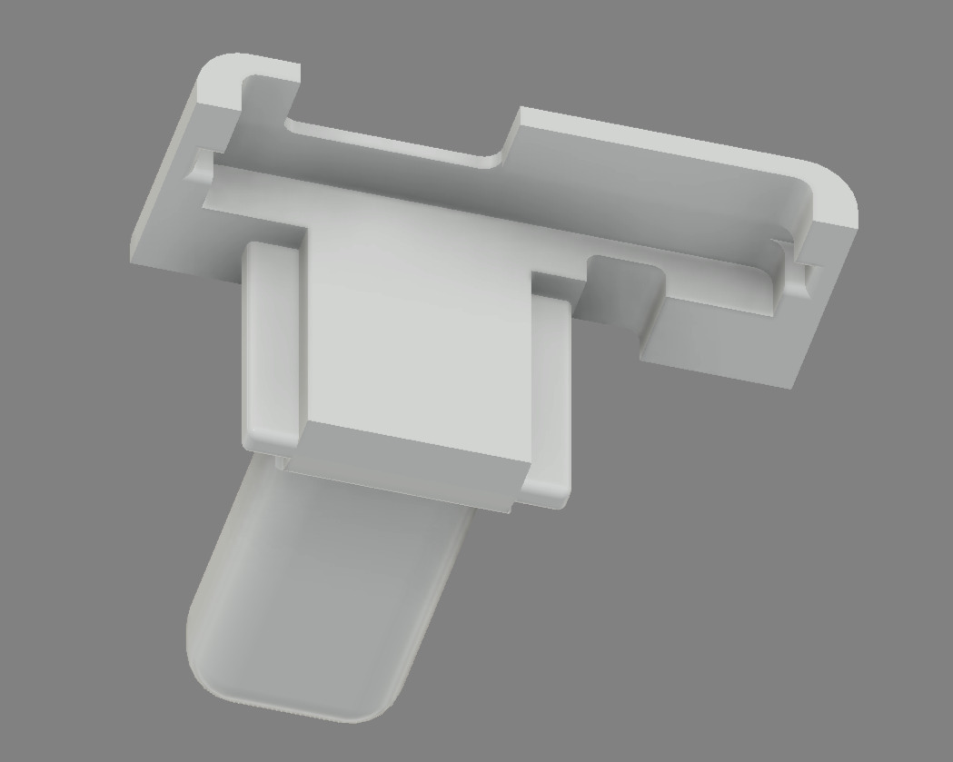 | Electronics protection shield |
| **Front Lower Cover** | [`design_front_bottom_cover.3mf`](models/design_front_bottom_cover.3mf) | 1 |
| Electronics protection shield |
| **Front Lower Cover** | [`design_front_bottom_cover.3mf`](models/design_front_bottom_cover.3mf) | 1 | 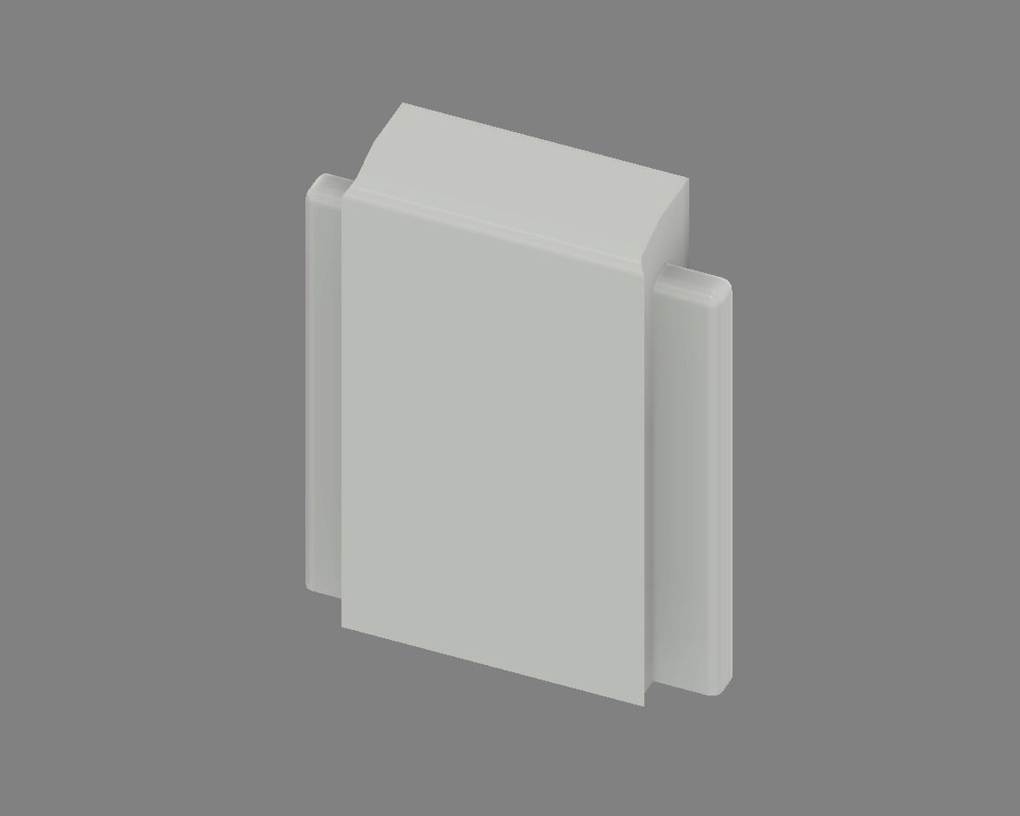 | Underbody protection panel |
| **Button Interface** | [`design_button_cap.3mf`](models/design_button_cap.3mf) | 1 |
| Underbody protection panel |
| **Button Interface** | [`design_button_cap.3mf`](models/design_button_cap.3mf) | 1 | 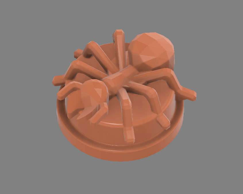
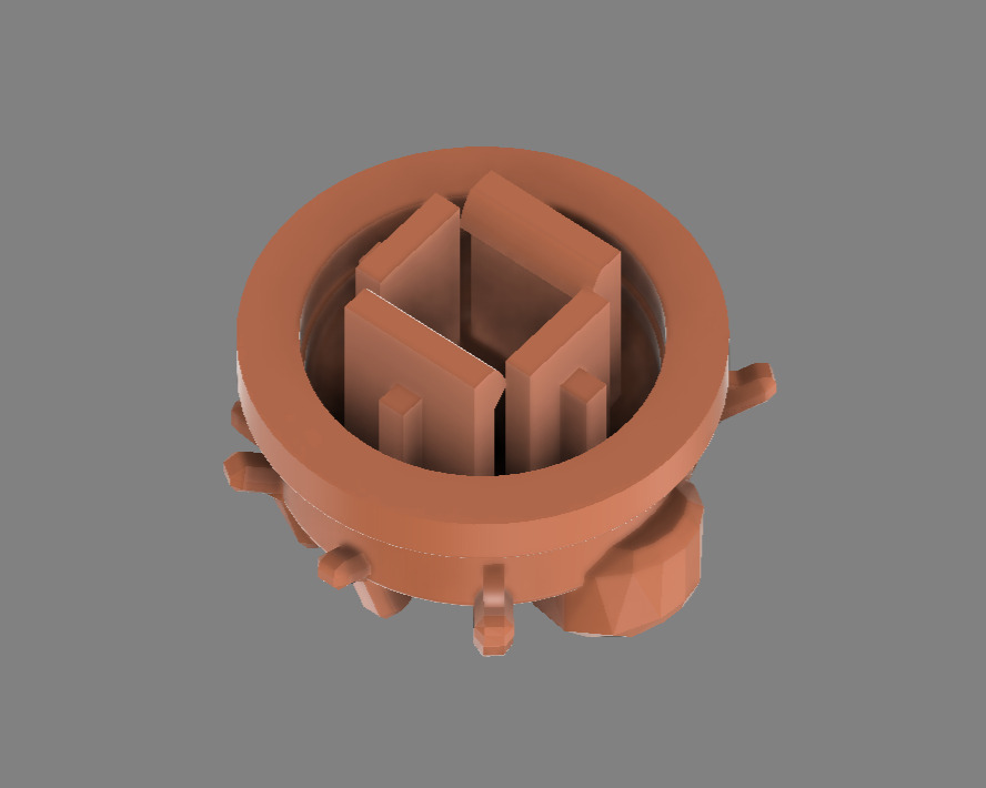 | User interface button cap |