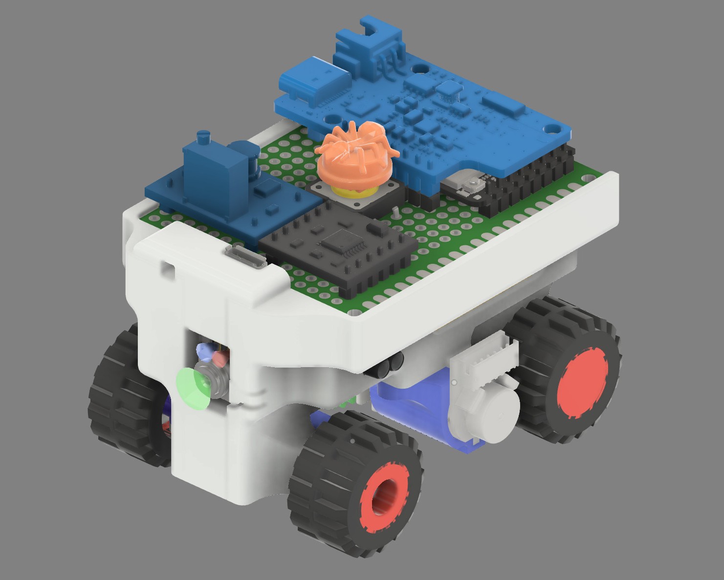
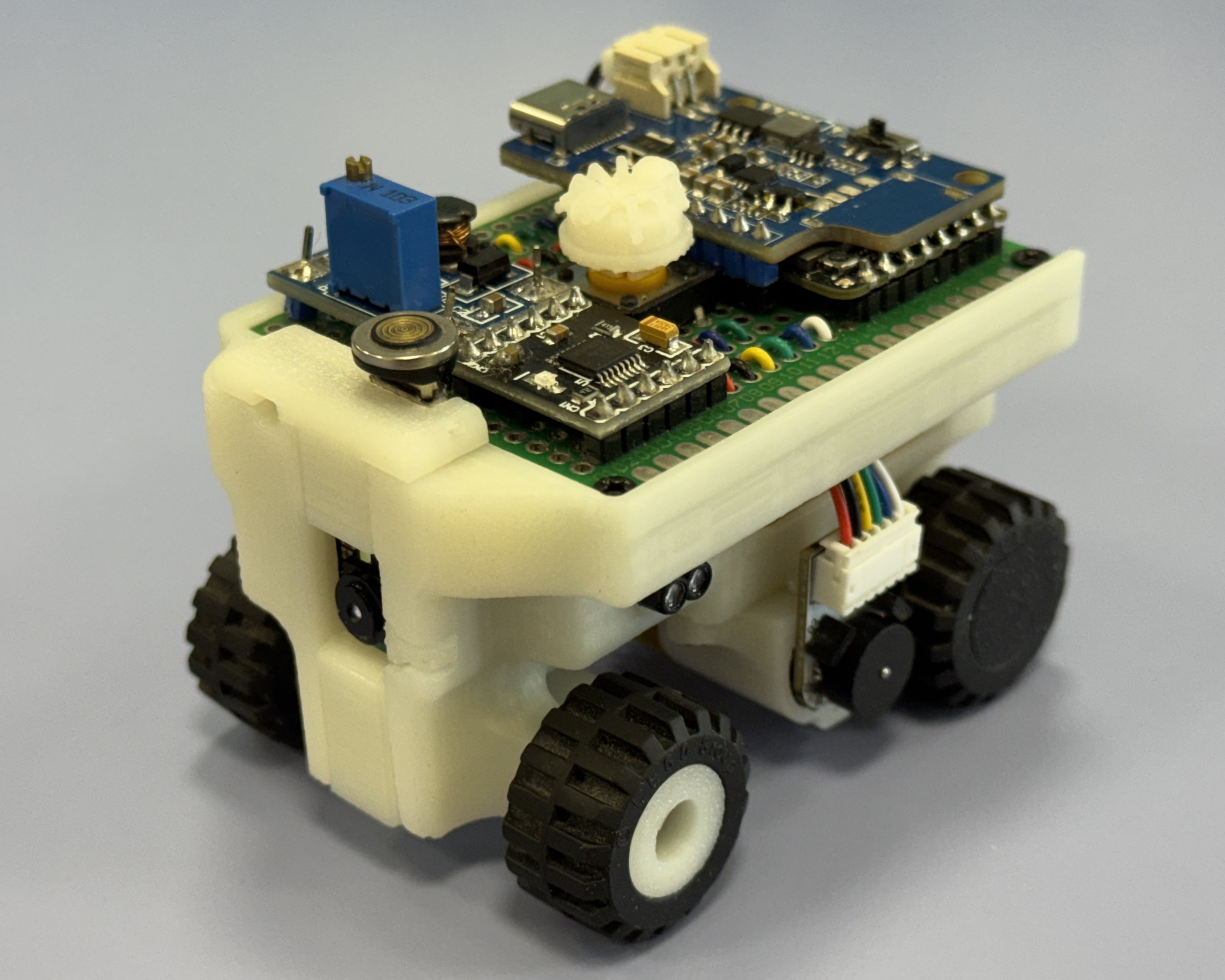
Direct comparison: 1) CAD design visualization vs 2) physical implementation from identical isometric perspectives
## ⚙️ Core Mechanical Systems ### 🔄 Custom Ackermann Steering Geometry The steering system implements true Ackermann principles where each wheel points toward a common center point during turns, minimizing tire scrub and maximizing stability.
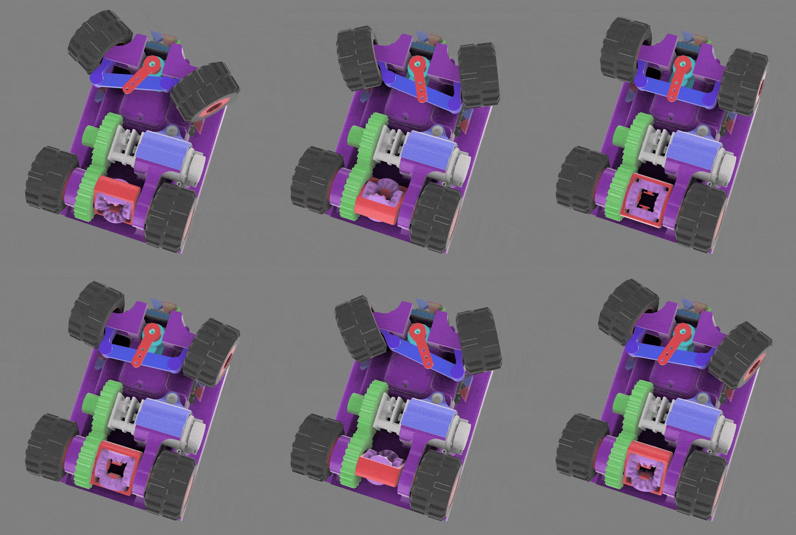
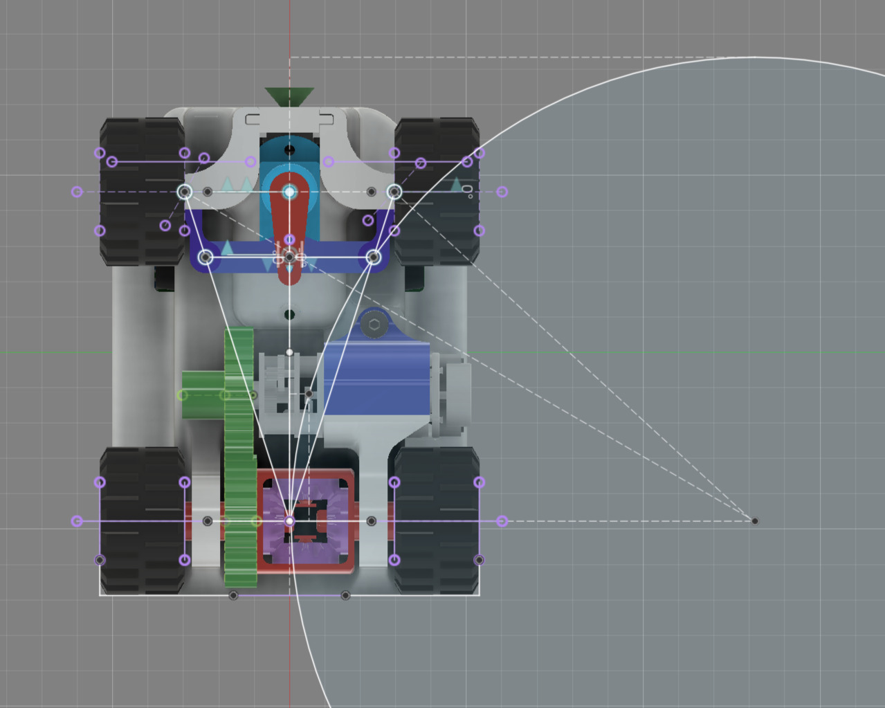
1) Real-time CAD simulation demonstrating steering mechanism operation • 2) Engineering calculations showing Ackermann geometry and optimal turning radius
Higher quality video: 3d_CAD_motion.mp4
|
|
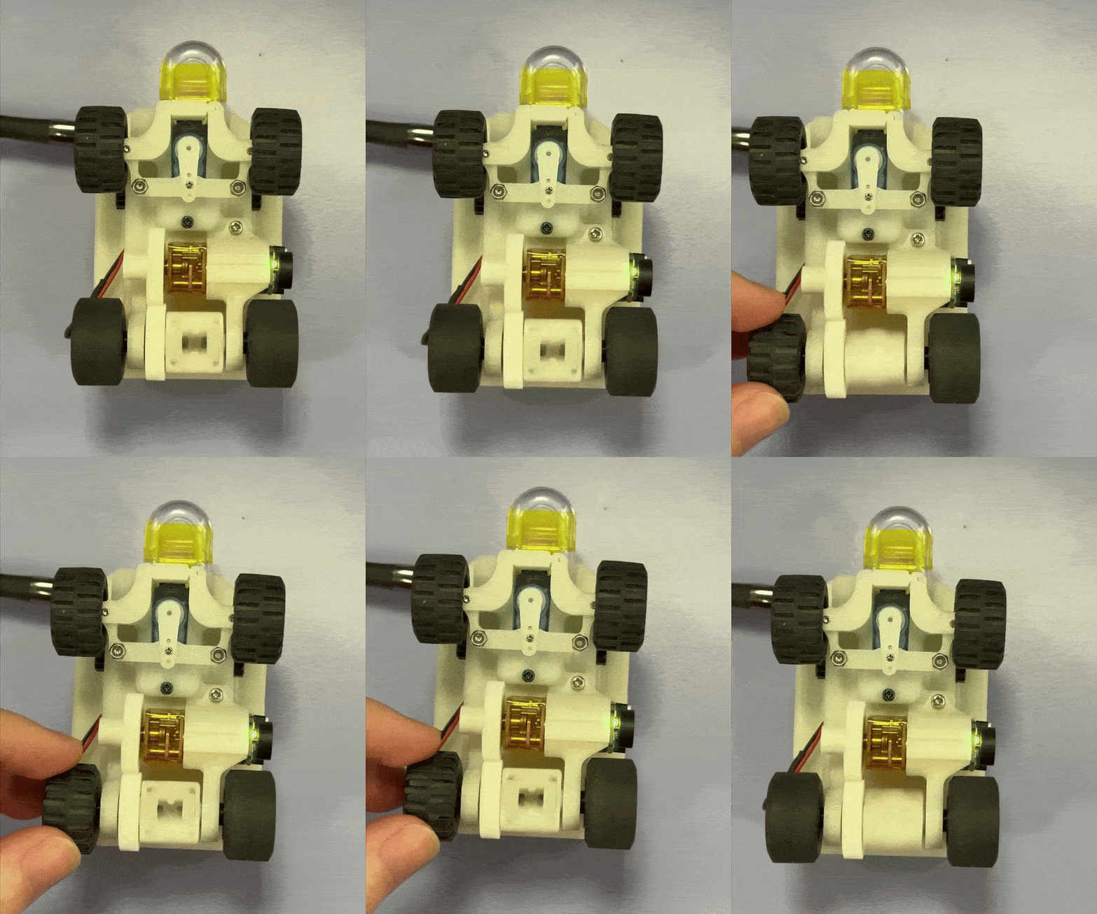
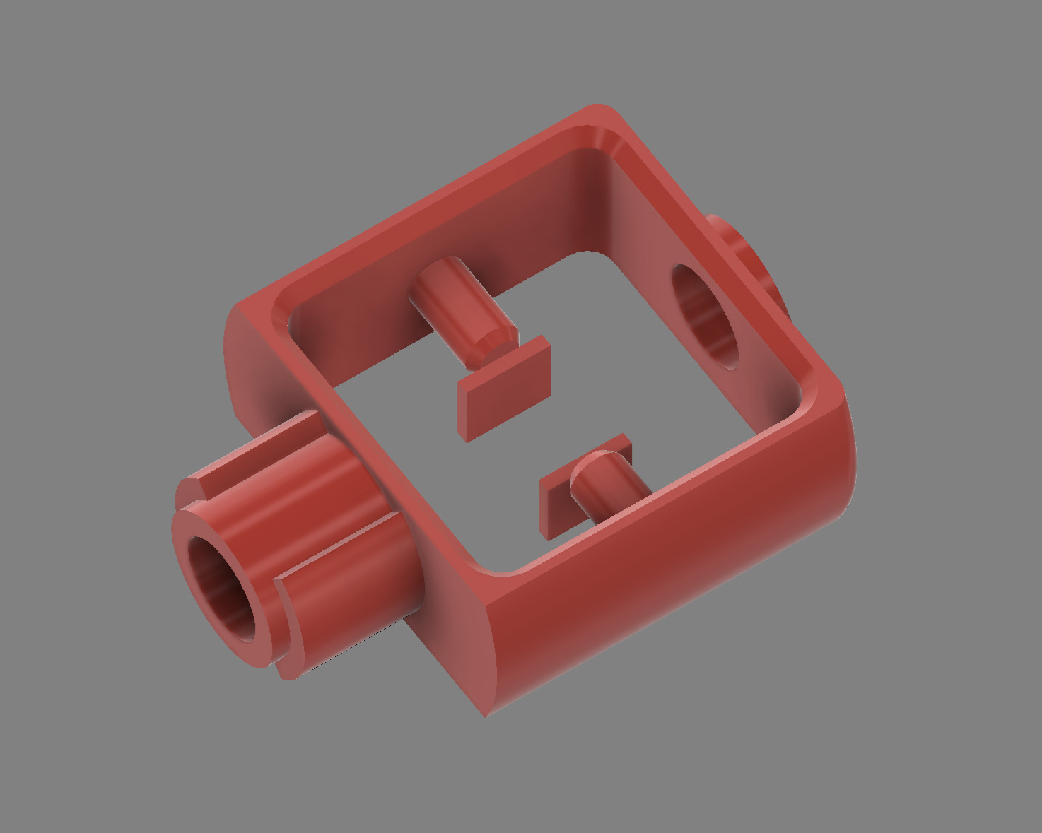
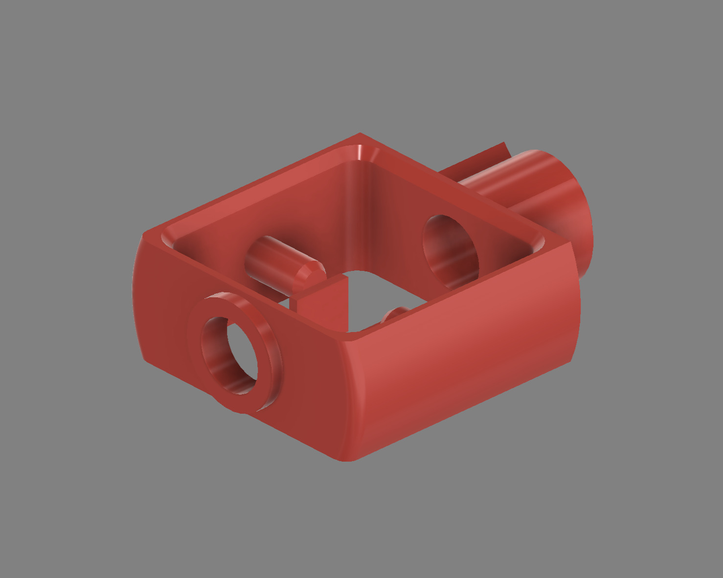
1) Physical differential test demonstrating independent wheel rotation • 2) CAD views showing 4-gear differential assembly from multiple angles
Higher quality video: differential_test.mp4
|
|
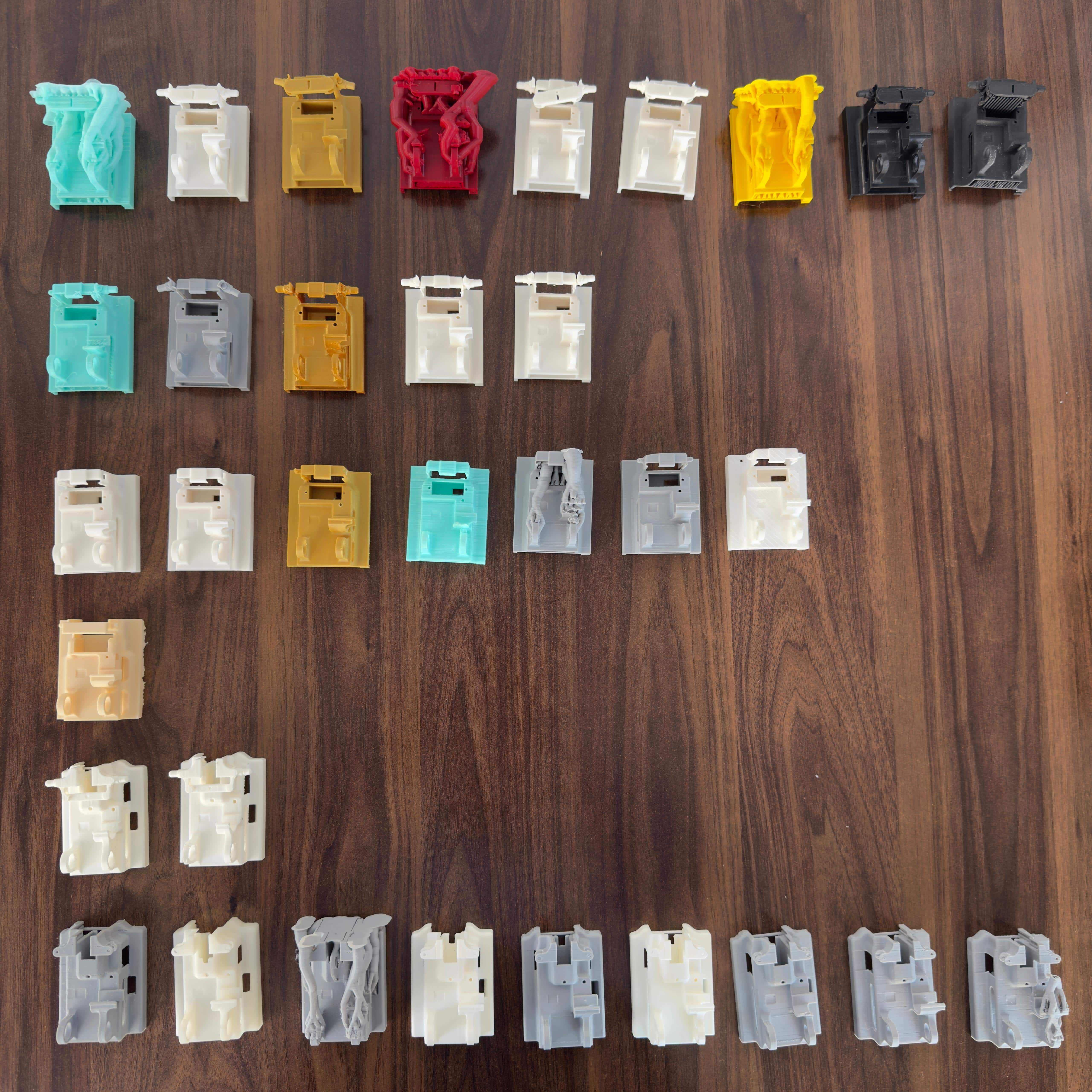
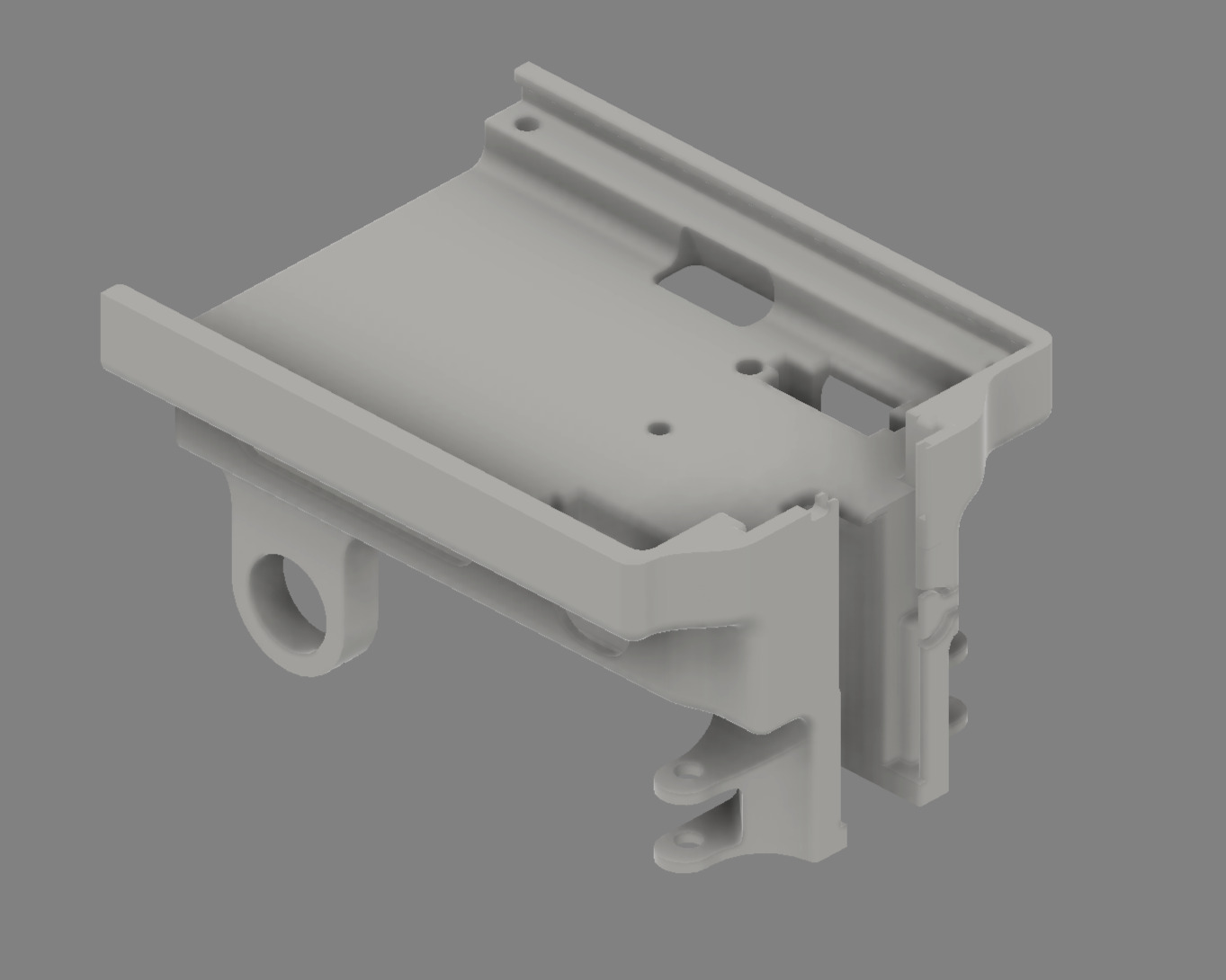
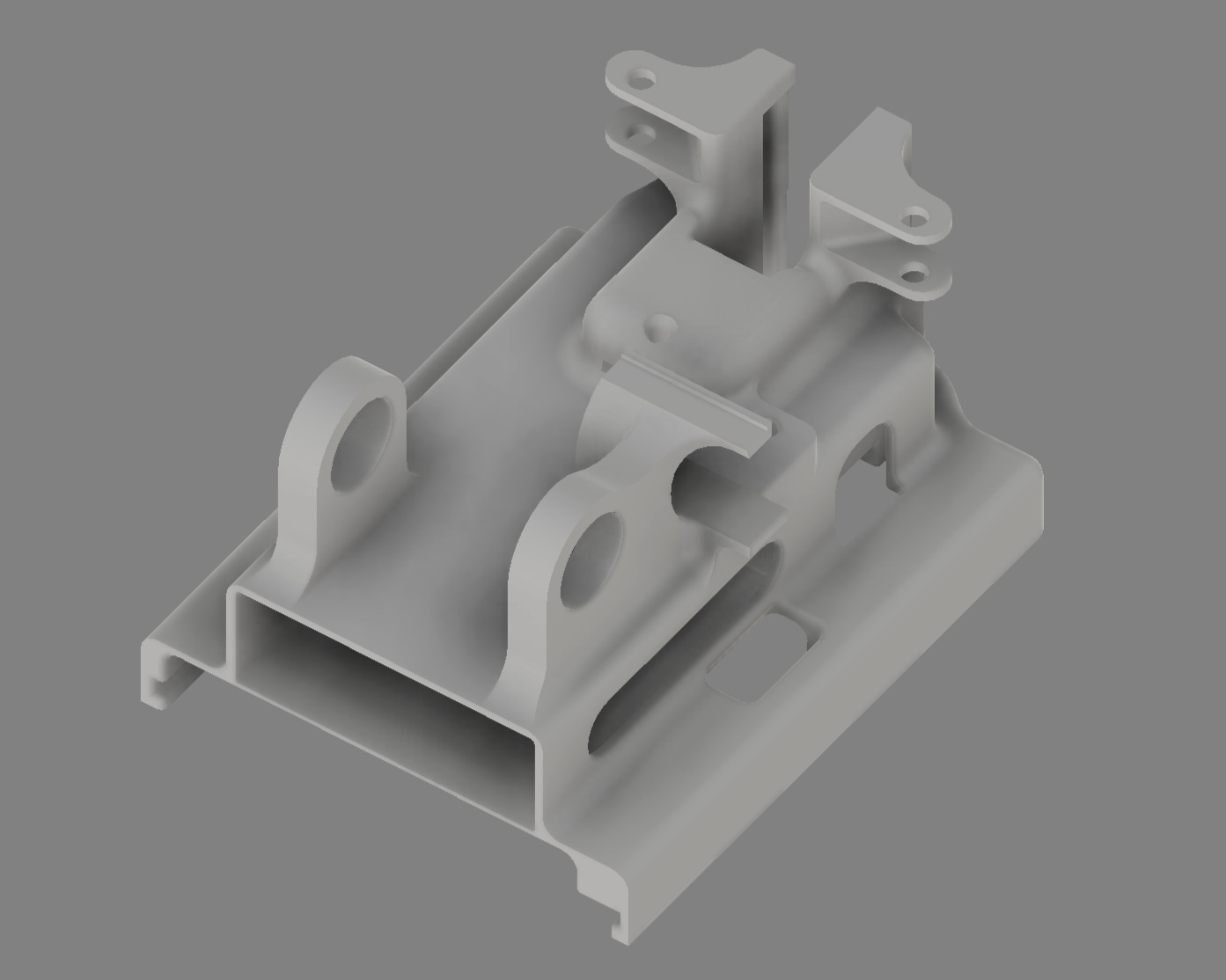
1) Extensive chassis design evolution through multiple iterations • 2) CAD views showing main chassis structure from different perspectives
**Structural Engineering Elements:** - **Integrated Component Mounting System**: Precision slots and holders for pertinax boards, servo, motor, and battery - **Optimized Weight Distribution**: Strategic mass placement ensuring stable navigation and quick response - **Bearing Integration**: Four precision bearings (one per wheel) for smooth rotation with minimal friction - **Access and Maintenance Design**: Strategic openings enabling easy component replacement and field adjustments ## 🏭 Manufacturing Process & Engineering Solutions ### 🖨️ 3D Printing Equipment & Material Strategy We conducted extensive testing across multiple printing technologies in our university makerspace to achieve optimal results. **CAD & Slicing Software Integration**: - **Design Platform**: ***Autodesk Fusion*** for comprehensive 3D modeling, simulation, and engineering analysis - **Slicing Software**: ***Creality Print 6.3*** for optimized print preparation and manufacturing parameter management - **Workflow Integration**: Seamless transition from CAD design to manufacturing-ready 3MF files
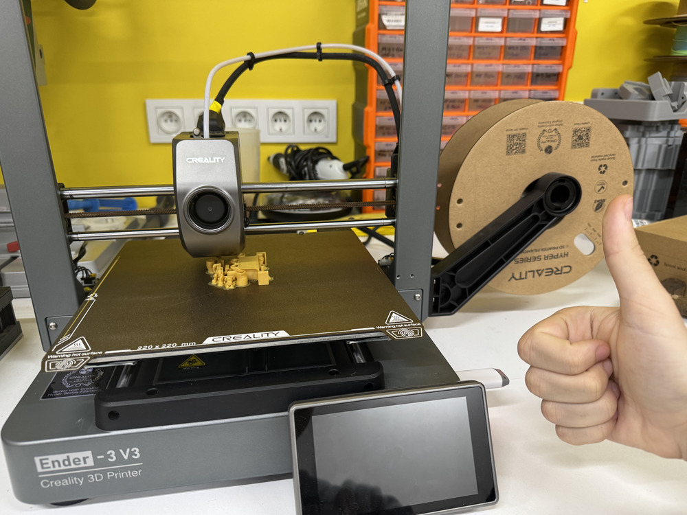
Ender 3v3 printer in operation - our primary manufacturing equipment
**Printing Equipment Evaluation:** | Printer | Technology | Primary Usage | Materials Tested | Key Findings | |---------|------------|---------------|------------------|--------------| | **Ender 3v3** | FDM (Fused Deposition Modeling) | Final production | Hyper ABS, ABS+ | **Optimal Choice** - Reliable performance with ABS materials | | **Zaxe Z3S** | FDM (Fused Deposition Modeling) | Development phase | PLA, ABS | Excellent precision and reliability | | **Bambu Lab A1** | FDM (Fused Deposition Modeling) | Rapid prototyping | PLA | Exceptional speed for design iterations | | **Markforged Mark Two** | CFR (Continuous Fiber Reinforcement) | Advanced testing | Onyx (Nylon+CF) | Limited by proprietary Eiger software constraints | | **Formlabs Form 3B+/3+** | SLA (Stereolithography) | Detail testing | SLA Resins | Superior detail but insufficient impact strength and resin alternatives| ### 🛠️ Comprehensive Material Selection Process **Final Material: Hyper ABS from Creality** Selected for superior layer adhesion, impact resistance, and thermal stability required for competition conditions. **Material Testing Results & Rationale:** - ✅ **FDM - Hyper ABS (Production Choice)**: Optimal strength-to-weight ratio, excellent layer bonding, competition-ready durability - ✅ **FDM - ABS+ (Development Phase)**: Good performance used during national tournament - ❌ **FDM - PLA**: Adequate for initial prototyping but insufficient impact resistance for competition use - ❌ **FDM - PETG**: Challenging dimensional accuracy and stringing issues affecting gear performance - ❌ **SLA - Resin**: Exceptional detail resolution but too brittle for structural components under stress, plus limited availability for reproduction - ❌ **CFR - Onyx (Nylon+CF)**: Exceptional strength but limited by proprietary software preventing custom support optimization and challenging reproducibility **Selection Philosophy**: Chosen materials prioritize **accessibility** and **reproducibility** alongside performance, ensuring other teams can easily replicate our design using commonly available FDM technology rather than specialized industrial equipment. **Technology Overview:** - **FDM (Fused Deposition Modeling)**: Material extrusion through heated nozzle, ideal for functional parts - **SLA (Stereolithography)**: UV laser curing liquid resin, excellent for high-detail prototypes - **CFR (Continuous Fiber Reinforcement)**: Composite printing with continuous fiber strands for maximum strength ### 🔥 Engineering Challenge: ABS Printing Without Dedicated Enclosure **Problem Identification**: Printing ABS material on Ender 3v3 without dedicated heated enclosure caused warping and layer separation issues. **Innovative Solution**: Developed room-scale thermal management system using the entire workspace as a controlled environment. **Thermal Management Process:** 1. **Environmental Pre-conditioning**: Maintain ambient temperature at 28-32°C throughout printing process 2. **Stable Printing Execution**: Complete ABS printing with consistent thermal environment minimizing thermal gradients 3. **Controlled Gradual Cooling**: Allow natural cooling with minimal ventilation to prevent rapid temperature changes 4. **Stabilized Part Extraction**: Remove finished components only after complete thermal stabilization 5. **Process Repeatability**: Continue manufacturing sequence using identical thermal management for consistency **Optimized Printing Parameters:** - **Layer Resolution**: 0.08mm–0.1mm for dimensional accuracy and surface finish - **Infill Strategy**: 30-40% for structural chassis components, 100% for gears and high-stress elements - **Temperature Control**: Nozzle 250-260°C, Bed 80-85°C for optimal layer adhesion - **Nozzle Configuration**: 0.4mm standard nozzle (available equipment) - **Support Strategy**: Tree supports preferred for optimal material usage and clean removal **Advanced Speed Settings:** - **Print Speeds**: Outer wall 200 mm/s, Inner walls 300 mm/s, Sparse infill 200 mm/s - **Specialized Settings**: Top surface 200 mm/s, Gap infill 200 mm/s, Support 150 mm/s - **Quality Optimization**: Support interface 80 mm/s, First layer 60 mm/s - **Travel & Overhangs**: Travel speed 500 mm/s, Overhang reduction 30-20-10% - **Bridge Control**: External bridges 25 mm/s, Internal bridges 160 mm/s ### 📁 3MF File Format Advantage **Why 3MF for Maximum Reproducibility:** - **Universal Compatibility**: Works across all printer brands and slicing software, unlike machine-specific G-code - **Complete Scene Preservation**: All print settings, orientations, and arrangements embedded - **Advanced Feature Support**: Custom support placements, support settings, and manual modifications preserved - **Color & Material Information**: Visual specifications maintained for consistent results - **Exact Alignment**: Bed positioning and part orientation preserved for identical outcomes - **One-Click Manufacturing**: Direct import with all manufacturing parameters intact for perfect reproduction ## 🧩 Comprehensive Assembly Guide ### 📋 Detailed Step-by-Step Assembly Process
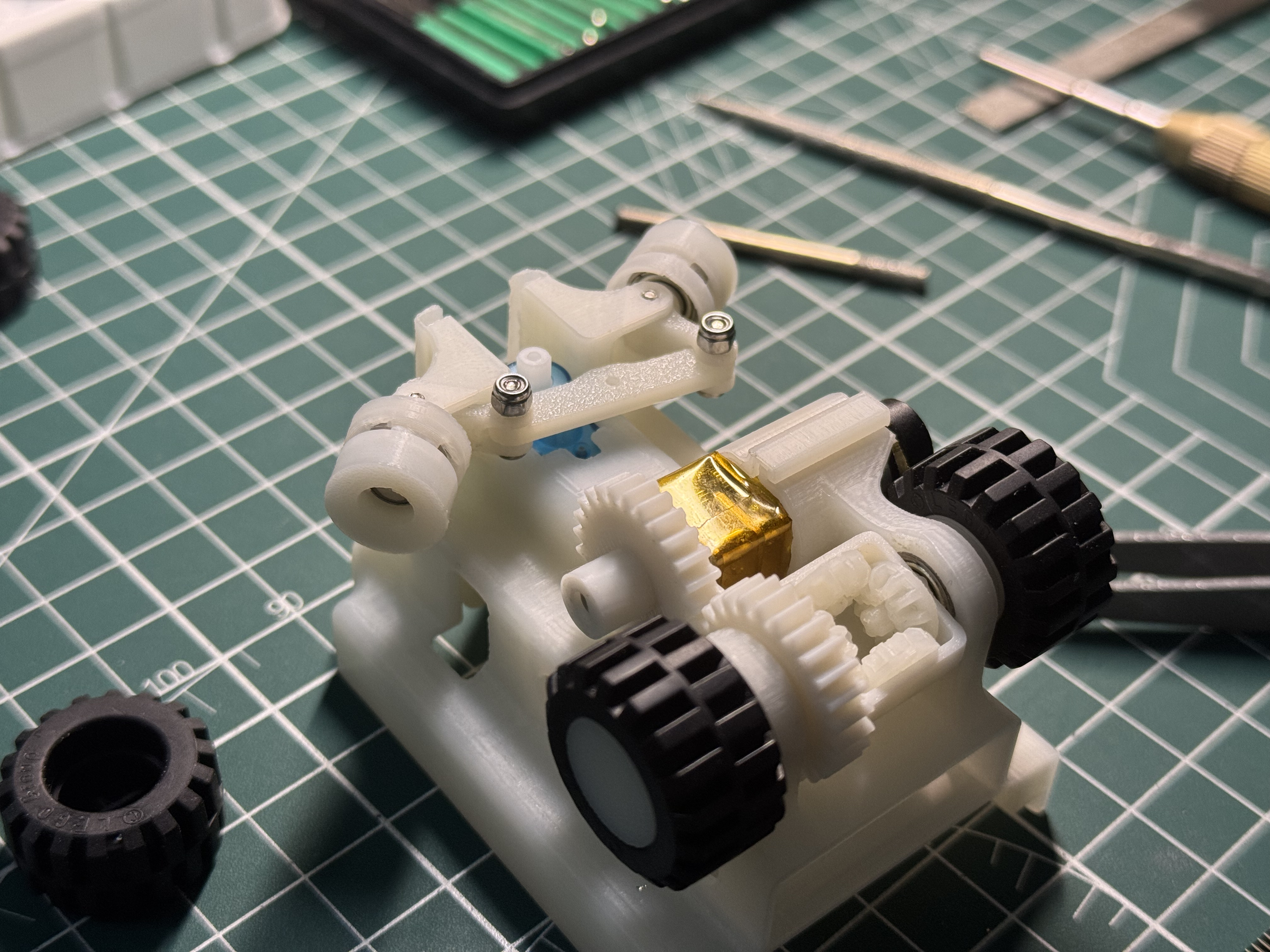
Intermediate assembly stage showing mechanical systems integration and component relationships
**Phase 1: Drive Train Assembly & Power Transmission** 1. **Differential System Installation**: Precision alignment of 4-gear mechanism ensuring smooth power transfer 2. **Motor Integration**: Secure mounting of 1500 RPM N20 motor with custom enclosure using M2 hardware 3. **Gear Meshing Verification**: Ensure proper engagement of 25T and 26T spur gears with optimal backlash **Phase 2: Steering System Integration & Control** 1. **Ackermann Mechanism Assembly**: Install steering arms and linkage with 4 M2 screws and 2 M2 lock nuts 2. **Servo Integration**: Connect Feetech FS0307 servo to steering mechanism with precise alignment 3. **Front Wheel System**: Install bearings and front rims ensuring smooth rotation and minimal play **Phase 3: Chassis Completion & System Integration** 1. **Electronic Platform Mounting**: Secure pertinax boards with all electronic systems in designated slots 2. **Power System Installation**: Mount Power-Xtra LiPo battery in optimized weight distribution position 3. **Final Mechanical Validation**: Comprehensive check of all systems for optimal performance and reliability ## 🔄 Component Development & Engineering Iteration
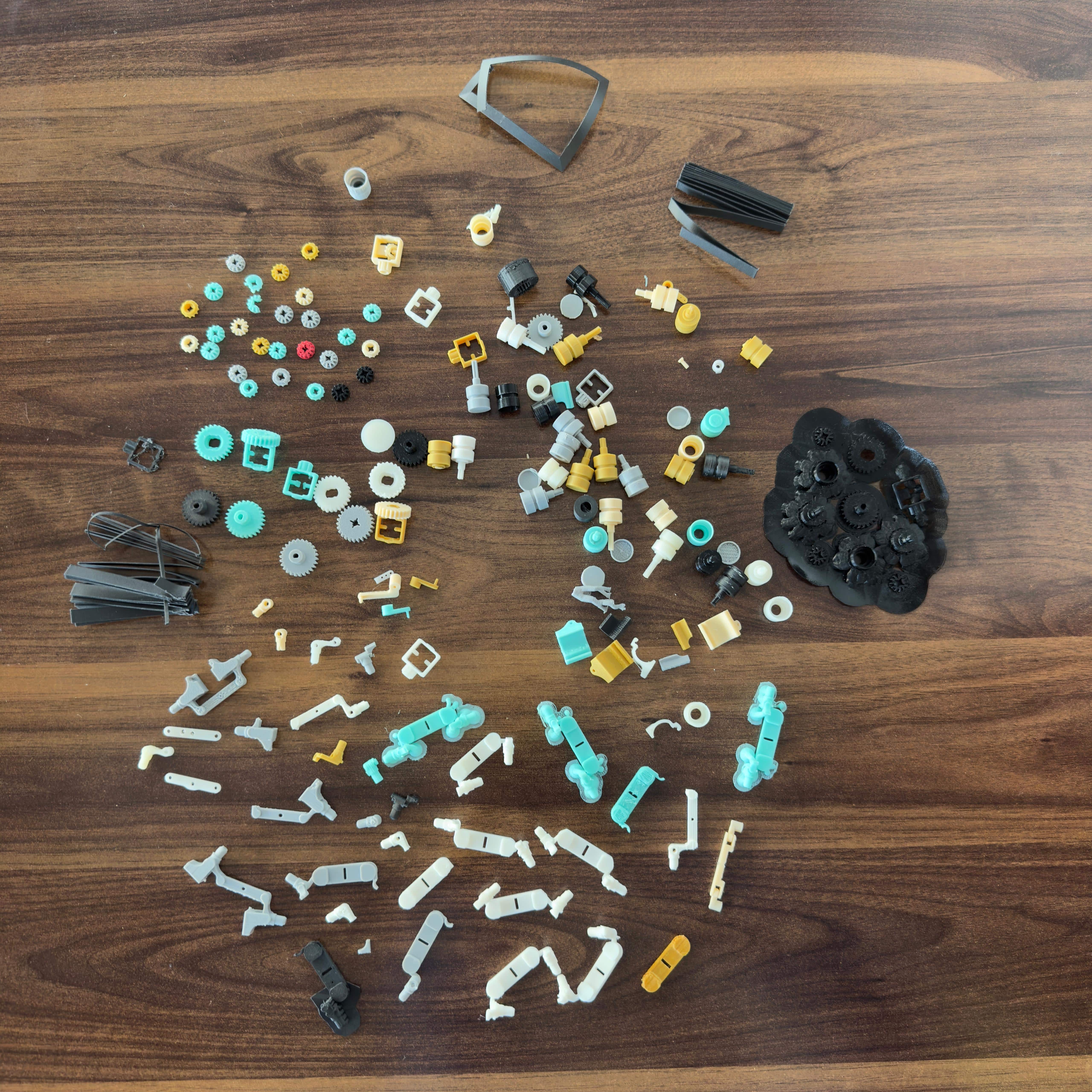
Comprehensive component evolution demonstrating our iterative design process across gear systems, steering mechanisms, and structural elements
**Development Scope & Engineering Iterations:** - **Gear System Evolution**: Multiple generations optimizing tooth profile, meshing efficiency, and strength - **Steering Mechanism Refinement**: Various iterations achieving precision control with minimal mechanical play - **Structural Component Optimization**: Chassis, rims, and mounting systems refined through performance testing - **Integration Validation**: Continuous testing ensuring component compatibility and system reliability - **Print-in-Place Validation**: Manufacturing process refinement for optimal production quality ## 🎯 Advanced Wheel & Tire System Engineering ### 🔍 Comprehensive Tire Analysis & Performance-Based Selection
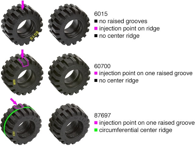
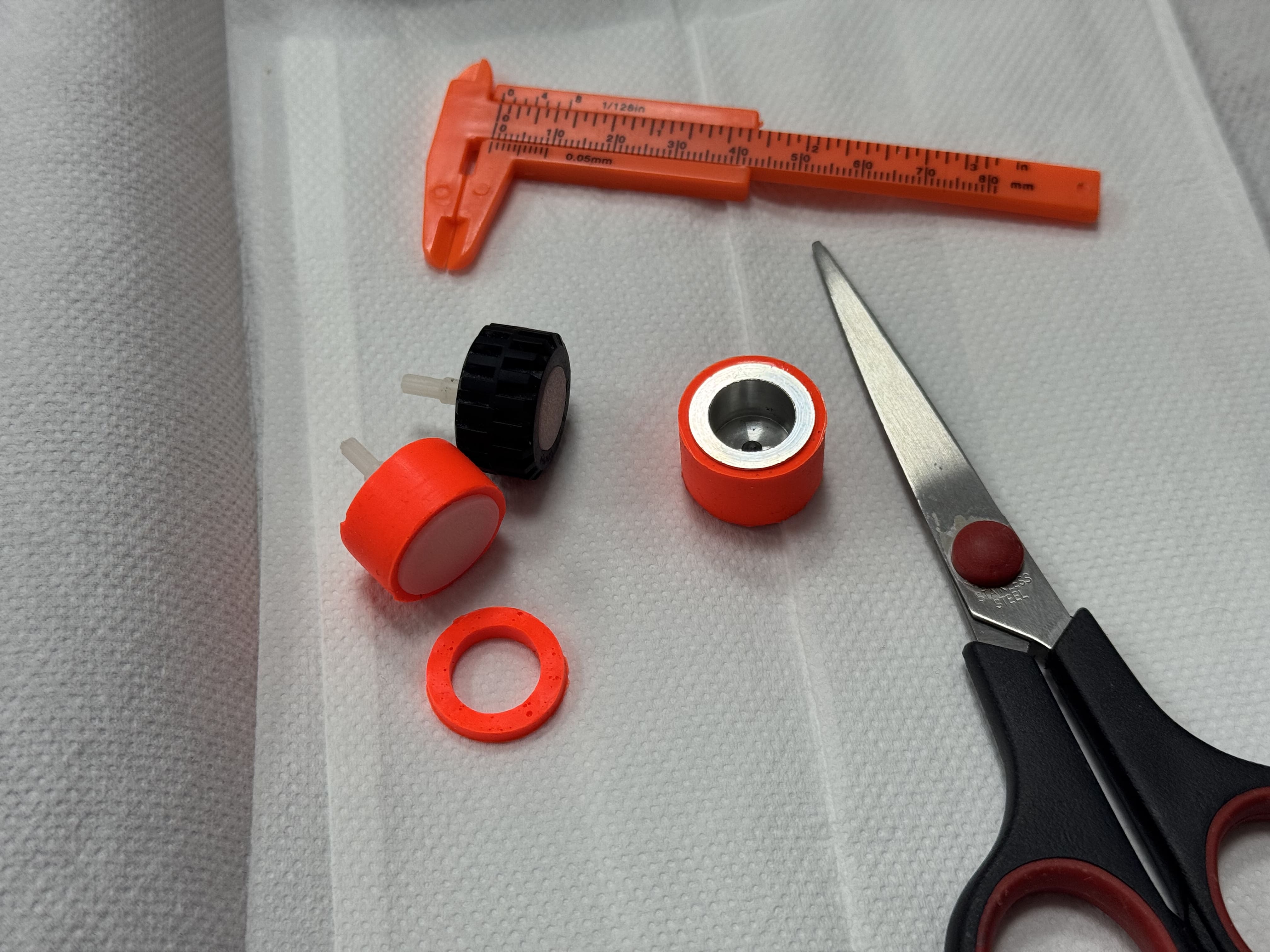
1) Detailed LEGO wheel variant analysis showing design differences • 2) Silicone vs LEGO tire performance comparison testing
**Technical Tire Comparison & Engineering Analysis:** | Engineering Aspect | LEGO 87697 | Custom Silicone Tires | |-------------------|------------|----------------------| | **Material Composition** | SEBS (Styrene-Ethylene-Butylene-Styrene) | Custom silicone compound formulation | | **Theoretical Traction** | Good predictable performance | Higher theoretical coefficient | | **Actual Performance** | Optimal for our weight class | Similar results despite theoretical advantage | | **Design Compatibility** | Perfect fit with custom rims | Required significant rim redesign | | **Manufacturing Consistency** | Excellent quality control | Variable performance between batches | | **Weight Impact** | Minimal additional mass | Slightly increased rotational mass due to a larger inner rim with more filling, necessary for better stretching of the silicone tire | **Final Engineering Selection: LEGO 87697** - **Optimal Dimensions**: 21mm diameter × 12mm width fitting our size constraints - **Key Design Feature**: Circumferential center ridge providing stability and predictable handling - **Performance Characteristics**: Consistent traction with minimal rolling resistance - **Reliability Assurance**: Proven durability under extended competition conditions ### 🎯 Performance Analysis: Why Theory Didn't Match Reality| 🏋️ Weight Dynamics 130g total weight changes traction physics |
⚡ Speed Factors 1.4 m/s momentum dominates cornering |
| 🎯 Precision Engineering Near-zero mechanical play in systems |
📊 Test Results Identical lap times with both tires |
| Primary structure with integrated mounting system |
| **4-Gear Differential** | [`design_4_gear_mini_differential.3mf`](design_4_gear_mini_differential.3mf) | 1 | | Complete differential assembly with 4-gear mechanism and gear slots|
| **Front Rim** | [`design_front_rim_bearing.3mf`](design_front_rim_bearing.3mf) | 2 | 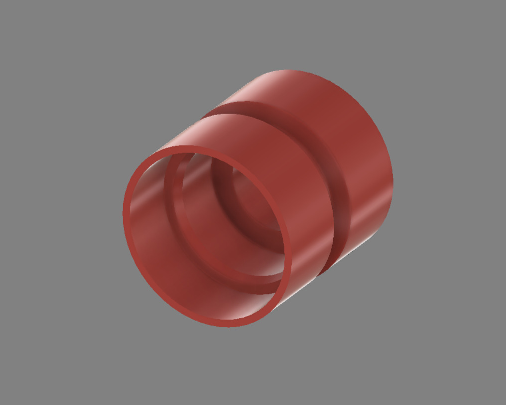
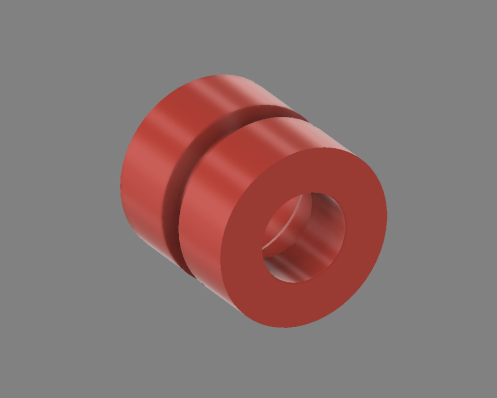 | Front wheel rims with integrated bearing seats (left/right) |
| **Steering Arm** | [`design_steering_arm.3mf`](design_steering_arm.3mf) | 2 |
| Front wheel rims with integrated bearing seats (left/right) |
| **Steering Arm** | [`design_steering_arm.3mf`](design_steering_arm.3mf) | 2 | 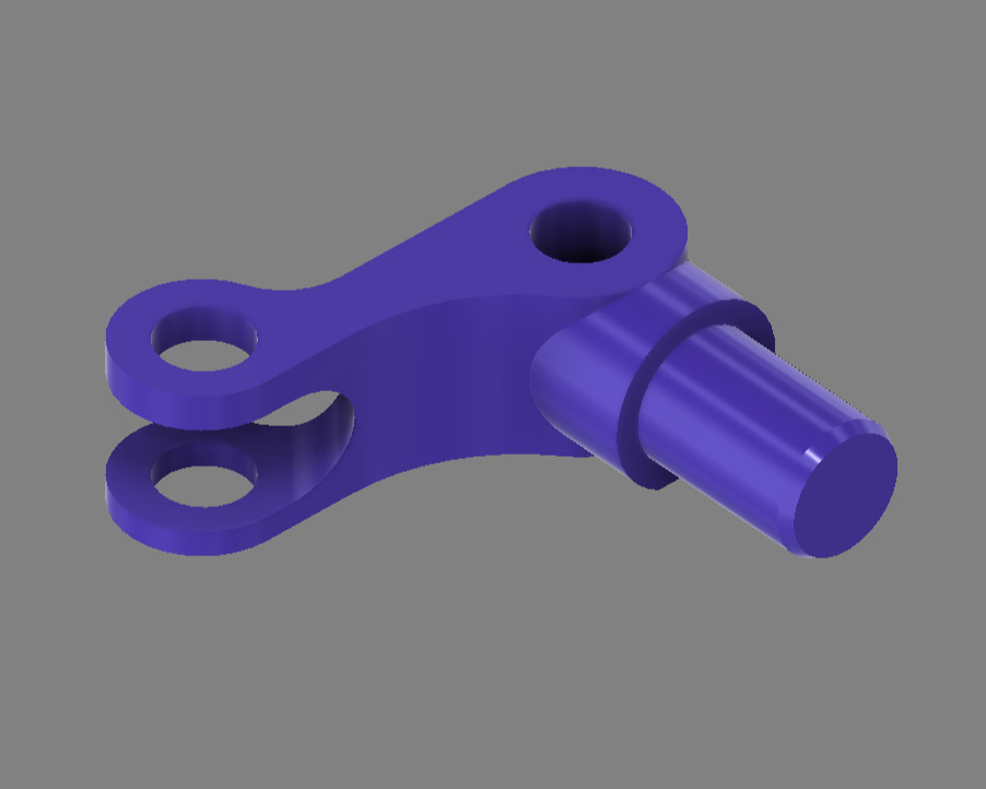
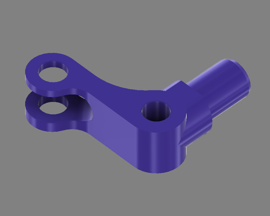 | Ackermann steering arms (left/right) |
| **Steering Linkage** | [`design_steering_linkage.3mf`](design_steering_linkage.3mf) | 1 |
| Ackermann steering arms (left/right) |
| **Steering Linkage** | [`design_steering_linkage.3mf`](design_steering_linkage.3mf) | 1 | 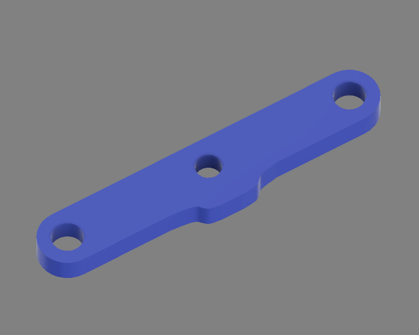 | Steering connection mechanism |
| **25T Spur Gear** | [`design_spur_25_gear.3mf`](design_spur_25_gear.3mf) | 1 |
| Steering connection mechanism |
| **25T Spur Gear** | [`design_spur_25_gear.3mf`](design_spur_25_gear.3mf) | 1 | 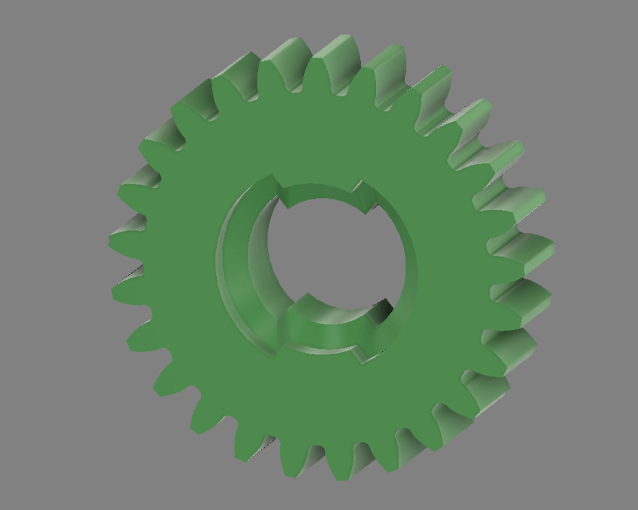
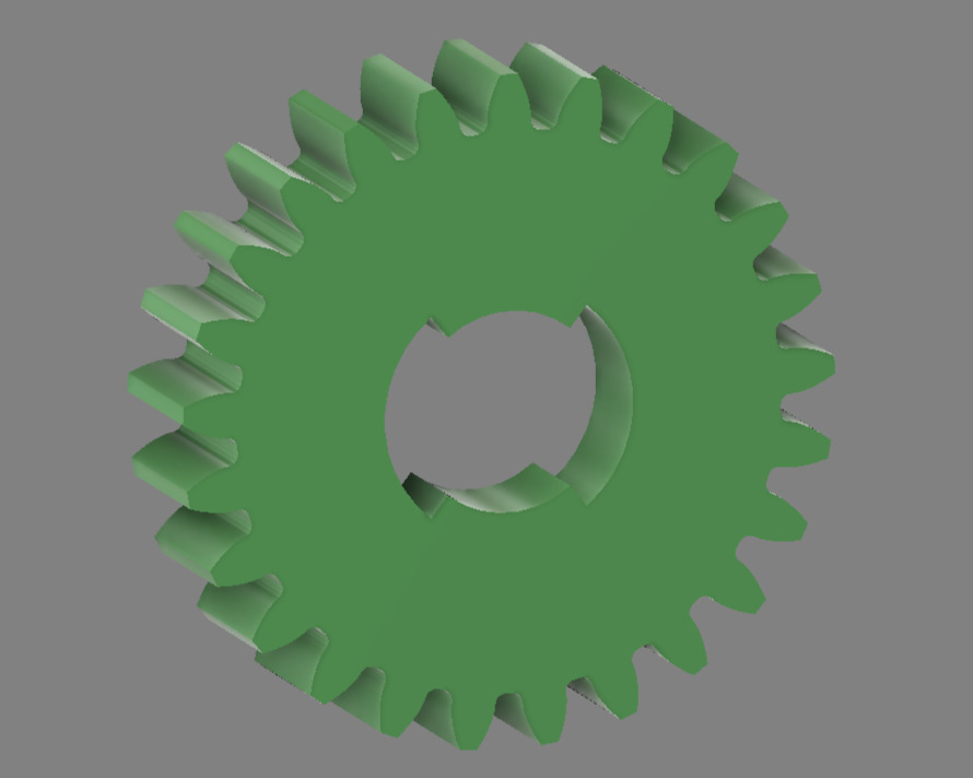 | 25-tooth torque transmission gear |
| **26T Spur Gear** | [`design_spur_26_gear.3mf`](design_spur_26_gear.3mf) | 1 |
| 25-tooth torque transmission gear |
| **26T Spur Gear** | [`design_spur_26_gear.3mf`](design_spur_26_gear.3mf) | 1 | 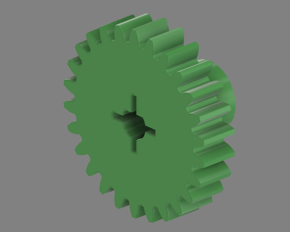
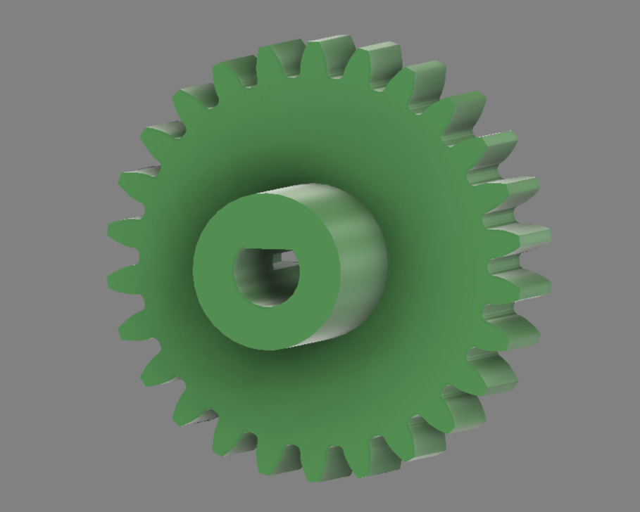 | 26-tooth motor output gear |
| **12T Bevel Gear** | [`design_bevel_12_gear.3mf`](design_bevel_12_gear.3mf) | 4 |
| 26-tooth motor output gear |
| **12T Bevel Gear** | [`design_bevel_12_gear.3mf`](design_bevel_12_gear.3mf) | 4 | 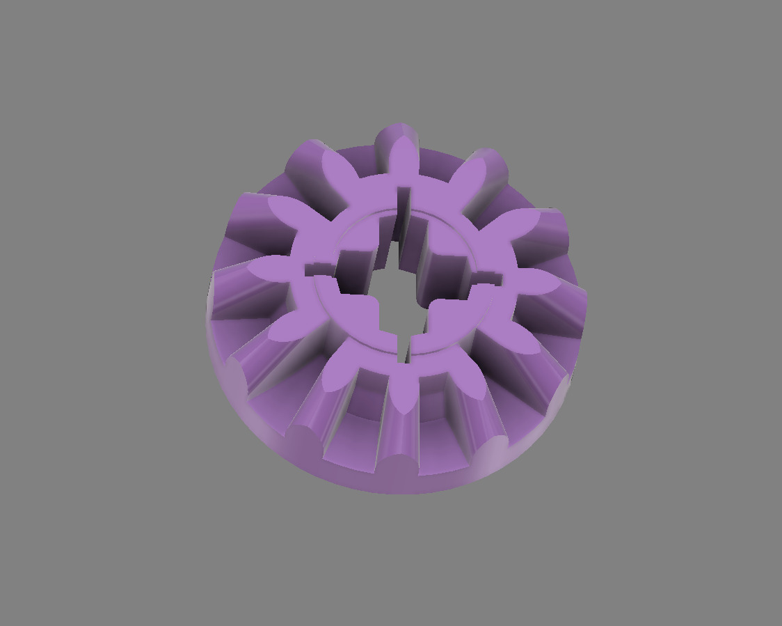
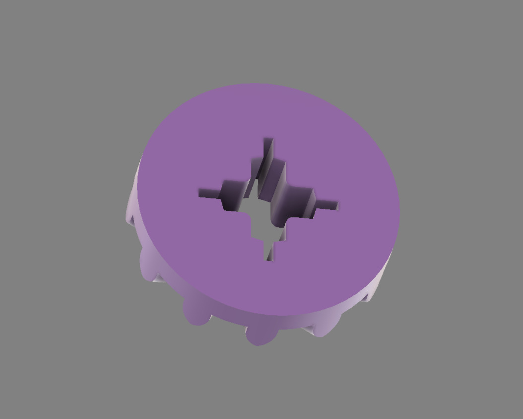 | Differential bevel gears (4 required for full assembly) |
| **Motor Lid** | [`design_motor_lid.3mf`](design_motor_lid.3mf) | 1 |
| Differential bevel gears (4 required for full assembly) |
| **Motor Lid** | [`design_motor_lid.3mf`](design_motor_lid.3mf) | 1 | 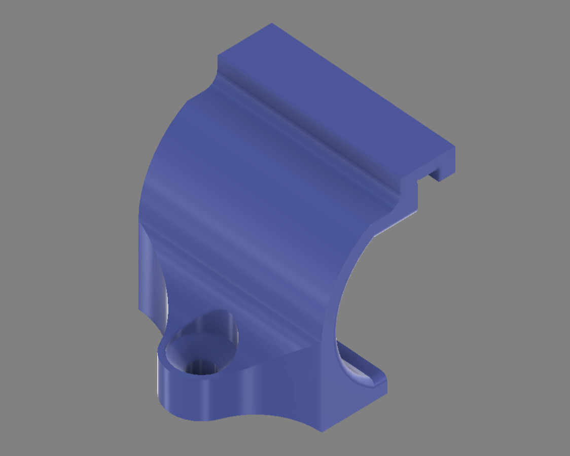 | N20 motor mounting enclosure |
| **Long Rear Rim** | [`design_back_rim_long.3mf`](design_back_rim_long.3mf) | 1 |
| N20 motor mounting enclosure |
| **Long Rear Rim** | [`design_back_rim_long.3mf`](design_back_rim_long.3mf) | 1 | 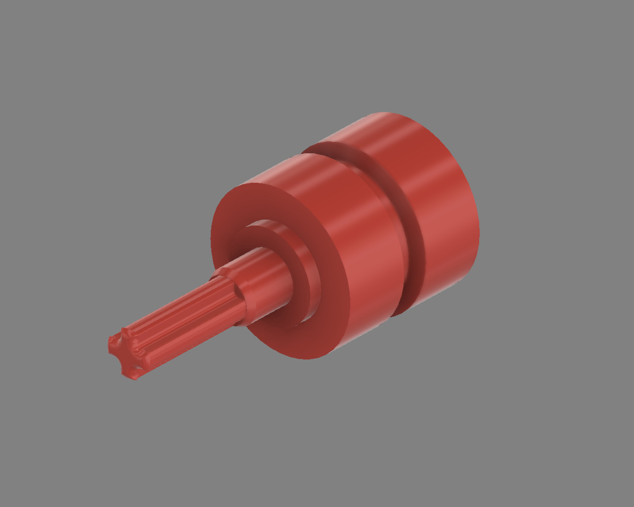 | Extended for right side, connecting farther from the gear |
| **Short Rear Rim** | [`design_back_rim_short.3mf`](design_back_rim_short.3mf) | 1 |
| Extended for right side, connecting farther from the gear |
| **Short Rear Rim** | [`design_back_rim_short.3mf`](design_back_rim_short.3mf) | 1 | 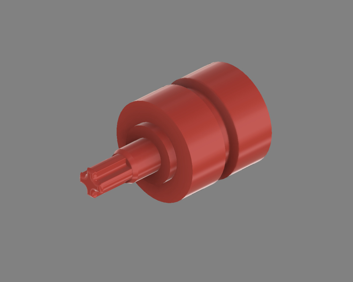 | Shorter for left side, connecting closer to the gear |
| **Front Top Cover** | [`design_front_top_cover.3mf`](design_front_top_cover.3mf) | 1 |
| Shorter for left side, connecting closer to the gear |
| **Front Top Cover** | [`design_front_top_cover.3mf`](design_front_top_cover.3mf) | 1 | 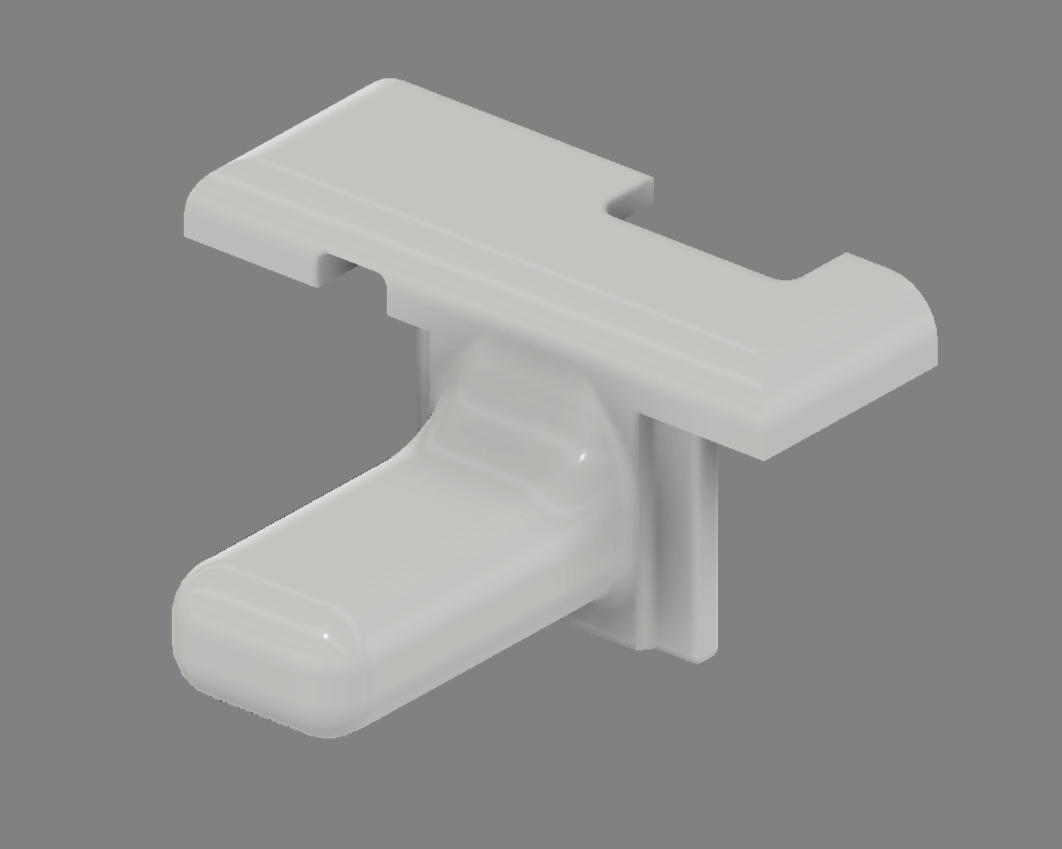
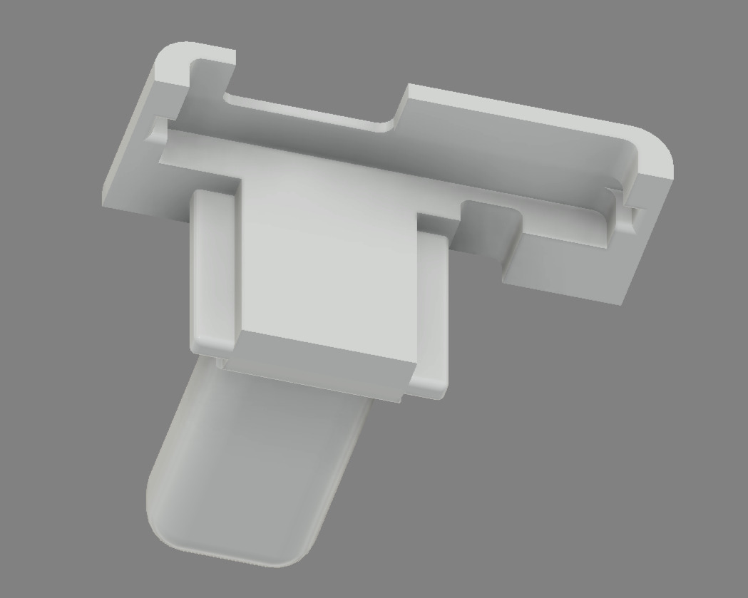 | Electronics protection cover |
| **Front Bottom Cover** | [`design_front_bottom_cover.3mf`](design_front_bottom_cover.3mf) | 1 |
| Electronics protection cover |
| **Front Bottom Cover** | [`design_front_bottom_cover.3mf`](design_front_bottom_cover.3mf) | 1 | 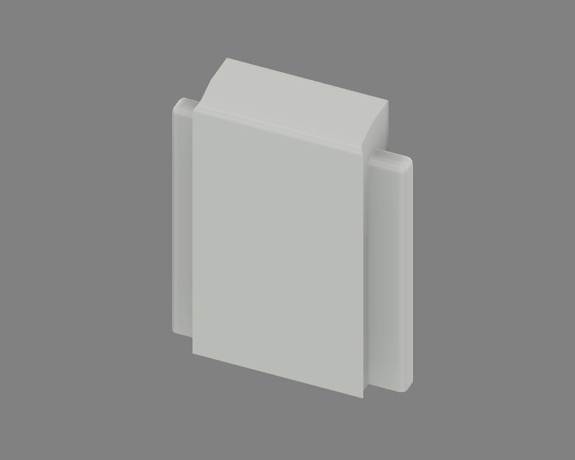 | Underbody protection |
| **Button Cap** | [`design_button_cap.3mf`](design_button_cap.3mf) | 1 |
| Underbody protection |
| **Button Cap** | [`design_button_cap.3mf`](design_button_cap.3mf) | 1 | 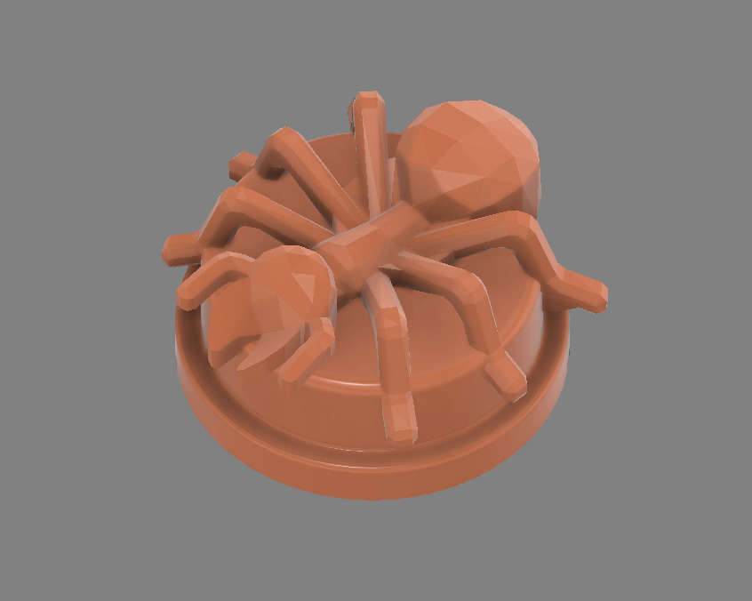
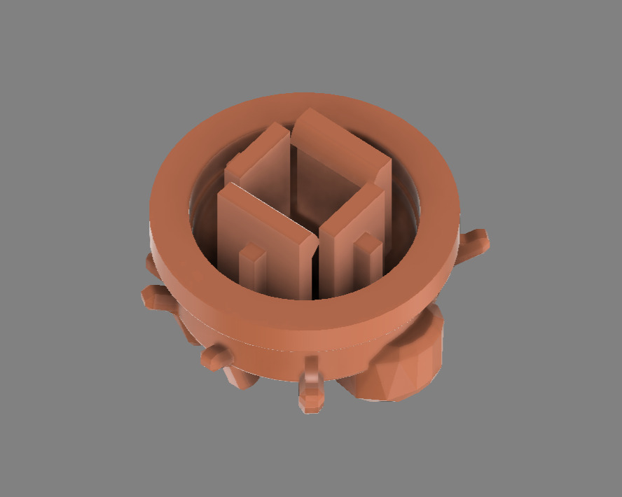 | Start button interface |
## 🚀 Engineering Design & Development Process
### 🔄 Comprehensive Iterative Engineering Approach
1. **Conceptual Design & Requirements Analysis**
- Comprehensive size constraint analysis and optimization
- True Ackermann steering geometry implementation and validation
- Strategic component integration planning and spatial optimization
2. **Precision CAD Modeling & Engineering Simulation**
- Detailed modeling in ***Autodesk Fusion*** with manufacturing considerations
- Motion simulation and validation for steering and drive train systems
3. **Prototyping & Performance Optimization**
- Multiple iterations for mechanical tolerance refinement and optimization
- Comprehensive material testing across various options and conditions
- Print-in-place component validation and manufacturing process refinement
4. **Production Engineering & System Validation**
- Optimized printing parameters implementation for production quality
- Comprehensive assembly procedure development and documentation
- Competition condition performance testing and validation
## ✅ Engineering Validation & Testing Protocols
### 🧪 Mechanical System Verification & Performance Testing
- **Differential Operation Validation**: Comprehensive testing of smooth torque distribution under various load conditions
- **Steering Geometry Confirmation**: Physical validation of true Ackermann principles in operational implementation
- **Structural Integrity Assessment**: Testing under various surface irregularities to confirm reliability, focusing on the effects of small bumps on a lightweight vehicle.
- **Bearing System Performance**: Long-term testing confirming smooth operation, minimal friction, and reliability
### 🏆 Competition Readiness & Reliability Engineering
- **Regulation Compliance Verification**: Comprehensive adherence to WRO vehicle specifications including 300x200mm maximum dimensions, 1.5kg maximum weight, 4-wheel design with one driving axle and one steering actuator
- **Operational Reliability Demonstration**: Extended testing showing consistent performance under competition pressure
- **Maintenance & Service Protocols**: Established procedures for competition-time adjustments and repairs
- **Backup System Preparation**: Redundant components and systems prepared for competition requirements
---
This comprehensive mechanical documentation provides complete transparency into our design process, manufacturing methods, validation procedures, and engineering decision-making. Every aspect of our mechanical system has been optimized for the unique challenges of autonomous navigation in the WRO 2025 Future Engineers category, enabling exact duplication while demonstrating engineering excellence through detailed component specifications, assembly instructions, performance data, and real-world validation.
For electrical systems documentation: [Schemes Documentation](../schemes/README.md)
For software implementation and algorithms: [Software Documentation](../src/README.md)
For performance demonstrations: [Video Documentation](../video/README.md)
For additional resources and photos: [Other Documentation](../other/README.md)
| Start button interface |
## 🚀 Engineering Design & Development Process
### 🔄 Comprehensive Iterative Engineering Approach
1. **Conceptual Design & Requirements Analysis**
- Comprehensive size constraint analysis and optimization
- True Ackermann steering geometry implementation and validation
- Strategic component integration planning and spatial optimization
2. **Precision CAD Modeling & Engineering Simulation**
- Detailed modeling in ***Autodesk Fusion*** with manufacturing considerations
- Motion simulation and validation for steering and drive train systems
3. **Prototyping & Performance Optimization**
- Multiple iterations for mechanical tolerance refinement and optimization
- Comprehensive material testing across various options and conditions
- Print-in-place component validation and manufacturing process refinement
4. **Production Engineering & System Validation**
- Optimized printing parameters implementation for production quality
- Comprehensive assembly procedure development and documentation
- Competition condition performance testing and validation
## ✅ Engineering Validation & Testing Protocols
### 🧪 Mechanical System Verification & Performance Testing
- **Differential Operation Validation**: Comprehensive testing of smooth torque distribution under various load conditions
- **Steering Geometry Confirmation**: Physical validation of true Ackermann principles in operational implementation
- **Structural Integrity Assessment**: Testing under various surface irregularities to confirm reliability, focusing on the effects of small bumps on a lightweight vehicle.
- **Bearing System Performance**: Long-term testing confirming smooth operation, minimal friction, and reliability
### 🏆 Competition Readiness & Reliability Engineering
- **Regulation Compliance Verification**: Comprehensive adherence to WRO vehicle specifications including 300x200mm maximum dimensions, 1.5kg maximum weight, 4-wheel design with one driving axle and one steering actuator
- **Operational Reliability Demonstration**: Extended testing showing consistent performance under competition pressure
- **Maintenance & Service Protocols**: Established procedures for competition-time adjustments and repairs
- **Backup System Preparation**: Redundant components and systems prepared for competition requirements
---
This comprehensive mechanical documentation provides complete transparency into our design process, manufacturing methods, validation procedures, and engineering decision-making. Every aspect of our mechanical system has been optimized for the unique challenges of autonomous navigation in the WRO 2025 Future Engineers category, enabling exact duplication while demonstrating engineering excellence through detailed component specifications, assembly instructions, performance data, and real-world validation.
For electrical systems documentation: [Schemes Documentation](../schemes/README.md)
For software implementation and algorithms: [Software Documentation](../src/README.md)
For performance demonstrations: [Video Documentation](../video/README.md)
For additional resources and photos: [Other Documentation](../other/README.md)