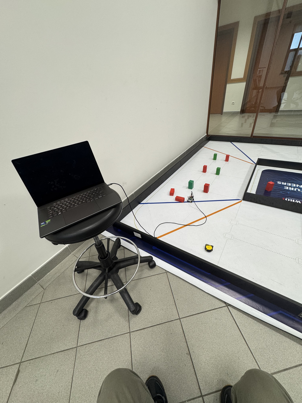
Software development and testing environment
| ## 🎯 Software Architecture Overview Our software system implements a distributed architecture with two microcontrollers communicating via UART protocol: - **STM32H747 (Camera MCU)**: Runs MicroPython for high-level navigation, computer vision, and main control logic - **nRF52832 (Sensor MCU)**: Runs Arduino C++ for real-time sensor data acquisition and preprocessing - **Bidirectional UART Communication**: 115200 baud rate for seamless data exchange between processors |
Software development and testing environment |
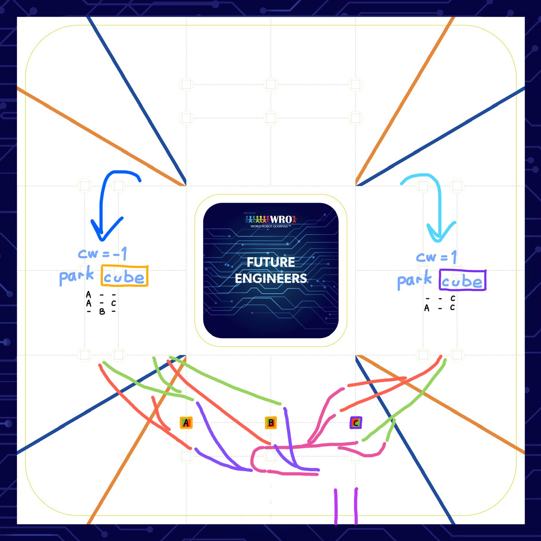
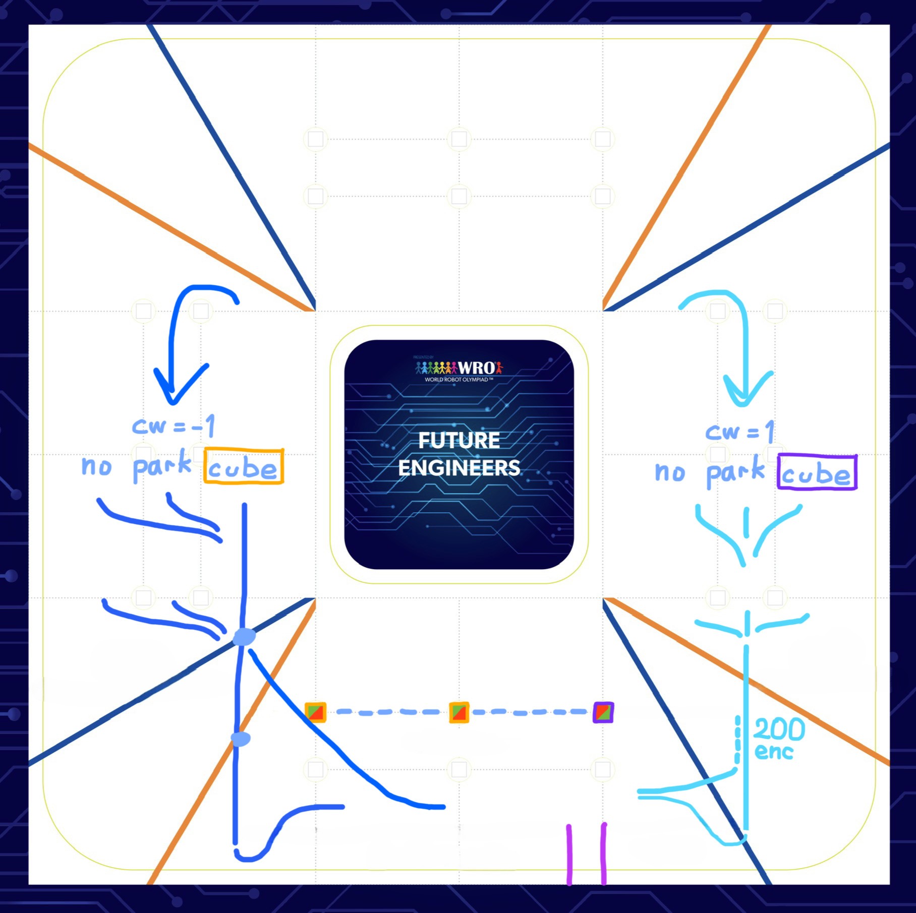
1) Parking paths including correct final cube avoidance • 2) Direct parking entry without checking final cube
### Obstacle Combination Strategies Our algorithm handles all possible obstacle configurations for both directions:
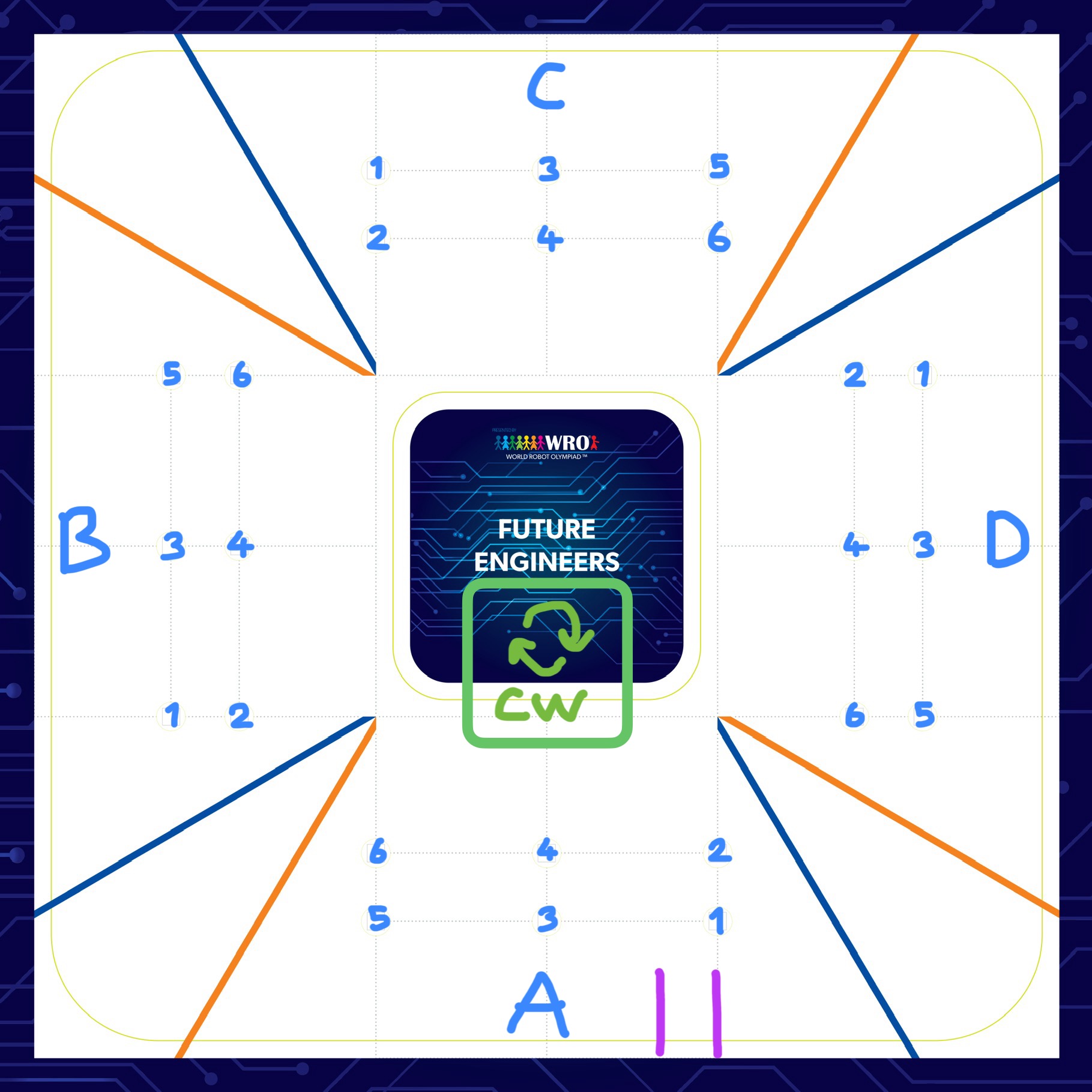
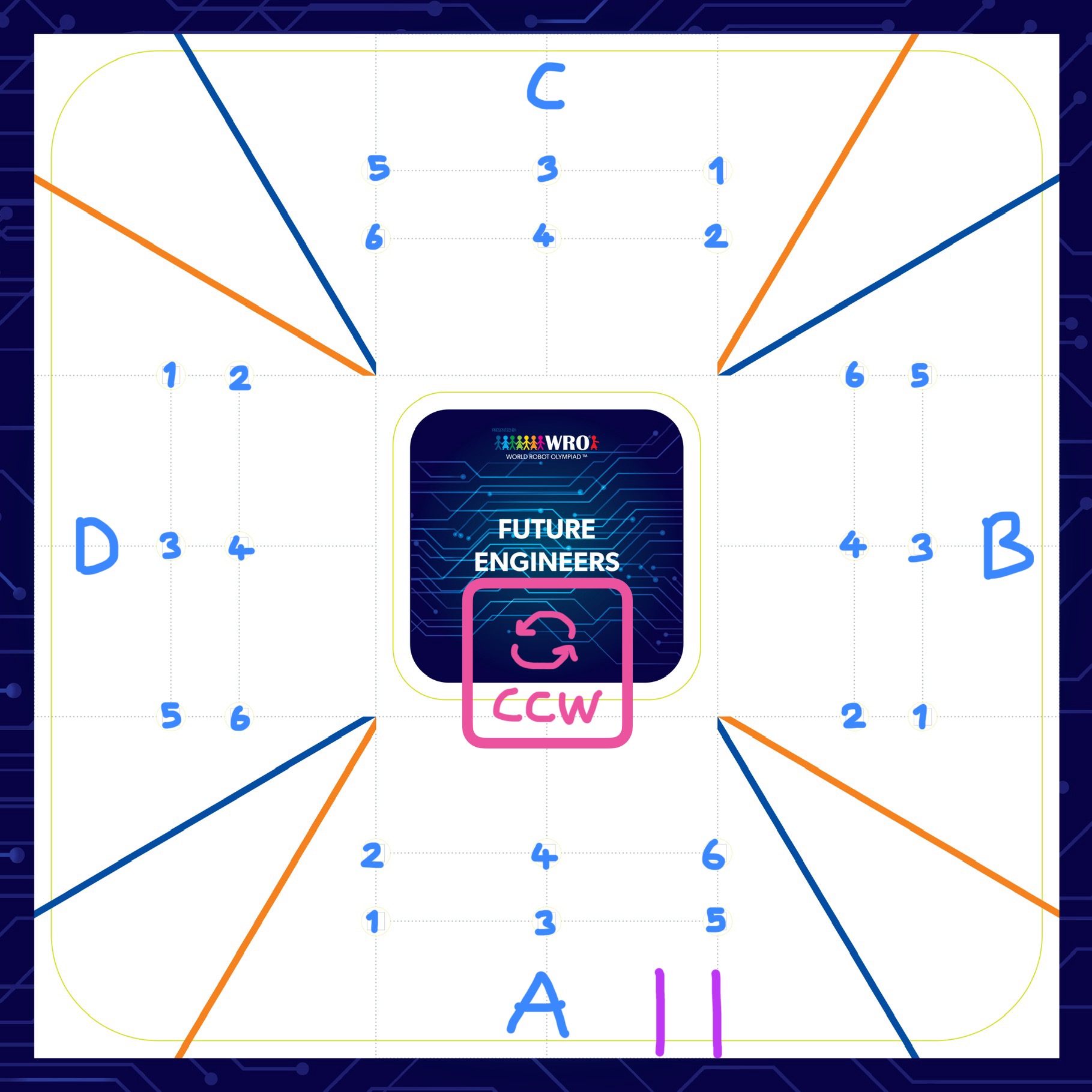
1) Clockwise navigation with A,B,C,D obstacle combinations 1-6 • 2) Counter-clockwise navigation with A,B,C,D obstacle combinations 1-6
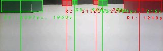
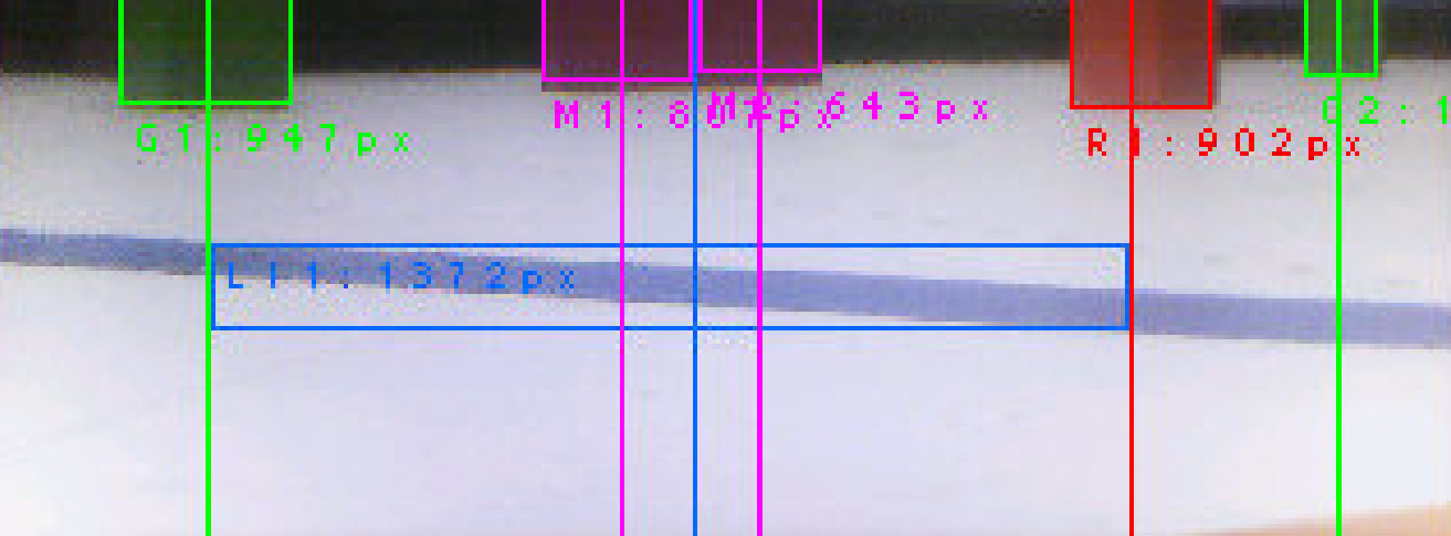
## 🎨 Computer Vision System ### CIELAB Color Space Selection We chose the **CIELAB color space** for superior color differentiation under varying lighting conditions compared to traditional RGB or HSV spaces. Our custom `ANTi_threshold_finder.m` MATLAB code helped us determine optimal thresholds for reliable detection through systematic analysis of color distributions under various lighting conditions. **Color Thresholds (L_min, L_max, A_min, A_max, B_min, B_max)**: ```python th = { "R": [(25, 65, 35, 75, -10, 20)], # Red obstacle "G": [(30, 70, -40, -10, 10, 50)], # Green obstacle "M": [(40, 80, 60, 90, -20, 30)], # Magenta parking "BK": [(0, 25, -10, 20, -15, 10)], # Black wall "O": [(5, 60, 5, 20, 0, 25)], # Orange corner "B": [(5, 60, 5, 80, -80, -25)] # Blue corner } ``` ### Vision Processing Pipeline 1. **Image Acquisition**: 320x240 QVGA resolution at 26 FPS 2. **Color Conversion**: RGB565 to CIELAB color space 3. **Blob Detection**: `find_blobs()` with area and pixel thresholds 4. **Target Selection**: Largest blob for reliability 5. **Error Calculation**: Centroid deviation from camera center
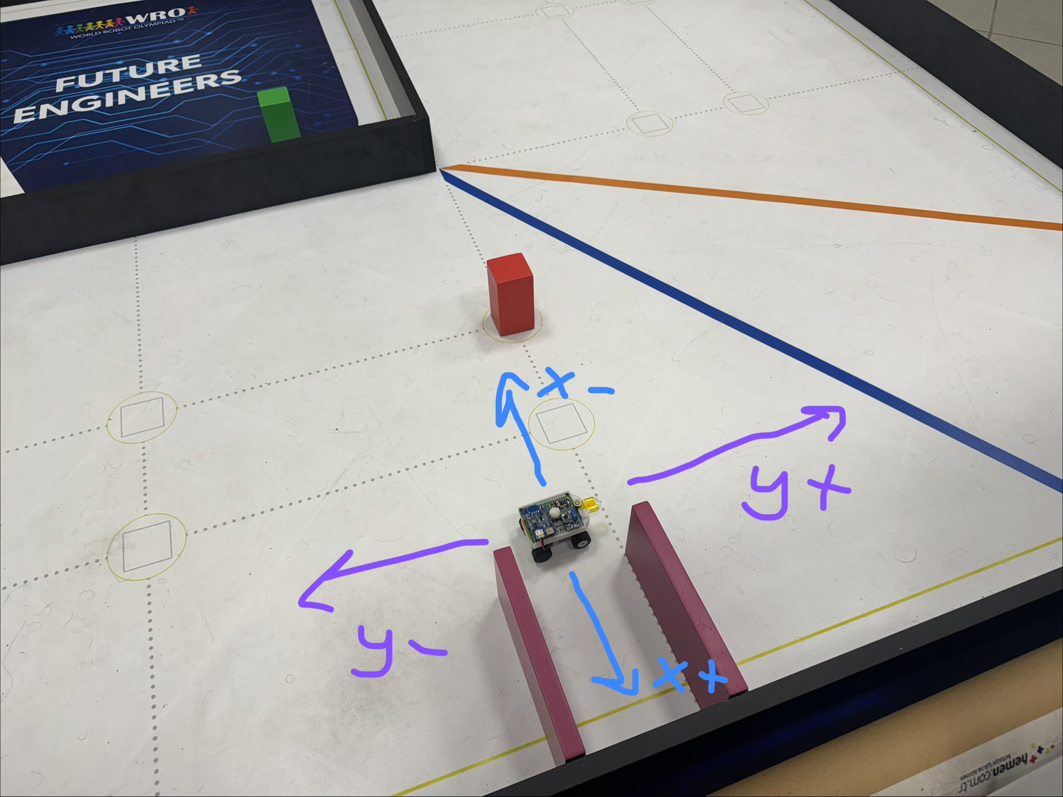
Coordinate system for encoder-based position tracking (Y+ forward, Y- backward, X- left, X+ right)
**Sensor Fusion Strategy**: - **Primary**: Camera vision for precise positioning - **Secondary**: IMU gyroscope for heading maintenance - **Tertiary**: ToF sensors for parking detection - **Extra fallback**: Encoder odometry solution tested and ready to implement as backup for distance tracking ### UART Communication Protocol **Bidirectional Communication Architecture**: The UART communication between STM32H747 (master) and nRF52832 (slave) implements a robust bidirectional protocol at 115200 baud rate: **Master (STM32H747) → Slave (nRF52832) Commands**: - `'r'` - Request all sensor data (left_tof, right_tof, encoder) - `'t'` - Request left ToF sensor only - `'u'` - Request right ToF sensor only - `'e'` - Request encoder travel distance only - `'z'` - Reset encoder counter to zero **Slave Response Formats**: - **All sensors**: `left_distance,right_distance,encoder_distance\n` - **Left ToF only**: `left_distance\n` - **Right ToF only**: `right_distance\n` - **Encoder only**: `encoder_distance\n` **Communication Initialization**: 1. **Slave Ready Signal**: nRF52832 sends `0x01` byte when initialized 2. **Master Detection**: STM32H747 waits for ready signal with timeout 3. **Command Cycle**: Continuous request-response pattern during operation **Data Packet Structure**: - **Command Byte**: Single character sent from master - **Response Data**: Comma-separated values or single value from slave - **Termination**: Newline character (`\n`) marks end of transmission - **Timeout Handling**: 50ms timeout prevents communication deadlocks **Multi-Sensor Data Transmission**: The slave efficiently packages sensor readings into optimized responses: - **ToF Sensors**: Left and right distance values (0-4000mm range) with bounds checking - **Encoder Data**: Travel distance in millimeters with float precision (2 decimal places) - **Data Integrity**: Validation and error handling on both ends **Hardware Configuration**: ```python # STM32H747 UART setup uart = UART(9, baudrate=115200, bits=8, parity=None, stop=1) ``` **Code Example from obstacle.py**: ```python def fetch_data(command, timeout=50): # Send command to slave and parse response global tof_left, tof_right, encoder, uart_buffer uart.write(command) if command in (b'z', b'p'): return True # No response needed start_time = pyb.millis() while pyb.elapsed_millis(start_time) < timeout: if uart.any(): uart_buffer += uart.read(uart.any()) if b'\n' in uart_buffer: line, uart_buffer = uart_buffer.split(b'\n', 1) if command == b'r' and line.count(b',') == 2: parts = line.split(b',') tof_left = int(parts[0]) tof_right = int(parts[1]) encoder = float(parts[2]) return True return False # Timeout ``` **Code Example from uart_slave.ino**: ```cpp void processUARTCommand(char command) { // Process commands from main vehicle controller int left_dist = readDistanceSensor(LEFT_DISTANCE_SENSOR_ADDR); int right_dist = readDistanceSensor(RIGHT_DISTANCE_SENSOR_ADDR); float travel_distance = encoder_count / PULSES_PER_MILLIMETER; switch (command) { case 'r': // Return all sensor readings: left_tof,right_tof,encoder SERIAL_PORT.print(left_dist); SERIAL_PORT.print(','); SERIAL_PORT.print(right_dist); SERIAL_PORT.print(','); SERIAL_PORT.println(travel_distance, 2); break; case 't': // Left sensor only SERIAL_PORT.println(left_dist); break; case 'u': // Right sensor only SERIAL_PORT.println(right_dist); break; case 'e': // Encoder travel distance SERIAL_PORT.println(travel_distance, 2); break; case 'z': // Reset encoder counter encoder_count = 0; break; default: // Unknown command - ignore break; } } ``` **Communication Flow**: 1. **Master Request**: STM32H747 sends single character command 2. **Slave Processing**: nRF52832 reads sensors and formats response 3. **Data Transmission**: Slave sends formatted data with newline termination 4. **Master Parsing**: STM32H747 receives and parses data into global variables 5. **Buffer Management**: Circular buffer handles partial messages and timeouts This protocol provides flexible sensor data access while maintaining efficient communication bandwidth usage. ## 🛠️ Engineering Challenges & Solutions ### Real-Time Performance Optimization **Challenge**: MicroPython interpretation overhead affecting control loop frequency **Solution**: - Optimized blob detection with restricted ROIs - Pre-computed color thresholds - Efficient UART data parsing - Balanced control loop timing (15-30ms cycles) ### IMU Integration Strategy **Challenge**: Hardware interrupt-based IMU reading caused significant runtime performance decrease, affecting camera operation and framerate **Solution**: We implemented a basic IMU calculation approach executed each control loop cycle rather than using interrupts. Despite theoretical advantages of interrupt-based IMU, our solution proved sufficient because: - **Control Loop Speed**: Each cycle executes rapidly enough for accurate angle integration - **Camera Priority**: Maintaining high camera framerate was critical for reliable color detection - **Sufficient Accuracy**: Even with basic integration, our IMU provided perfect angle values for vehicle navigation - **Performance Validation**: Achieved competition-best times (16s Open, 35s Obstacle) confirming IMU reliability **10-Second IMU Calibration Routine:**: ```python # Collect 1000 samples to determine zero offset calibration_samples = 1000 calibration_sum = 0.0 while calibration_count < calibration_samples: gyro_sample = read_gyro() calibration_sum += gyro_sample calibration_count += 1 gyro_zero_offset = calibration_sum / calibration_count ``` **Implementation**: ```python # Basic gyro integration each control cycle gyro = read_gyro() - gyro_zero_offset angle += gyro * dt ``` This approach allowed us to maintain both high-performance camera operation and accurate IMU readings, demonstrating that sometimes simpler solutions can be more effective in integrated systems. ### 🅿️ Parallel Parking Strategy Optimization **🚧 Challenge**: Our compact vehicle design (69mm length) required extremely precise parallel parking maneuvers within the tight 1.5× vehicle length parking space (103.5mm) **💡 Initial Solution**: We designed and implemented a strategic front extension piece that provided crucial benefits: - **📏 Length Extension**: Added 21mm front piece increased total vehicle length to 90mm - **Parking Space Optimization**: Parking lot requirement became 90mm × 1.5 = 135mm (13.5cm) - **Critical Width Design**: The narrow width of the extension piece allowed clearance from parking walls during turning maneuvers - **🔄 Improved Maneuverability**: Additional space enabled more reliable parking execution **Multi-Stage Parking Maneuver**: 1. **Approach**: Follow magenta wall with camera guidance 2. **Turn-in**: 80-degree turn outside parking spot 3. **Alignment**: Odometry-based reverse positioning 4. **Reverse**: Controlled backing for final alignment 5. **Straighten**: Final orientation adjustment > 💡🐜 ***Fun Discovery***: The distinctive front extension piece gave our vehicle a unique appearance that reminded us of an **ANT**'s mandible, perfectly matching our team name and creating a memorable visual identity!
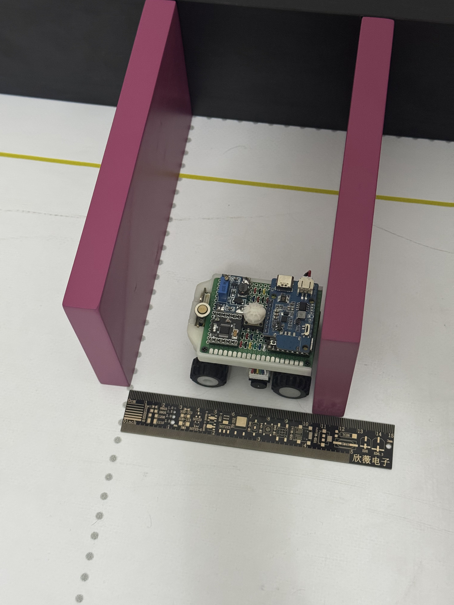
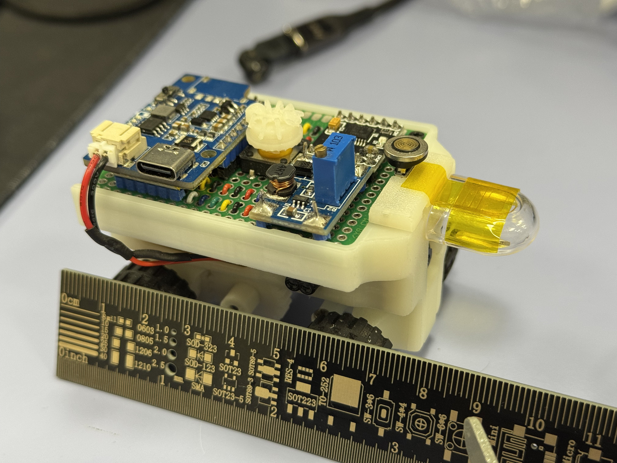
1) Original 69mm vehicle in tight parking space • 2) Extended 90mm vehicle with strategic front piece
**💡 Final Evolution**: After extensive testing, we iterated on the extension design to further enhance safety and performance: - **📏 Enhanced Length**: Increased extension to 41mm for total vehicle length of 110mm - **Parking Space Adjustment**: Expanded requirement to 110mm × 1.5 = 165mm - **Improved Safety Margin**: Greater clearance for multi-turn maneuvers while maintaining higher speeds - **Design Refinements**: Incorporated competition stickers creating "ANTi" branding and ant-inspired eyes - **Maneuver Strategy**: Retained multiple-turn parking for optimal speed-safety balance
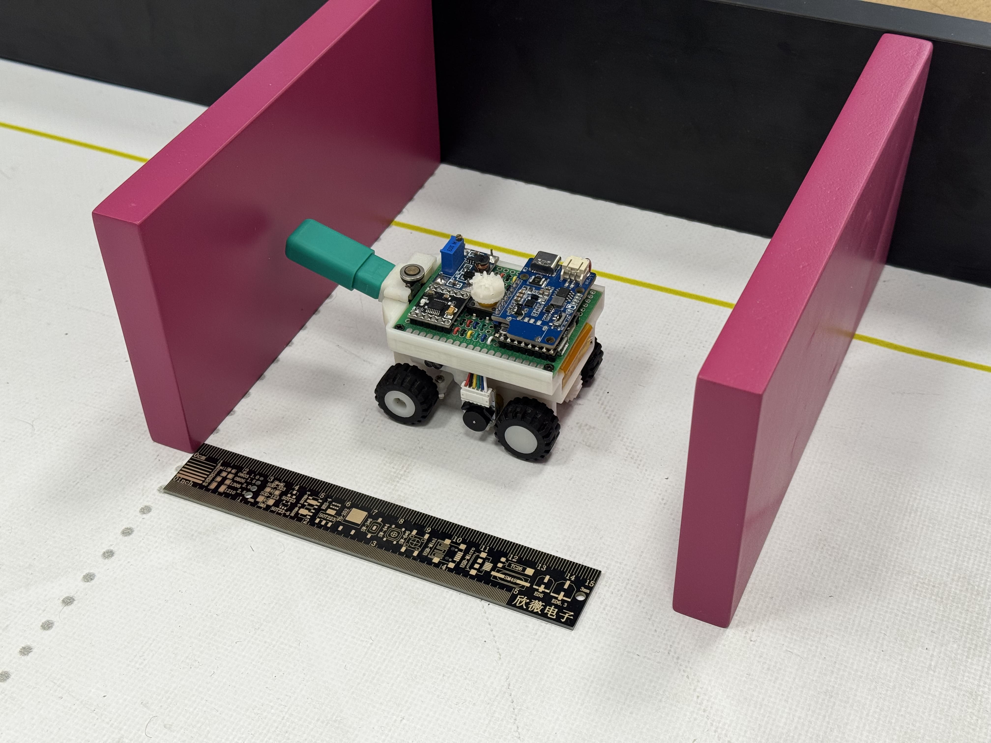
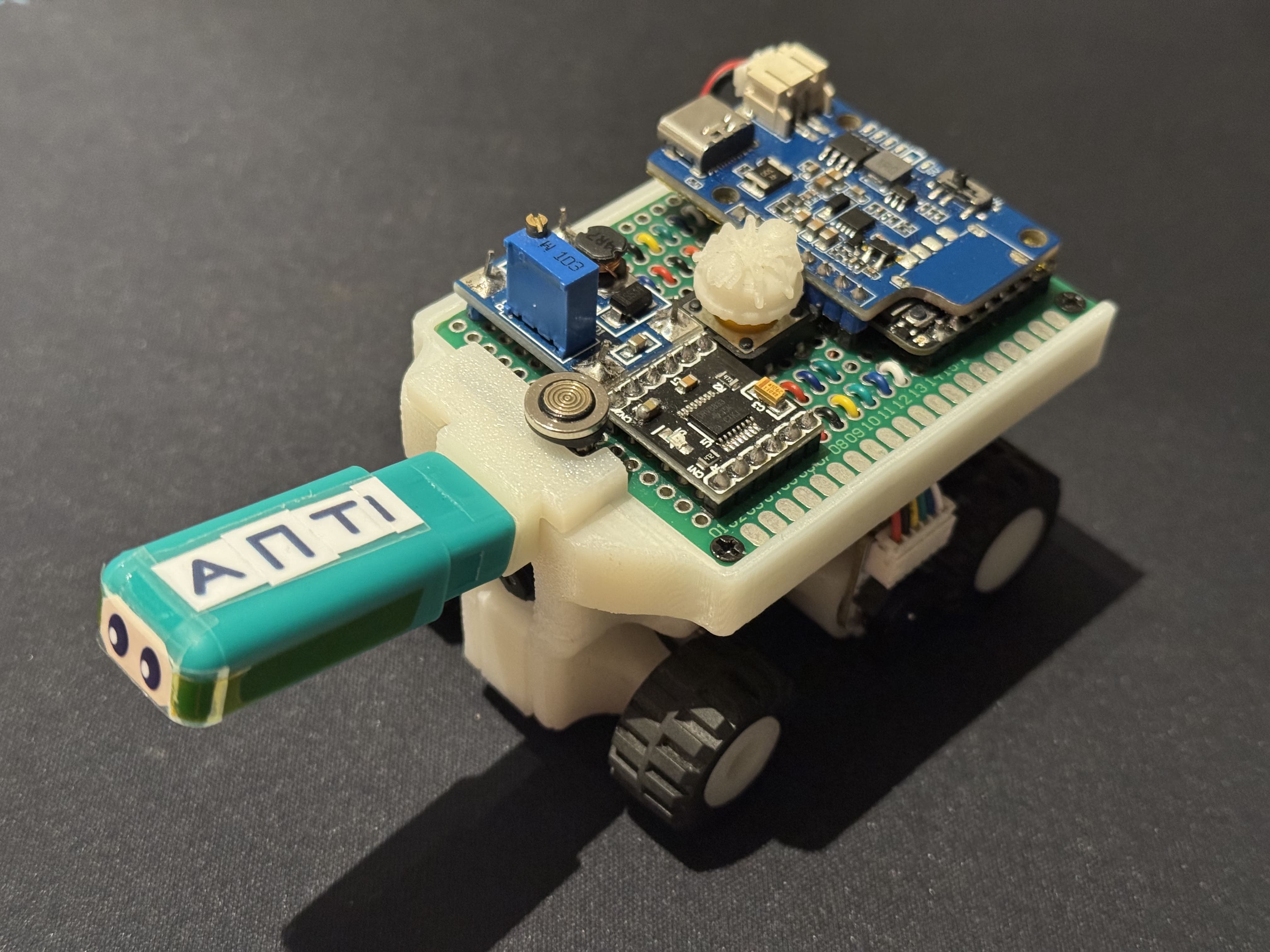
1) Final 110mm vehicle in 165mm parking space with measurement verification • 2) Close-up of refined extension with custom branding and visual enhancements
### Lighting Condition Adaptation **🌅 Challenge**: Varying competition lighting conditions affecting color detection accuracy **💡 Solution**: - 🎨 **CIELAB Color Space** for superior lighting invariance compared to traditional RGB or HSV spaces - 📊 **MATLAB Analysis** using our custom `ANTi_threshold_finder.m` code for systematic color distribution analysis - **Extensive Calibration** under multiple lighting conditions including direct sunlight - ⚙️ **Dynamic Threshold Adjustment** based on ambient light levels - **Robust Blob Detection Parameters** with optimized area and pixel thresholds
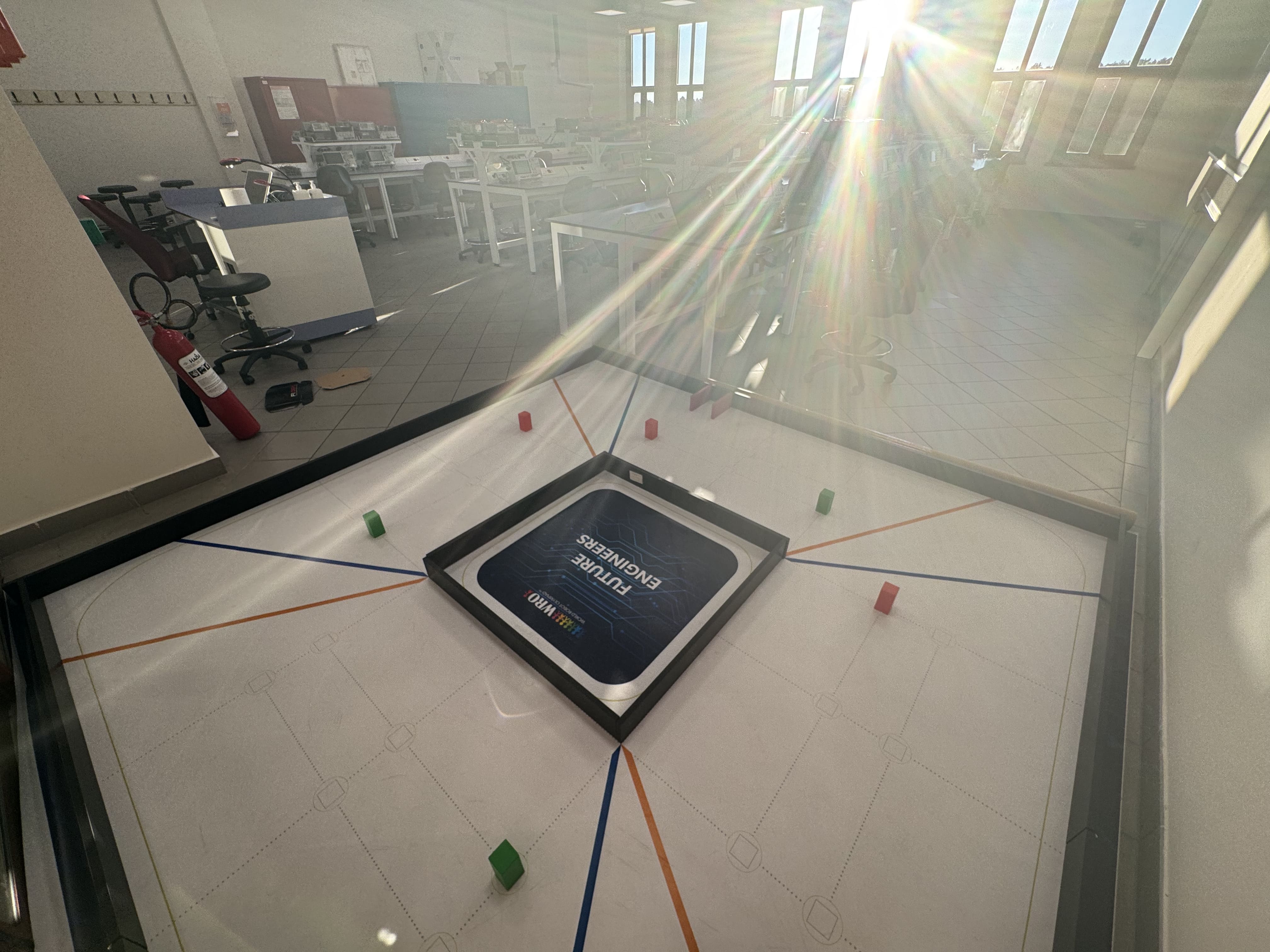
Comprehensive testing under challenging lighting conditions including direct sunlight
## 📊 Navigation Flow & State Machines ### ⚡ Open Challenge Detailed Strategy **Initial Phase - Direction Determination**: 1. **Unknown Start**: Begin with direction = 0 (unknown) 2. **Forward Approach**: Drive straight using IMU guidance only 3. **Color Detection**: Simultaneously detect orange or blue markers 4. **Direction Assignment**: First detected color sets direction (orange: CW=1, blue: CCW=-1) 5. **ToF Transition**: Switch to camera guidance when front ToF detects <800mm **Main Navigation Phase**: - **Wall Following**: Camera-based black wall tracking with PID control - **Corner Detection**: Orange/blue markers increment corner count - **Precise Turns**: 90-degree turns using IMU gyro integration - **Segment Management**: Encoder-based distance tracking between corners ### 🚦Obstacle Following Approach Our obstacle navigation implements an advanced following strategy that maintains optimal positioning: **Core Following Logic**: - **Consistent Positioning**: Maintain obstacles at specific X pixel positions in camera frame - **Offset Calculation**: Different offsets for inner (30px) and outer (30px) obstacles based on direction - **Smooth Tracking**: PID control combines camera error with heading error for smooth combined sensor fusion and vehicle motion - **Shortest Path**: Algorithm always forms the most direct path around obstacles **Color-Specific Behavior**: - **Red Obstacles**: Keep at *CAM_CENTER - offset* (left offset positioning for proper right avoidance) - **Green Obstacles**: Keep at *CAM_CENTER + offset* (right offset positioning for proper left avoidance) - **Adaptive Offsets**: Direction and color dependent offset calculation for universal strategy - **Sensor Fusion**: Heading IMU sensor combined with camera vision for smooth, stable control approach **Performance Advantage**: This approach enables both high speed (1.4 m/s operational) and minimal oscillation, creating the smoothest target-driven algorithm in the competition through precise sensor fusion of vision and angle guidance. ## 🧪 Testing & Validation ### Test Suite (`/tests` Directory) - [`blink.py`](tests/blink.py) - LED and basic I/O verification - [`camera_test.py`](tests/camera_test.py) - Camera functionality and color detection - [`imu_test.py`](tests/imu_test.py) - Gyroscope calibration and reading - [`tof_test.py`](tests/tof_test.py) - Distance sensor validation - [`button_photo.py`](tests/button_photo.py) - Input device testing ### Simulation Concept We initially developed a Webots simulation (`ANTi_wro_sim.wbt`) as a universal testing platform. However, due to timeline constraints and the complexity of accurately modeling our custom mechanical systems and sensor behaviors, we converted our development focus directly to physical implementation. The simulation served as a valuable conceptual framework before transitioning to real-world testing.
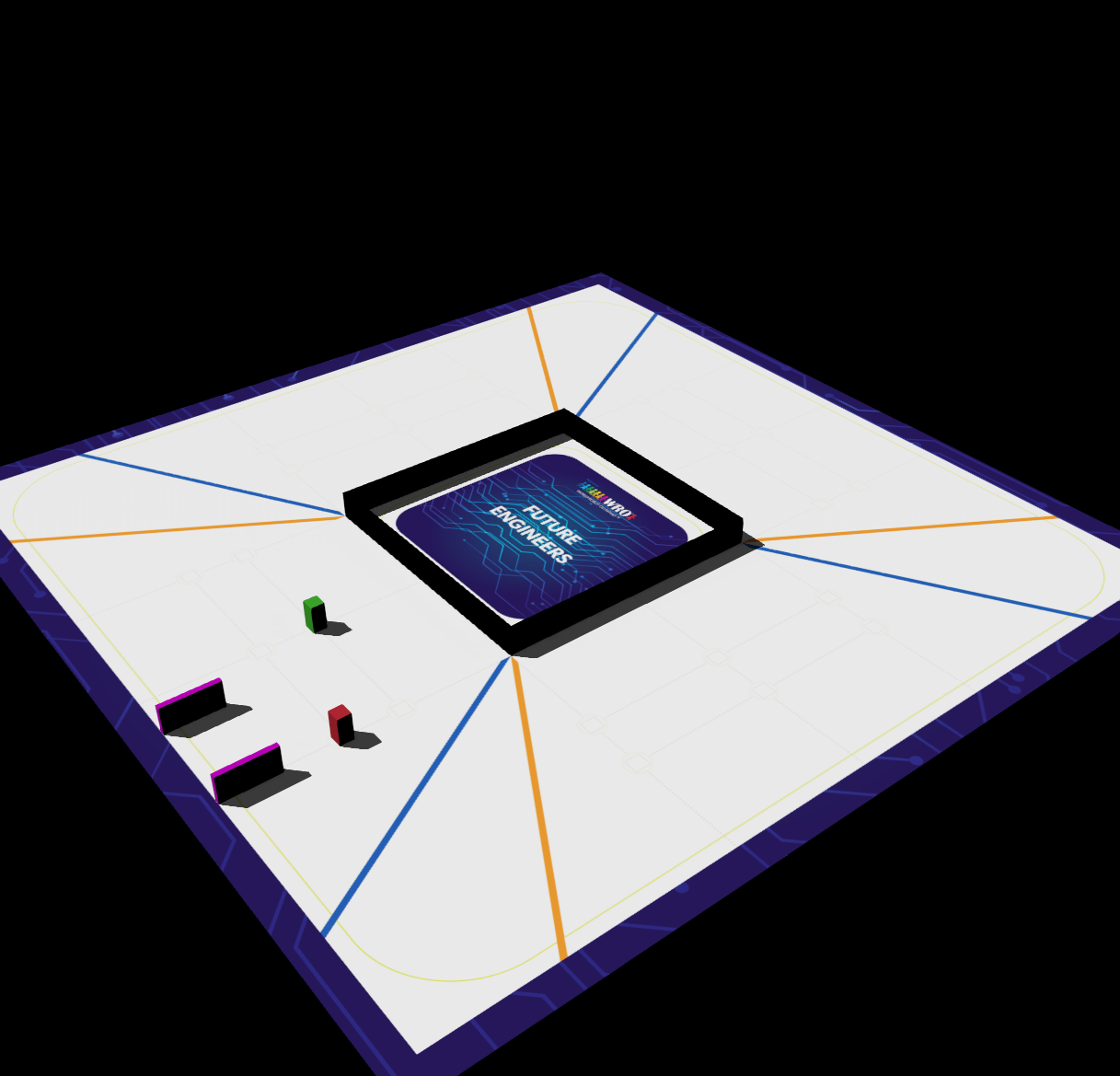
Initial Webots simulation environment used for conceptual development and algorithm testing
### 🏆 Performance Validation - **Open Challenge**: 16 seconds full score - [Watch Performance Video](../video/README.md#competition-performance-videos) - **Obstacle Challenge**: 35 seconds full score - [Watch Performance Video](../video/README.md#competition-performance-videos) - **Color Detection**: >95% accuracy under competition lighting - **Control Response**: <50ms latency from detection to actuation **Video Documentation**: Full performance demonstrations showcasing our robot's capabilities in both challenges are available in our [Video Documentation](../video/README.md), including: - 🎯 Autonomous navigation and speed control on dynamic tracks - 🚦 Traffic sign detection and obstacle avoidance - 🅿️ Optimal path planning and parallel parking maneuvers - ⚡ Smooth obstacle following at consistent distances ## 📁 File Structure & Dependencies ### Complete File List | File | Description | |------|-------------| | [`open.py`](open.py) | Open Challenge main control logic | | [`obstacle.py`](obstacle.py) | Obstacle Challenge with parking | | [`uart_slave.ino`](uart_slave.ino) | nRF52832 sensor firmware | | [`ANTi_wro_sim.wbt`](ANTi_wro_sim.wbt) | Webots simulation file (conceptual reference) | | [`/tests/`](tests/) | Development and validation test scripts | ### External Dependencies - **MicroPython Firmware** - STM32H747 compatible version - **Arduino nRF5 Board Support** - nRF52832 compilation ## 🚀 Deployment Instructions ### STM32H747 Setup (Camera MCU) 1. Connect via magnetic micro USB cable to computer 2. Copy MicroPython files to microcontroller filesystem: ```bash cp open.py /path/to/stm32/ cp obstacle.py /path/to/stm32/ ``` 3. Files execute automatically on startup from `main.py` ### nRF52832 Setup (Sensor MCU) 1. Open `uart_slave.ino` in Arduino IDE 2. Select nRF52832 board and proper port 3. Compile and upload via micro USB 4. Verify sensor data over Serial monitor ### System Startup 1. Power on LiPo Rider Plus switch 2. Wait for slave microcontroller ready signal 3. Press tactile start button to begin navigation 4. RGB LED indicates operational status ## ✅ Code Quality & Best Practices ### Software Engineering Principles - **Modular Design**: Separated vision, control, and sensor modules - **Comprehensive Documentation**: Inline comments and function descriptions - **Error Handling**: Robust exception handling with LED status indicators - **Resource Management**: Efficient memory usage and power management ### Performance Optimizations - **Minimal Memory Allocation**: Pre-allocated buffers and fixed-size arrays - **Efficient Algorithms**: Optimized blob detection and PID computations - **Timing Control**: Balanced control loop frequencies for stability - **Sensor Fusion**: Intelligent data weighting and validation ## 🔮 Future Improvements ### Planned Enhancements - **Machine Learning Integration**: Lightweight neural network for improved color classification if traditional thresholding proves insufficient - **Dynamic Path Planning**: A* algorithm implementation for optimal obstacle avoidance - **Adaptive Control**: Self-tuning PID parameters based on performance metrics - **Extended Simulation**: Enhanced Webots model for algorithm validation ### Research Directions - **Wireless Communication**: Real-time performance monitoring only for debugging process - **Advanced Sensor Fusion**: Kalman filtering for improved position estimation - **Energy Optimization**: Dynamic power management based on task requirements - **Custom Modular Sensor System**: Easy reconfiguration with existing sockets We challenged ourselves beyond the traditional competition rules to further develop our engineering knowledge across all aspects of the project, and we encourage future teams to continue this philosophy of pushing boundaries while maintaining comprehensive documentation. --- This comprehensive software documentation provides complete transparency into our algorithm design, implementation details, and engineering decision-making process. All code is structured for easy understanding and replication, meeting WRO Future Engineers competition requirements for detailed technical documentation. For hardware implementation: [Schemes Documentation](../schemes/README.md) For mechanical design: [Models Documentation](../models/README.md) For performance videos: [Video Documentation](../video/README.md) For additional resources: [Other Documentation](../other/README.md)