# IfcRelSpaceBoundary
The space boundary defines the physical or virtual delimiter of a space by the relationship _IfcRelSpaceBoundary_ to the surrounding elements.
* In the case of a physical space boundary, the placement and shape of the boundary may be given, and the building element, providing the boundary is referenced,
* In the case of a virtual space boundary, the placement and shape of the boundary may be given, and a virtual element is referenced.
The _IfcRelSpaceBoundary_ is defined as an objectified relationship that handles the element to space relationship by objectifying the relationship between an element and the space it bounds. It is given as a one-to-one relationship, but allows each element (including virtual elements and openings) to define many such relationships and each space to be defined by many such relationships.
Space boundaries are always defined as seen from the space. In general two basic types of space boundaries are distinguished:
* 1st level space boundary: defined as boundaries of the space, not taking into account any change in building element or spaces on the other side.
* 2nd level space boundary: defined as boundary taking any change in building element or spaces on the other side into account. It can be further distinguished into
* 2nd level type A: There is a space on the other side.
* 2nd level type B: There is a building element on the other side.
The exact definition of how space boundaries are broken down depends on the view definition, more detailed conventions on how space boundaries are decomposed can only be given at the domain or application type level.
* In an architectural or FM related view, a space boundary is defined totally from inside the space. This is a 1st level space boundary.
* In a thermal view, the decomposition of the space boundary depends on the material of the providing building element and the adjacent spaces behind. This is a 2nd level space boundary.
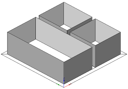
Figure 1 — Space boundary at first level
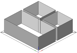
Figure 2 — Space boundary at second level
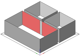
Figure 3 — Space boundary at second level type A
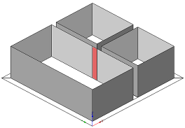
Figure 4 — Space boundary at second level type B
The differences between the 1st and 2nd level space boundaries are identified by:
* **1st level:** _IfcRoot.Name_ = "1stLevel" _IfcRoot.Description_ = NIL
* **2nd level:** _IfcRoot.Name_ = "2ndLevel" _IfcRoot.Description_ = "2a", or "2b"
Differentiation between physical and virtual space boundary is illustrated in Figure 5 and Figure 6.
As shown in Figure 5, if the _IfcRelSpaceBoundary_ is used to express a virtual boundary, the attribute _PhysicalOrVirtualBoundary_ has to be set to _VIRTUAL_. The attribute _RelatedBuildingElement_ shall point to an instance of _IfcVirtualElement_. If the correct location is of interest, the attribute _ConnectionGeometry_ is required.
> NOTE The connection geometry, either by a 2D curve or a 3D surface, is used to describe the portion of the "virtual wall" that separates the two spaces. All instances of _IfcRelSpaceBoundary_ given at the adjacent spaces share the same instance of _IfcVirtualElement_. Each instance of _IfcRelSpaceBoundary_ provides in addition the _ConnectionGeometry_ given within the local placement of each space.

As shown in Figure 6, if the _IfcRelSpaceBoundary_ is used to express a physical boundary between two spaces, the attribute _PhysicalOrVirtualBoundary_ has to be set to _PHYSICAL_. The attribute _RelatedBuildingElement_ has to be given and points to the element providing the space boundary. The attribute _ConnectionGeometry_ may be inserted, in this case it describes the physical space boundary geometrically, or it may be omitted; in that case it describes a physical space boundary logically.

The _IfcRelSpaceBoundary_ may have geometry attached. If geometry is not attached, the relationship between space and building element is handled only on a logical level. If geometry is attached, it is given within the local coordinate systems of the space.
> NOTE The attributes _CurveOnRelatingElement_ at _IfcConnectionCurveGeometry_ or _SurfaceOnRelatingElement_ at _IfcConnectionSurfaceGeometry_ provide the geometry within the local coordinate system of the _IfcSpace_, whereas the attributes _CurveOnRelatedElement_ at _IfcConnectionCurveGeometry_ or _SurfaceOnRelatedElement_ at _IfcConnectionSurfaceGeometry_ provide the geometry within the local coordinate system of the subtype of _IfcElement_.
The geometric representation (through the _ConnectionGeometry_ attribute) is defined using either 2D curve geometry or 3D surface geometry for space boundaries.
* 1st level space boundary:
* only connection geometry for related space shall be provided
* only surface connection geometry shall be provided
* only the following surface representations are supported:
* _IfcSurfaceOfLinearExtrusion_
* _IfcCurveBoundedPlane_
* _IfcCurveBoundedSurface_
* _IfcFaceBasedSurfaceModel_
* 2nd level space boundary:
* only connection geometry for related space shall be provided
* only surface connection geometry shall be provided
* only the following surface representations are supported:
* _IfcCurveBoundedPlane_ with restrictions to have polygonal boundaries only
* _IfcFaceBasedSurfaceModel_
**Surface connection geometry**
The following constraints apply to the surface connection geometry representation:
* planar boundaries:
* _IfcSurfaceOfLinearExtrusion_ defined by a _SweptCurve_ being an _IfcArbitraryOpenProfileDef_ with straight segments, or
* _IfcCurveBoundedPlane_
* curved boundaries
* _IfcSurfaceOfLinearExtrusion_ defined by a _SweptCurve_ being an _IfcArbitraryOpenProfileDef_ with curves segments, or
* _IfcCurveBoundedSurface_ with a _BasisSurface_ being a non planar surface, such as _IfcCylindricalSurface_, or
* _IfcFaceBasedSurfaceModel_ if already faceted.
**Curve connection geometry**
The following constraints apply to the 2D curve representation:
* Curve: _IfcPolyline_, _IfcTrimmedCurve_ or _IfcCompositeCurve_
> HISTORY New entity in IFC1.5, the entity has been modified in IFC2x.
{ .change-ifc2x}
> IFC2x CHANGE The data type of the attribute _RelatedBuildingElement_ has been changed from _IfcBuildingElement_ to its supertype _IfcElement_. The data type of the attribute _ConnectionGeometry_ has been changed from _IfcConnectionSurfaceGeometry_ to its supertype _IfcConnectionGeometry_.
{ .change-ifc2x4}
> IFC4 CHANGE The attribute _RelatedBuildingElement_ has been made mandatory. For virtual boundaries the reference to _IfcVirtualElement_ is now mandatory.
## Attributes
### RelatingSpace
Reference to one space that is delimited by this boundary.
### RelatedBuildingElement
Reference to the Element that defines the Space Boundaries.
> IFC2x CHANGE The data type has been changed from _IfcBuildingElement_ to _IfcElement_ with upward compatibility for file based exchange.
> IFC4 CHANGE The attribute has been changed to be mandatory.
### ConnectionGeometry
Physical representation of the space boundary. Provided as a curve or surface given within the LCS of the space.
{ .change-ifc2x}
> IFC2x CHANGE The data type has been changed from _IfcConnectionSurfaceGeometry_ to _IfcConnectionGeometry_ with upward compatibility for file based exchange.
### PhysicalOrVirtualBoundary
Defines whether the Space Boundary is _PHYISICAL_ or _VIRTUAL_.
### InternalOrExternalBoundary
Defines whether the Space Boundary is INTERNAL, or EXTERNAL, i.e. adjacent to open space that can be a partially enclosed space, such as terrace.
## Formal Propositions
### CorrectPhysOrVirt
If the space boundary is physical, it shall be provided by an element (i.e. excluding a virtual element). If the space boundary is virtual, it shall either have a virtual element or an opening providing the space boundary. If the space boundary _PhysicalOrVirtualBoundary_ attribute is not defined, no restrictions are imposed.
{ .change-ifc2x4}
> IFC4 CHANGE Where rule corrected to accept an _IfcOpeningElement_ for a virtual space boundary.