# Embedded network programming guide
[](https://opensource.org/licenses/MIT)
This guide is written for embedded developers who work on connected products.
That includes microcontroller based systems that operate in bare metal or
RTOS mode, as well as microprocessor based systems which run embedded Linux.
## Prerequisites
All fundamental concepts are explained in details, so the guide should be
understood by a reader with no prior networking knowledge.
A reader is expected to be familiar with microcontroller C programming - for
that matter, I recommend reading my [bare metal programming
guide](https://github.com/cpq/bare-metal-programming-guide). I will be using
Ethernet-enabled Nucleo-H743ZI board throughout this guide. Examples for other
architectures are summarized in a table below - this list will expand with
time. Regardless, for the best experience I recommend Nucleo-H743ZI to get the
most from this guide: [buy it on
Mouser](https://www.mouser.ie/ProductDetail/STMicroelectronics/NUCLEO-H743ZI2?qs=lYGu3FyN48cfUB5JhJTnlw%3D%3D).
## Network stack explained
### Network frame structure
When any two devices communicate, they exchange discrete pieces of data called
frames. Frames can be sent over the wire (like Ethernet) or over the air (like
WiFi or Cellular). Frames differ in size, and typically range from couple of
dozen bytes to a 1.5Kb. Each frame consists of a sequence of protocol headers
followed by user data:

The purpose of the headers is as follows:
**MAC (Media Access Control) header** is only 3 fields: destination MAC
address, source MAC addresses, and an upper level protocol. MAC addresses are
6-byte unique addresses of the network cards, e.g. `42:ef:15:c8:29:a1`.
Protocol is usually 0x800, which means that the next header is IP. MAC header
handles addressing in the local network (LAN).
**IP (Internet Protocol) header** has many fields, but the most important are:
destination IP address, source IP address, and upper level protocol. IP
addresses are 4-bytes, e.g. `209.85.202.102`, and they identify a machine
on the Internet, so their purpose is similar to phone numbers. The upper level
protocol is usually 6 (TCP) or 17 (UDP). IP header handles global addressing.
**TCP or UDP header** has many fields, but the most important are destination
port and source ports. On one device, there can be many network applications,
for example, many open tabs in a browser. Port number identifies
an application.
**Application protocol** depends on the target application. For example, there
are servers on the Internet that can tell an accurate current time. If you want
to send data to those servers, the application protocol must SNTP (Simple
Network Time Protocol). If you want to talk to a web server, the protocol must
be HTTP. There are other protocols, like DNS, MQTT, etc, each having their own
headers, followed by the application data.
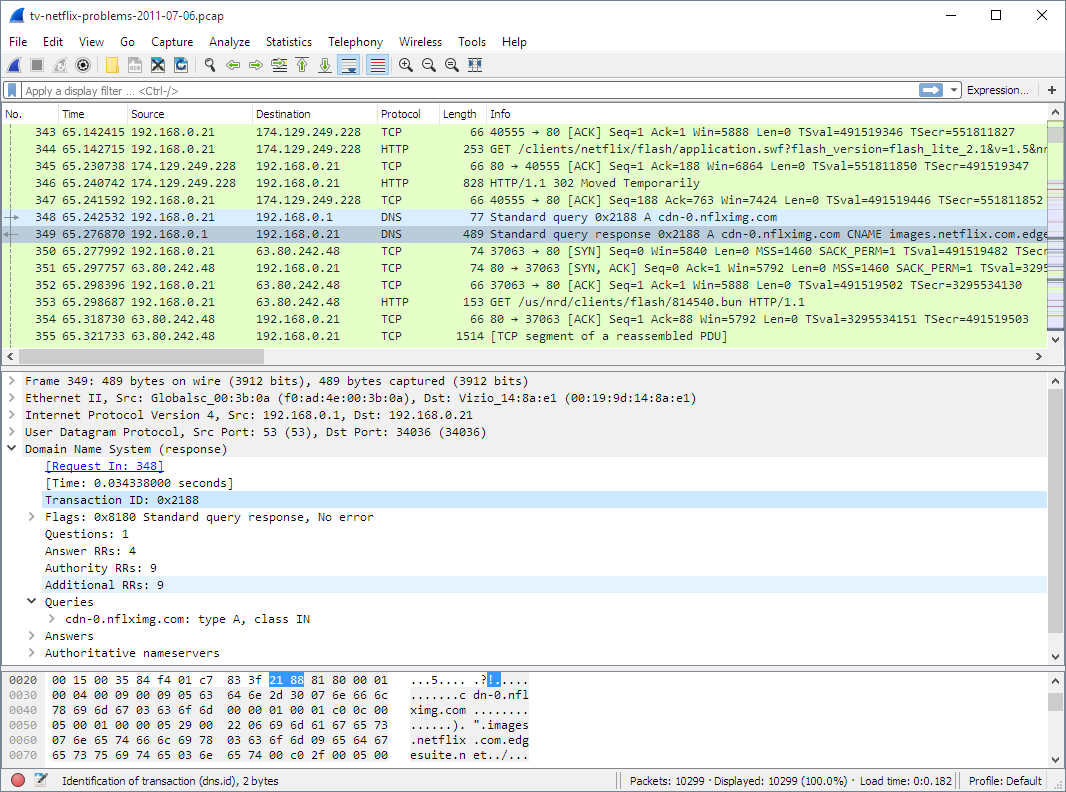
Install [Wireshark](https://www.wireshark.org/) tool to observe network
frames. It helps to identify issues quickly, and looks like this:
The structure of a frame described above, makes it possible to accurately
deliver a frame to the correct device and application over the Internet. When a
frame arrives to a device, a software that handles that frame (a network
stack), is organised in four layers.
### Network stack architecture

Layer 1: **Driver layer**, only reads and writes frames from/to network hardware
Layer 2: **TCP/IP stack**, parses protocol headers and handles IP and TCP/UDP
Layer 3: **Network Library**, parses application protocols like DNS, MQTT, HTTP
Layer 4: **Application** - Web dashboard, smart sensor, etc
### DNS request example
Let's provide an example. In order to show your this guide on the Github, your
browser first needs to find out the IP address of the Github's machine. For
that, it should make a DNS (Domain Name System) request to one of the DNS
servers. Here's how your browser and the network stack work for that case:

**1.** Your browser (an application) asks from the lower layer (library), "what
IP address `github.com` has?". The lower layer (layer 3, a library layer - in
this case, it is a C library) provides an API function `gethostbyname()`
that returns an IP address for a given host name. So everything said below,
essentially describes how `gethostbyname()` works.
**2.** The library layer gets the name `github.com` and creates a properly
formatted, binary DNS request: `struct dns_request`. Then it calls an API
function `sendto()` provided by the TCP/IP stack layer (layer 2), to send that
request over UDP to the DNS server. The IP of the DNS server is known to the library
from the workstation settings. The UDP port is also known - port 53, a standard
port for DNS.
**3.** The TCP/IP stack's `sendto()` function receives a chunk of data to send.
it contains DNS request, but `sendto()` does not know that and does not care
about that. All it knows is that this is the piece of user data that needs to
be delievered over UDP to a certain IP address (IP address of a DNS server) on
port 53. Hence TCP/IP stack prepends UDP, IP, and MAC headers
to the user data to form a frame. Then it calls API function `send_frame()`
provided by the driver layer, layer 1.
**4.** A driver's `send_frame()` function transmits a frame over the wire or
over the air, the frame travels to the destination DNS server. A chain of
Internet routers pass that frame from one to another, until a frame finally hits
DNS server's network card.
**5.** A network card on the DNS server gets a frame and generates a hardware
interrupt, invoking interrupt handler. It is part of a driver - layer 1. It
calls a function `recv_frame()` that reads a frame from the card, and passes
it up by calling `ethernet_input()` function provided by the TCP/IP stack
**6.** TCP/IP stack parses the frame, and finds out that it is for the UDP port
53, which is a DNS port number. TCP/IP stack finds an application that listens
on UDP port 53, which is a DNS server application, and wakes up its `recv()`
call. So, DNS server application that is blocked on a `recv()` call, receives
a chunk of data - which is a DNS request. A library routine parses that request
by extracting a host name, and passes that parsed DNS request to the application.
**7.** A DNS server application receives DNS request: "someone wants an
IP address for `github.com`". Then the application layer looks at its
configuration, figures out "Oh, it's me who is responsible for the github.com
domain, and this is the IP address I should respond with". The application
extracts an IP address from the configuration, and calls a library function
"get this IP, wrap into a DNS response, and send back". And the response
travels all the way back in the reverse order.
### BSD socket API
The communication between layers are done via a function calls. So, each
layer has its own API, which upper and lower levels can call. They are not
standardized, so each implementation provides their own set of functions.
However, on OSes like Windows/Mac/Linux/UNIX, a driver and TCP/IP layers are
implemented in kernel, and TCP/IP layer provides a standard API to the
userland which is called a "BSD socket API":

This is done becase kernel code does not implement application level protocols
like MQTT, HTTP, etc, - so it let's user application to implement them in
userland. So, a library layer and an application layer reside in userland.
Some library level routines are provided in C standard library, like
DNS resolution function `gethostbyname()`, but that DNS library functions
are probably the only ones that are provided by OS. For other protocols,
many libraries exist that provide HTTP, MQTT, Websocket, SSH, API. Some
applications don't use any external libraries: they use BSD socket API
directly and implement library layer manually. Usually that is done when
application decides to use some custom protocol.
Embedded systems very often use TCP/IP stacks that provide the same BSD API as
mainstream OSes do. For example, lwIP (LightWeight IP) TCP/IP stack, Keil's MDK
TCP/IP stack, Zephyr RTOS TCP/IP stack - all provide BSD socket API. Thus let's
review the most important BSD API stack functions:
- `socket(protocol)` - creates a connection descriptor and assigns an integer ID for it, a "socket"
- `bind(sock, addr)` - assigns a local IP:PORT for a listening socket
- `accept(sock, addr)` - creates a new socket, assigns local IP:PORT
and remote IP:PORT (incoming)
- `connect(sock, addr)` - assigns local IP:PORT and remote IP:PORT for
a socket (outgoing)
- `send(sock, buf, len)` - sends data
- `recv(sock, buf, len)` - receives data
- `close(sock)` - closes a socket
Some implementations do not implement BSD socket API, and there are perfectly
good reasons for that. Examples for such implementation is lwIP raw API,
and Mongoose Library.
### TCP echo server implemented with socket API
Let me demonstrate the two approaches (using socket and non-socket API) on a simple
TCP echo server example. TCP echo server is a simple application that
listens on a TCP port, receives data from clients that connect to that port,
and writes (echoes) that data back to the client. That means, this application
does not use any application protocol on top of TCP, thus it does not need
a library layer. Let's see how this application would look like written
with a BSD socket API. First, a TCP listener should bind to a port, and
for every connected client, spawn a new thread that would handle it. A thread
function that sends/receives data, looks something like this:
```c
void handle_new_connection(int sock) {
char buf[20];
for (;;) {
ssize_t len = recv(sock, buf, sizeof(buf), 0); // Receive data from remote
if (len <= 0) break; // Error! Exit the loop
send(sock, buf, len); // Success. Echo data back
}
close(sock); // Close socket, stop thread
}
```
Note that `recv()` function blocks until it receives some data from the client.
Then, `send()` also blocks until is sends requested data back to the client.
That means that this code cannot run in a bare metal implementation, because
`recv()` would block the whole firmware. For this to work, an RTOS is required.
A TCP/IP stack should run in a separate RTOS task, and both `send()` and
`recv()` functions are implemented using an RTOS queue API, providing a
blocking way to pass data from one task to another. Overall, this is how an
embedded receive path looks like with socket API:

The `send()` part would work in the reverse direction. Note that this approach
requires TCP/IP stack implement data buffering for each socket, because
an application consumes received data not immediately, but after some time,
when RTOS queue delivers data. Note that using non-blocking sockets and
`select()/poll()` changes things that instead of many application tasks,
there is only one application task, but the mechanism stays the same.
Therefore this approach with socket API has
the following major characteristics:
1. It uses queues for exchanging data between TCP/IP stack and
application tasks, which consumes both RAM and time
2. TCP/IP stack buffers received and sent data for each socket. Note that
the app/library layer may also buffer data - for example, buffering a full
HTTP request before it can be processed. So the same data goes through
two buffering "zones" - TCP/IP stack, and library/app
That means, socket API implementation takes extra time for data to be processed,
and takes extra RAM for double-buffering in the TCP/IP stack.
### TCP echo server with non-socket (callback) API
Now let's see how the same approach works without BSD socket API. Several
implementations, including lwIP and Mongoose Library, provide callback API to
the TCP/IP stack. Here is how TCP echo server would look like written using
Mongoose API:
```c
// This callback function is called for various network events, MG_EV_*
void event_handler(struct mg_connection *c, int ev, void *ev_data, void *fn_data) {
if (ev == MG_EV_READ) {
// MG_EV_READ means that new data got buffered in the c->recv buffer
mg_send(c, c->recv.buf, c->recv.len); // Send back the data we received
c->recv.len = 0; // Discard received data
}
}
```
In this case, all functions are non-blocking, that means that data exchange
between TCP/IP stack and an app can be implemented via direct function calls.
This is how receive path looks like:

As you can see, in this case TCP/IP stack provides a callback API which
a library or application layer can use to receive data directly. No need
to send it over a queue. A library/app layer can buffer data, and that's
the only place where buffering takes place. This approach wins for
memory usage and performance. A firmware developer should use
a proprietary callback API instead of BSD socket API.
lwIP TCP/IP stack, for example, provides both socket and non-socket (raw) API,
and raw API is more efficient in terms of RAM and performance. However
developers rarely use raw API, because it is not trivial to understand and use
compared to the socket API. The API of the Mongoose Library shown above
is designed to be simple and easy to understand. API design can make things
very easy or very difficult, so it is important to have a good API.
## Implementing layers 1,2,3 - making ping work
### Development environment and tools
Now let's make our hands dirty and implement a working network stack on
a microcontroller board. I will be using
[Mongoose Library](https://github.com/cesanta/mongoose) for all examples
further on, for the following reasons:
- Mongoose is very easy to integrate: just by copying two files,
[mongoose.c]() and [mongoose.h]()
- Mongoose has a built-in drivers, TCP/IP stack, HTTP/MQTT/Websocket library,
and TLS 1.3 all in one, so it does not need any other software to create
a network-enabled application
- Mongoose provides a simple, polished callback API designed specifically
for embedded developers
The diagram below shows Mongoose architecture. As you can see, Mongoose can
use external TCP/IP stack and TLS libraries, as well as built-in ones. In the
following example, we are going to use only a built-in functionality, so we
won't need any other software.

All source code in this guide is MIT licensed, however Mongoose
is licensed under a dual GPLv2/commercial license.
I will be using a Nucleo board from ST Microelectronics, and there are several choices for the
development environment:
- Use Cube IDE provided by ST: [install Cube](https://www.st.com/en/development-tools/stm32cubeide.html)
- Use Keil from ARM: [install Keil](https://www.keil.com/)
- Use make + GCC compiler, no IDE: follow [this guide](https://mongoose.ws/documentation/tutorials/tools/)
Here, I am going to use Cube IDE. In the templates, however, both Keil and
make examples are provided, too. So, in order to proceed, install Cube IDE
on your workstation, and plug in Nucleo board to your workstation.
### Skeleton firmware
Note: this and the following sections has a Youtube helper video recorded:
https://www.youtube.com/watch?v=lKYM4b8TZts
The first step would be to create a minimal, skeleton firmware that does
nothing but logs messages to the serial console. Once we've done that, we'll
add networking functionality on top of it. The table below summarises
peripherals for various boards:
| Board | UART, TX, RX | Ethernet | LED |
| ---------------- | --------------- | ------------------------------------- | -------------- |
| STM32H747I-DISCO | USART1, A9, A10 | A1, A2, A7, C1, C4, C5, G12, G11, G13 | I12, I13, I14 |
| STM32H573I-DK | USART1, A9, A10 | A1, A2, A7, C1, C4, C5, G12, G11, G13 | I8, I9, F1 |
| Nucleo-H743ZI | USART3, D8, D9 | A1, A2, A7, C1, C4, C5, B13, G11, G13 | B0, E1, B14 |
| Nucleo-H723ZG | USART3, D8, D9 | A1, A2, A7, C1, C4, C5, B13, G11, G13 | B0, E1, B14 |
| Nucleo-H563ZI | USART3, D8, D9 | A1, A2, A7, C1, C4, C5, B15, G11, G13 | B0, F4, G4 |
| Nucleo-F746ZG | USART3, D8, D9 | A1, A2, A7, C1, C4, C5, B13, G11, G13 | B0, B7, B14 |
| Nucleo-F756ZG | USART3, D8, D9 | A1, A2, A7, C1, C4, C5, B13, G11, G13 | B0, B7, B14 |
| Nucleo-F429ZI | USART3, D8, D9 | A1, A2, A7, C1, C4, C5, B13, G11, G13 | B0, B7, B14 |
**Step 1.** Start Cube IDE. Choose File / New / STM32 project
**Step 2.** In the "part number" field, type the microcontroller name,
for example "H743ZI". That should narrow down
the MCU/MPU list selection in the bottom right corner to a single row.
Click on the row at the bottom right, then click on the Next button
**Step 3.** In the project name field, type any name, click Finish.
Answer "yes" if a pop-up dialog appears
**Step 4.** A configuration window appears. Click on Clock configuration tab.
Find a field with a system clock value. Type the maximum value, hit enter,
answer "yes" on auto-configuration question, wait until configured
**Step 5.** Switch to the Pinout tab, Connectivity, then enable the UART controller
and pins (see table above), choose "Asynchronous mode"
**Step 6.** Click on Connectivity / ETH, Choose Mode / RMII, verify that the
configured pins are like in the table above - if not, change pins
**Step 7.** Lookup the LED GPIO from the peripherals table, and configure it
for output. Click on the corresponding pin, select "GPIO output"
**Step 8.** Click Ctrl+S to save the configuration. This generates the code
and opens main.c file
**Step 9.** Navigate to the `main()` function and add some logging to the
`while` loop. Make sure to insert your code between the "USER CODE" comments,
because CubeIDE will preserve it during code regeneration:
```c
/* USER CODE BEGIN WHILE */
while (1)
{
printf("Tick: %lu\r\n", HAL_GetTick());
HAL_Delay(500);
```
**Step 10.** Redirect `printf()` to the UART. Note the UART global variable
generated by Cube at the beginning of `main.c` - typically it is
`UART_HandleTypeDef huart3;`. Copy it, open `syscalls.c`, find function
`_write()` and modify it the following way :
```c
#include "main.h"
__attribute__((weak)) int _write(int file, char *ptr, int len) {
if (file == 1 || file == 2) {
extern UART_HandleTypeDef huart3;
HAL_UART_Transmit(&huart3, (unsigned char *) ptr, len, 999);
}
return len;
}
```
**Step 11.** Click on "Run" button to flash this firmware to the board.
**Step 12.** Attach a serial monitor tool (e.g. putty on Windows, or
`cu -l COMPORT -s 115200` on Mac/Linux) and observe UART logs:
```
Tick: 90358
Tick: 90860
...
```
Our skeleton firmware is ready!
### Integrate Mongoose
Now it's time to implement a functional TCP/IP stack. We'll use Mongoose
Library for that. To integrate it, we need to copy two files into our source tree.
**Step 1**. Open https://github.com/cesanta/mongoose in your browser, click on "mongoose.h". Click on "Raw" button, and copy file contents into clipboard.
In the CubeIDE, right click on Core/Inc, choose New/File in the menu, type
"mongoose.h", paste the file content and save.
**Step 2**. Repeat for "mongoose.c". On Github, copy `mongoose.c` contents
to the clipboard. In the CubeIDE, right click on Core/Src, choose New/File
in the menu, type "mongoose.c", paste the file content and save.
**Step 3**. Right click on Core/Inc, choose New/File in the menu, type
"mongoose_custom.h", and paste the following contents:
```c
#pragma once
// See https://mongoose.ws/documentation/#build-options
#define MG_ARCH MG_ARCH_NEWLIB
#define MG_ENABLE_TCPIP 1 // Enables built-in TCP/IP stack
#define MG_ENABLE_CUSTOM_MILLIS 1 // We must implement mg_millis()
#define MG_ENABLE_DRIVER_STM32H 1 // On STM32Fxx series, use MG_ENABLE_DRIVER_STM32F
```
**Step 4**. Implement Layer 1 (driver), 2 (TCP/IP stack) and 3 (library) in
our code. Open `main.c`. Add `#include "mongoose.h"` at the top:
```c
/* USER CODE BEGIN Includes */
#include "mongoose.h"
/* USER CODE END Includes */
```
**Step 5**. Before `main()`, define function `mg_millis()` that returns
an uptime in milliseconds. It will be used by Mongoose Library for the time
keeping:
```c
/* USER CODE BEGIN 0 */
uint64_t mg_millis(void) {
return HAL_GetTick();
}
/* USER CODE END 0 */
```
**Step 6**. Navigate to `main()` function and change the code around `while`
loop this way:
```c
/* USER CODE BEGIN WHILE */
struct mg_mgr mgr;
mg_mgr_init(&mgr);
mg_log_set(MG_LL_DEBUG);
// On STM32Fxx, use _stm32f suffix instead of _stm32h
struct mg_tcpip_driver_stm32h_data driver_data = {.mdc_cr = 4};
struct mg_tcpip_if mif = {.mac = {2, 3, 4, 5, 6, 7},
// Uncomment below for static configuration:
// .ip = mg_htonl(MG_U32(192, 168, 0, 223)),
// .mask = mg_htonl(MG_U32(255, 255, 255, 0)),
// .gw = mg_htonl(MG_U32(192, 168, 0, 1)),
.driver = &mg_tcpip_driver_stm32h,
.driver_data = &driver_data};
NVIC_EnableIRQ(ETH_IRQn);
mg_tcpip_init(&mgr, &mif);
while (1) {
mg_mgr_poll(&mgr, 0);
/* USER CODE END WHILE */
```
**Step 7**. Connect your board to the Ethernet. Flash firmware. In the serial
log, you should see something like this:
```
bb8 3 mongoose.c:14914:mg_tcpip_driv Link is 100M full-duplex
bbd 1 mongoose.c:4676:onstatechange Link up
bc2 3 mongoose.c:4776:tx_dhcp_discov DHCP discover sent. Our MAC: 02:03:04:05:06:07
c0e 3 mongoose.c:4755:tx_dhcp_reques DHCP req sent
c13 2 mongoose.c:4882:rx_dhcp_client Lease: 86400 sec (86403)
c19 2 mongoose.c:4671:onstatechange READY, IP: 192.168.2.76
c1e 2 mongoose.c:4672:onstatechange GW: 192.168.2.1
c24 2 mongoose.c:4673:onstatechange MAC: 02:03:04:05:06:07
```
If you don't, and see DHCP requests message like this:
```
130b0 3 mongoose.c:4776:tx_dhcp_discov DHCP discover sent. Our MAC: 02:03:04:05:06:07
13498 3 mongoose.c:4776:tx_dhcp_discov DHCP discover sent. Our MAC: 02:03:04:05:06:07
...
```
The most common cause for this is you have your Ethernet pins wrong. Click
on the `.ioc` file, go to the Ethernet configuration, and double-check the
Ethernet pins against the table above.
**Step 8**. Open terminal/command prompt, and run a `ping` command against
the IP address of your board:
```sh
$ ping 192.168.2.76
PING 192.168.2.76 (192.168.2.76): 56 data bytes
64 bytes from 192.168.2.76: icmp_seq=0 ttl=64 time=9.515 ms
64 bytes from 192.168.2.76: icmp_seq=1 ttl=64 time=1.012 ms
```
Now, we have a functional network stack running on our board. Layers 1,2,3
are implemented. It's time to create an application - a simple web server,
hence implement layer 4.
## Implementing layer 4 - a simple web server
Let's add a very simple web server that responds "ok" to any HTTP request.
**Step 1**. After the `mg_tcpip_init()` call, add this line that creates HTTP listener
with `fn` event handler function:
```c
mg_http_listen(&mgr, "http://0.0.0.0:80", fn, NULL);
```
**Step 2**. Before the `mg_millis()` function, add the `fn` event handler function:
```c
static void fn(struct mg_connection *c, int ev, void *ev_data) {
if (ev == MG_EV_HTTP_MSG) {
struct mg_http_message *hm = ev_data; // Parsed HTTP request
mg_http_reply(c, 200, "", "ok\r\n");
}
}
```
That's it! Flash the firmware. Open your browser, type board's IP address and
see the "ok" message.
Note that the [mg_http_reply()](https://mongoose.ws/documentation/#mg_http_reply)
function is very versatile: it cat create formatted output, like printf
on steroids. See [mg_snprintf()](https://mongoose.ws/documentation/#mg_snprintf-mg_vsnprintf)
for the supported format specifiers: most of them are standard printf, but
there are two non-standard: `%m` and `%M` that accept custom formatting
function - and this way, Mongoose's printf can print virtually anything.
For example, JSON strings. That said, with the aid of `mg_http_reply()`,
we can generate HTTP responses of arbitrary complexity.
So, how the whole flow works? Here is how. When a browser connects,
an Ethernet IRQ handler (layer 1) kicks in. It is defined by Mongoose, and activated by
the `#define MG_ENABLE_DRIVER_STM32H 1` line in the `mongoose_custom.h`: [ETH_IRQHandler](https://github.com/cesanta/mongoose/blob/68e2cd9b296733c9aea8b3401ab946dd25de9c0e/src/drivers/stm32h.c#L252). Other environments, like CubeIDE, implement `ETH_IRQHandler`
and activate it when you select "Enable Ethernet interrupt" in the Ethernet
configuration. To avoid clash with Cube, we did not activate Ethernet interrupt.
IRQ handler reads frame from the DMA, copies that frame to the Mongoose's
[receive queue](https://github.com/cesanta/mongoose/blob/68e2cd9b296733c9aea8b3401ab946dd25de9c0e/src/net_builtin.h#L30), and exits.
That receive queue is special, it is a thread-safe
single-producer-single-consumer non-blocking queue, so an IRQ handler, being
executed in any context, can safely write to it.
The `mg_poll()` function in the infinite `while()` loop constantly
verifies, whether we receive any data in the receive queue. When it detects
a frame in the receive queue, it extracts that frame, passes it on to the
[mg_tcp_rx()](https://github.com/cesanta/mongoose/blob/68e2cd9b296733c9aea8b3401ab946dd25de9c0e/src/net_builtin.c#L800) function - which is an etry point to the layer 2 TCP/IP stack.
That `mg_tcp_rx()` function parses headers, starting from Ethernet header,
and when it detects that a received frame belongs to one of the Mongoose
TCP or UDP connections, it copies frame payload to the connection's `c->recv`
buffer and [calls `MG_EV_READ` event](https://github.com/cesanta/mongoose/blob/68e2cd9b296733c9aea8b3401ab946dd25de9c0e/src/net_builtin.c#L687).
At this point, processing leaves layer 2 and enters layer 3 - a library layer.
Mongoose's HTTP event handlers catches `MG_EV_READ`, parses received data,
and when it detects that the full HTTP message is buffered, it [sends the
`MG_EV_HTTP_MSG` with parsed HTTP message](https://github.com/cesanta/mongoose/blob/68e2cd9b296733c9aea8b3401ab946dd25de9c0e/src/http.c#L1033) to the application - layer 4.
And this is where our event handler function `fn()` gets called. Our code is
simple - we catch `MG_EV_HTTP_MSG` event, and use Mongoose's API function
`mg_http_reply()` to craft a simple HTTP response:
```
HTTP/1.1 200 OK
Content-Length: 4
ok
```
This response goes to Mongoose's `c->send` output buffer, and `mg_mgr_poll()`
drains that data to the browser, [splitting the response by frames](https://github.com/cesanta/mongoose/blob/68e2cd9b296733c9aea8b3401ab946dd25de9c0e/src/net_builtin.c#L587-L588)
in layer 2, then passing to the layer 1. An Ethernet driver's output function [mg_tcpip_driver_stm32h_tx()](https://github.com/cesanta/mongoose/blob/68e2cd9b296733c9aea8b3401ab946dd25de9c0e/src/drivers/stm32h.c#L208) sends those frames back to the browser.
This is how Mongoose Library works.
Other implementations, like Zephyr, Amazon FreeRTOS-TCP, Azure, lwIP, work in
a similar way. They implement BSD socket layer so it is a bit more complicated
cause it includes an extra socket layer, but the principle is the same.
## Implementing Web UI
Using `mg_http_reply()` function is nice, but it's very good for creating
custom responses. It is not suitable for serving files. And the standard way
to build a web UI is to split it into two parts:
- a static part, which consists of directory with `index.html`, CSS,
JavaScript and image files,
- a dynamic part, which serves REST API
So instead of using `mg_http_reply()` and responding with "ok" to any request,
let's create a directory with `index.html` file and serve that directory.
Mongoose has API function `mg_http_serve_dir()` for that. Let's change the
event handler code to use that function:
```c
static void fn(struct mg_connection *c, int ev, void *ev_data) {
if (ev == MG_EV_HTTP_MSG) {
struct mg_http_message *hm = ev_data; // Parsed HTTP request
struct mg_http_serve_opts opts = {.root_dir = "/web_root"};
mg_http_serve_dir(c, hm, &opts);
}
}
```
Build it and get build error "undefined reference to 'mkdir'". This is because
`mg_http_serve_dir()` function tries to use a default POSIX filesystem to
read files from directory `/web_root`, and our firmware does not have support
for the POSIX filesystem.
What are the possibilities here? First, we can implement POSIX filesystem,
by using an internal or external flash memory. Then we can copy our `web_root`
directory there, and our code will start to work. This is the hard way.
The easy way is to use a so-called embedded filesystem, by
transforming all files in the web directory into C arrays, and compiling them
into the firmware binary. This way, all UI files are simply hardcoded into the
firmware binary, and there is no need to implement a "real" filesystem:
**Step 1**. Tell `mg_http_serve_dir()` to use packed filesystem:
```c
struct mg_http_serve_opts opts = {.root_dir = "/web_root", .fs = &mg_fs_packed};
```
**Step 2**. Enable packed filesystem, and disable POSIX filesystem in `mongoose_custom.h`:
```c
#define MG_ENABLE_PACKED_FS 1
#define MG_ENABLE_POSIX_FS 0
```
**Step 3**. Create a new file `Core/Src/packed_fs.c`. Go to https://mongoose.ws/ui-pack/,
review UI files. Copy/paste the contents of generated `packed_fs.c`, save.
Build the firmware - and now it should build with no errors.
Let's review what that UI packer does. As you can see, it has 3 files, which
implement a very simple Web UI with LED control. The `index.html` file
loads `main.js` file, which defines a button click handler. When a button
gets clicked, it makes a request to the `api/led/toggle` URL, and when
than request completes, it makes another request to `api/led/get` URL,
and sets the status span element to the result of the request.
The tool has a preview window, and if any of the files are changed,
it automatically refreshes preview and regenerates packed_fs.c. The packed_fs.c
is a simple C file, which contains three C arrays, representing three files
we have, and two helper functions `mg_unlist()` and `mg_unpack()`, used by
Mongoose:
- the `mg_unlist()` function allows to scan the whole "filesystem" and get names of every file,
- the `mg_unpack()` function returns file contents, size, and modification time for a given file.
Mongoose provides a command line utility [pack.c](https://github.com/cesanta/mongoose/blob/master/test/pack.c)
to generate `packed_fs.c` automatically during the build. The example of that
is a [Makefile](https://github.com/cesanta/mongoose/blob/f883504d2d44d24cae1ca6c9f88ce780ab36f59b/examples/device-dashboard/Makefile#L38-L43)
for device dashboard example in Mongoose repository, which not only packs,
but also compresses files to minimise their size. But here, we'll use the
web tool because it is visual and makes it easy to understand the flow.
The static HTML is extremely simple. There 3 files: `index.html`, `style.css`
and `main.js`. The `index.html` references, or loads, the other two:
**index.html:**
```html
My Device
LED status:0
```
**style.css:**
```css
.main { margin: 1em; }
#status { display: inline-block; width: 2em; }
```
The Javascript code in the `main.js` file installs an event handler on button
click, so when a user clicks on a button, JS code makes HTTP requests -
I'll comment down below how it all works together:
**main.js:**
```javascript
var getStatus = ev => fetch('api/led/get')
.then(r => r.json())
.then(r => { document.getElementById('status').innerHTML = r; });
var toggle = ev => fetch('api/led/toggle')
.then(r => getStatus());
document.getElementById('btn').onclick = toggle;
```
Now, let's flash the firmware. Go to the IP address in the browser - and
now we see the Web UI with a button! Click on the button, and see that nothing
happens! The LED does not turn on and off. Open developer tools and see that
on every click, a browser makes "toggle" and "get" requests which return 404
error - not found. Let's implement those API calls.
Change the event handler in the following way:
```c
static void fn(struct mg_connection *c, int ev, void *ev_data) {
if (ev == MG_EV_HTTP_MSG) {
struct mg_http_message *hm = (struct mg_http_message *) ev_data;
if (mg_http_match_uri(hm, "/api/led/get")) {
mg_http_reply(c, 200, "", "%d\n", HAL_GPIO_ReadPin(GPIOB, GPIO_PIN_0));
} else if (mg_http_match_uri(hm, "/api/led/toggle")) {
HAL_GPIO_TogglePin(GPIOB, GPIO_PIN_0); // Can be different on your board
mg_http_reply(c, 200, "", "true\n");
} else {
struct mg_http_serve_opts opts = {.root_dir = "/web_root", .fs = &mg_fs_packed};
mg_http_serve_dir(c, hm, &opts);
}
}
}
```
Note the `mg_http_match_uri()` checks. There, we are making different responses
to different URLs. On `/api/led/get` URL request, we're responding with
LED status, and on `/api/led/toggle` request, we're toggling the pin and
responding with `true`.
Build and flash this firmware. Refresh the page in the browser. Click on the
button - and now, LED toggle works! If we open developer tools in the browser,
we can see the sequence of the network requests made by the browser.

Below is the diagram of the interaction between the browser and the device,
with explanations of every step:

This is the flow for the Web UI of any complexity. Now, it is just a matter of
creating a professional UI interface using any suitable JS/CSS framework, and
extending the event handler function with the API calls that that UI invokes.
That's all it takes.
## Implementing Device Dashboard
Let me show you how to repeat everything we did in Cube - in the make + GCC
environment in one minute. Navigate to https://mongoose.ws/demo/?clear=1
This simple web tool creates a make project completely in your browser.
Choose the board, the "simple project". You can download the project to your
workstation and build manually. But we'll build in a browser - click on Build
button. That zips the projects and sends it to mongoose.ws site, which has
ARM GCC pre-installed. It simply runs `make`, creates firmware binary, and
sends that binary back to your browser. Now you can download that binary,
or flash it directly from your browser.
The "simple" project repeats what we've already done in Cube, with one
important difference - it also implements TLS. In other words, it can serve
both HTTP and HTTPS. Note that the binary size is less than 60 Kb! We will
cover TLS later, as it needs a separate discussion.
Now, let's click on "Start Over" button and build "Web UI Dashboard" project.
It follows absolutely the same flow as "simple" project, just the Web UI is
significantly more versatile, built with Preact JS framework and Tailwind CSS
framework. The event handler function moved into a separate file, `net.c`,
and supports many API calls required by Web UI - to show dashboard stats,
settings, and firmware update. By the way, the firmware update is completely
functional - but I won't cover it here, as it is a big topic on itself.
I won't cover the process of static UI creation in React, as there are tons
of very good tutorials on that. But if you want me to cover that, join our
Discord server and let me know.
What I'll do is to move that UI into the Cube project of ours.
**Step 1.** Copy net.c, net.h, packed_fs.c into the Cube project
**Step 2.** Add the following `include "net.h"` at the top of the main.c file
**Step 3.** Comment out `mg_http_listen(...)` call, add `web_init()` call
**Step 4.** Open net.h, modify HTTP_URL port 8000 to port 80
Rebuild, reflash, refresh your browser. We have a functional versatile
Web UI device dashboard reference running!
## Device management using MQTT protocol
## Enabling TLS
## Talking to AWS IoT and Microsoft Azure services
## About me
I am Sergey Lyubka, an engineer and entrepreneur. I hold a MSc in Physics from
Kyiv State University, Ukraine. I am a director and a co-founder at Cesanta - a
technology company based in Dublin, Ireland. Cesanta develops embedded
solutions:
- https://mongoose.ws - an open source HTTP/MQTT/Websocket network library
- https://vcon.io - a remote firmware update / serial monitor framework
You are welcome to register for
[my free webinar on embedded network programming](https://mongoose.ws/webinars/)