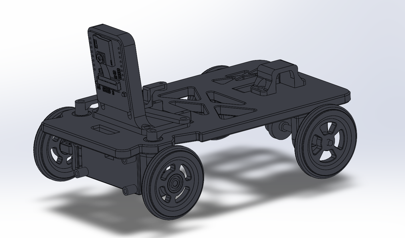
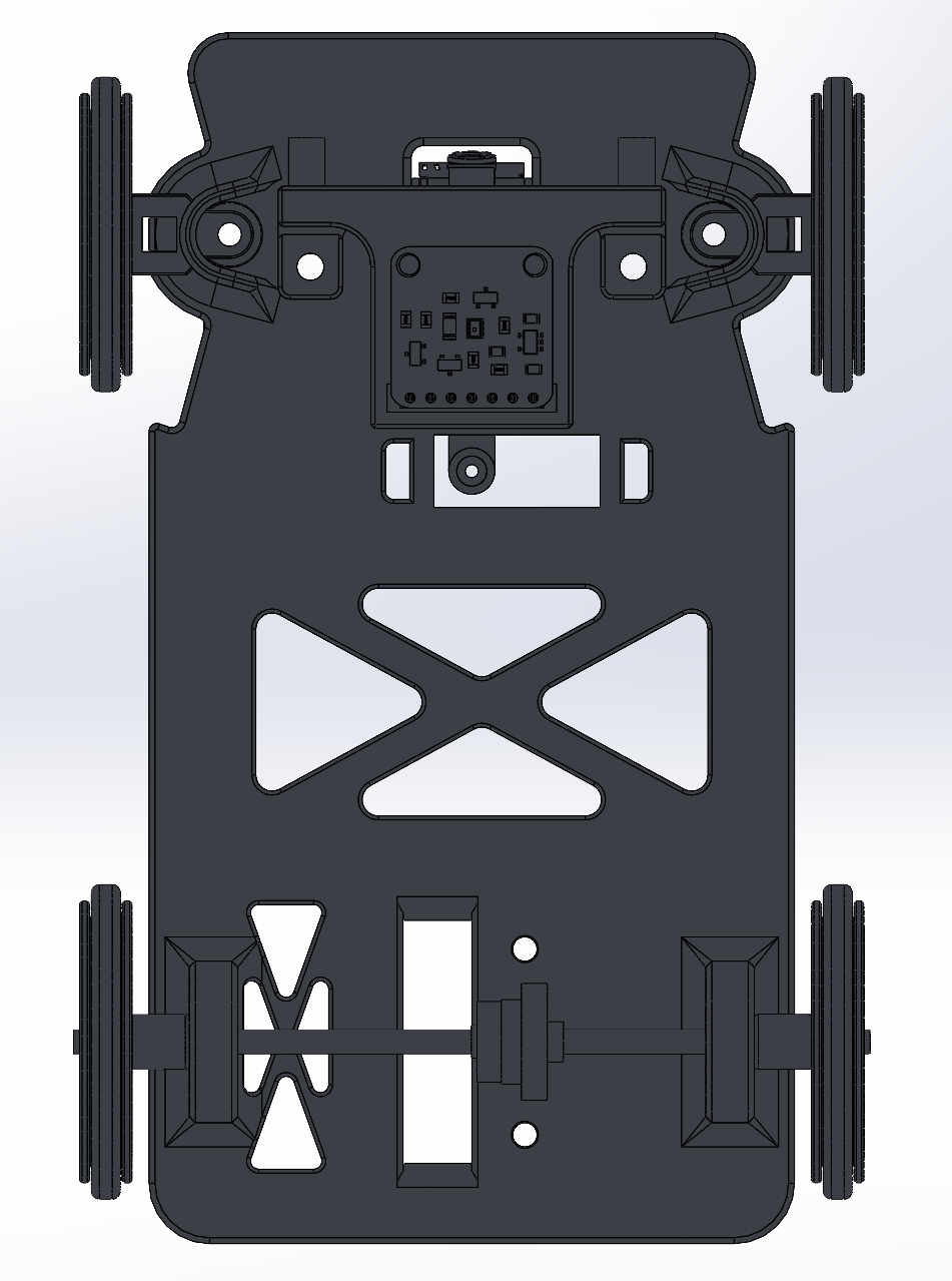
Left: Full assembly isometric view showing overall vehicle form factor • Right: Top-down view revealing chassis layout, electronics bay, steering geometry, and drivetrain routing
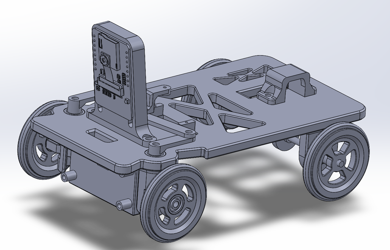
Secondary isometric angle highlighting camera mount, wheel profile, and chassis depth
## ⚙️ Core Mechanical Systems ### 🏗️ Main Chassis
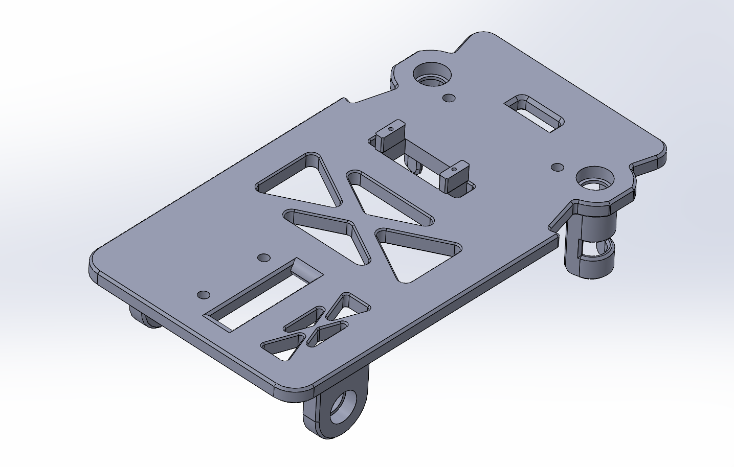
Primary structural plate featuring X-pattern lightening pockets, integrated standoff posts, and dedicated mounting zones for motor, servo, electronics, and sensor assemblies
**Structural Design Elements:** - **Flat-Plate Architecture**: Single-level structural platform keeping CG as low as possible for stability at speed - **X-Pattern Lightening Cutouts**: Triangular pocket geometry maximizes removed mass while preserving structural load paths - **Integrated Standoff Columns**: Raised posts molded into the chassis for direct PCB and cover mounting without separate hardware - **Dedicated Subsystem Zones**: Distinct areas pre-allocated for motor mount, servo, differential, and sensor brackets — no retrofitting required - **Perimeter Mounting Rail**: Continuous edge flange providing multiple attachment points for external brackets and covers --- ### 🔄 Steering System — 4-Part Ackermann Linkage The front steering system uses a 4-component linkage to achieve Ackermann-compliant geometry, ensuring both front wheels track toward a common turn center during cornering to eliminate tire scrub.
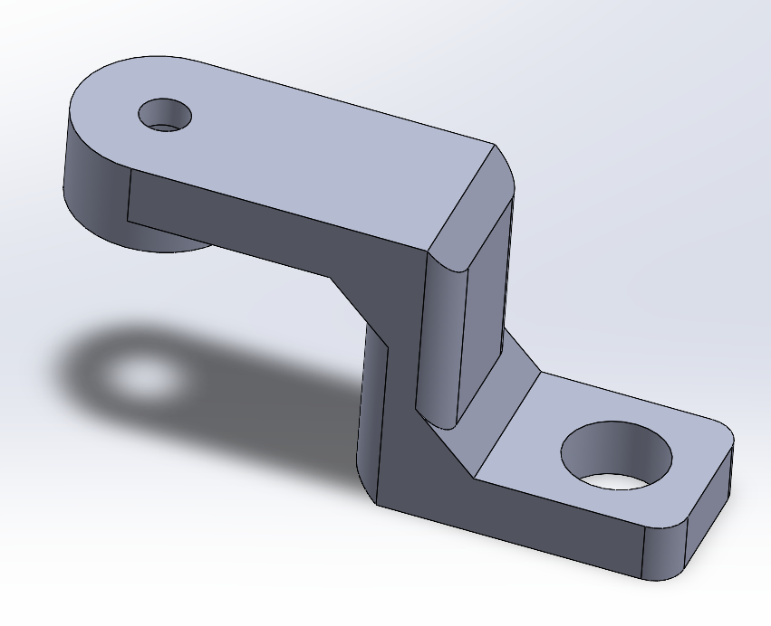 Steer1 — Steering Knuckle |
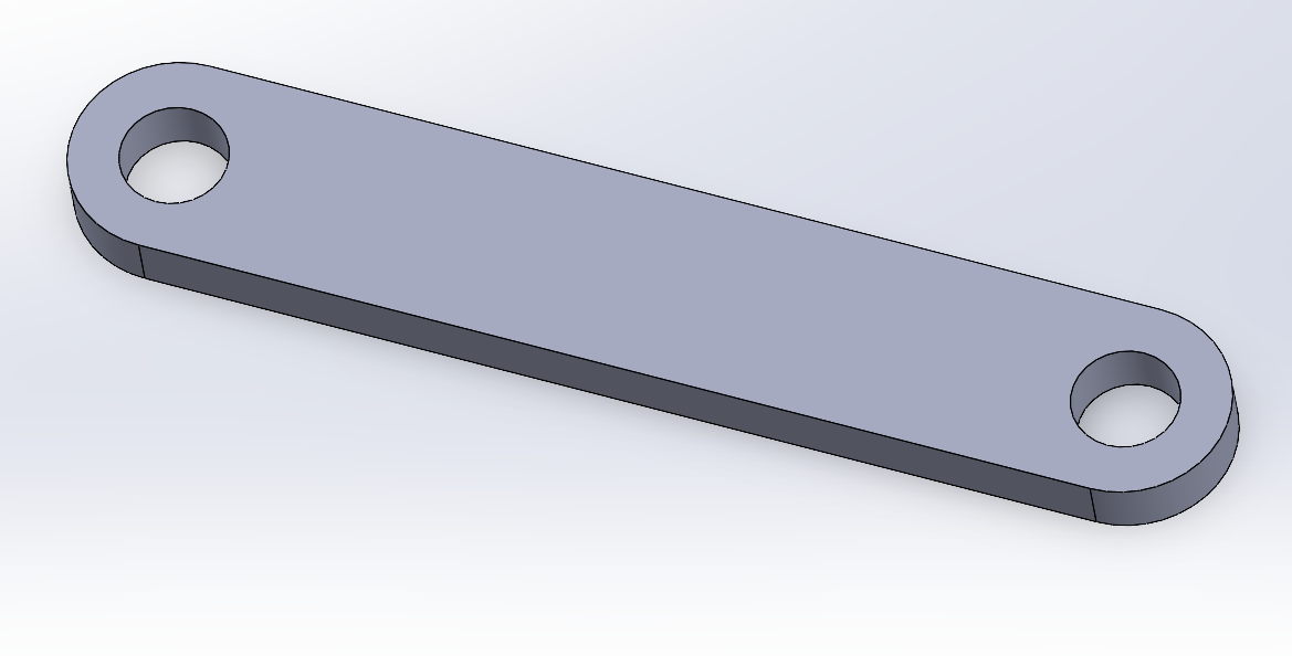 Steer2 — Tie Rod |
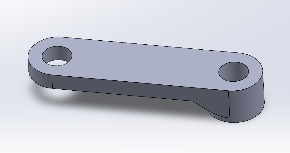 Steer3 — Steering Arm (Left) |
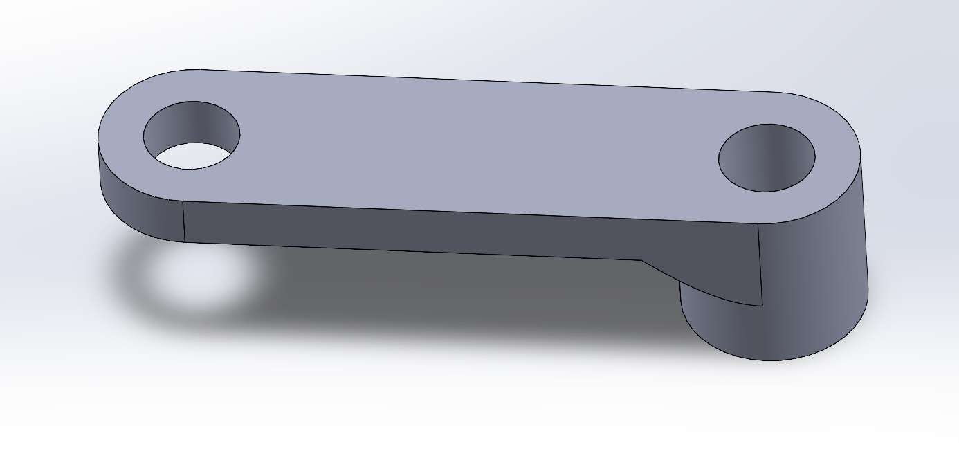 Steer4 — Steering Arm (Right) |
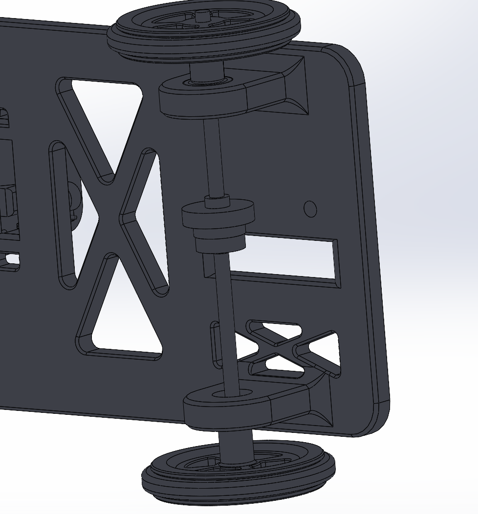
Assembled differential showing rear shaft, gear stack, and bearing assembly — enables independent rear wheel rotation during turns to prevent inside-wheel scrub
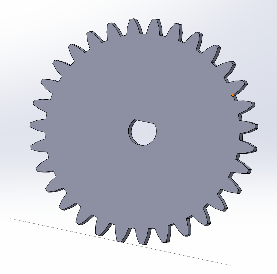 0.8M-31T Motor Gear |
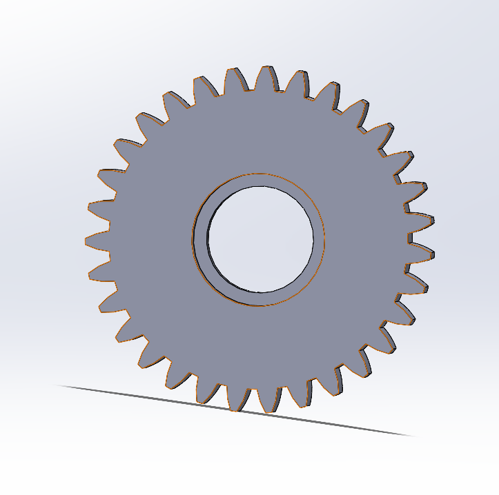 0.8M-31T Driven Gear |
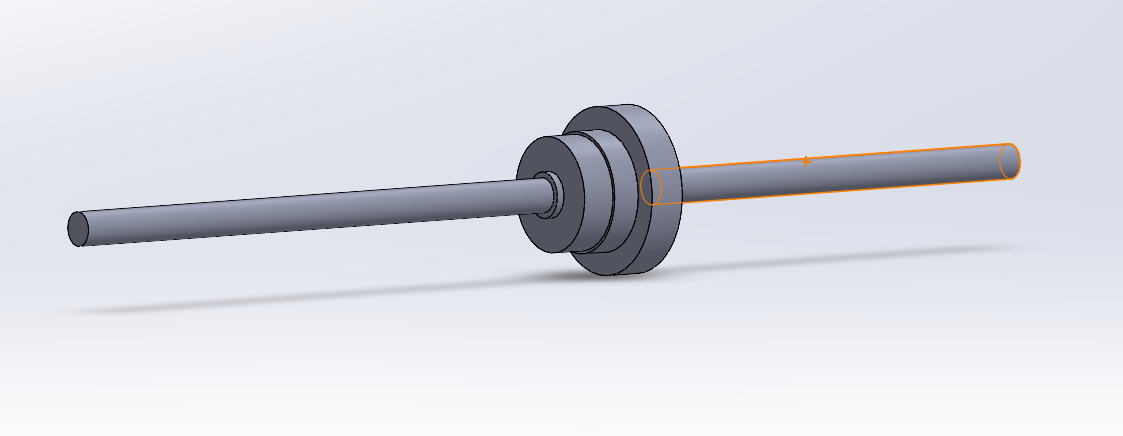 Rear Shaft Assembly |
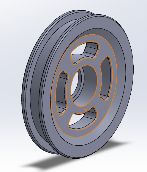 Front Wheel |
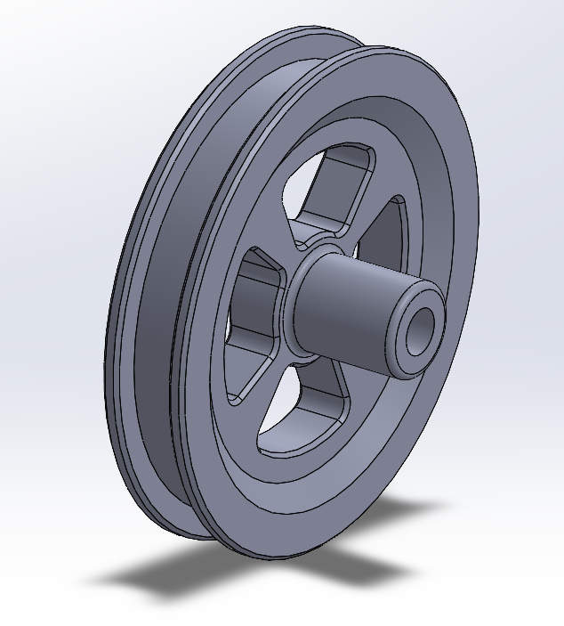 Rear Wheel |
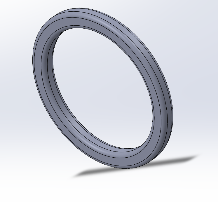 Custom Tire (O-ring) |
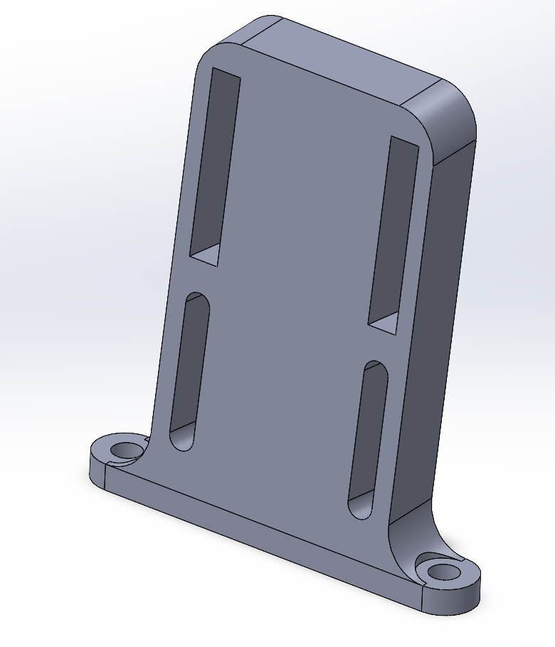 Camera Mount |
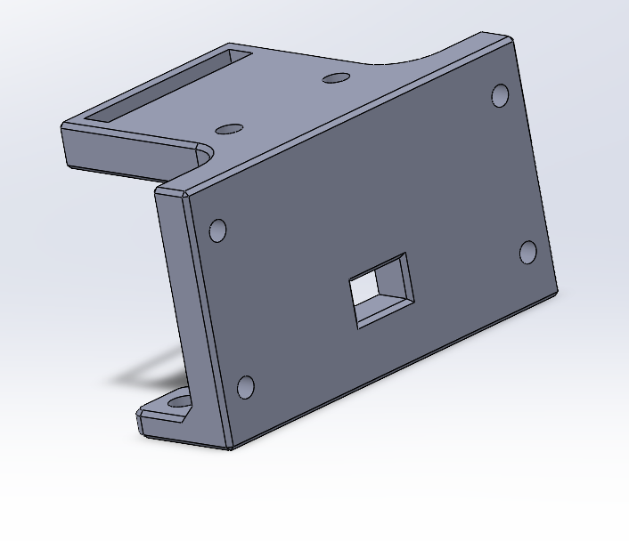 US-100 Ultrasonic Mount |
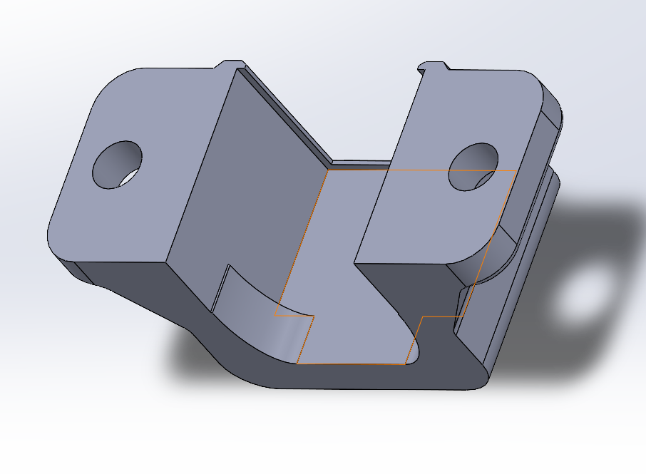
U-bracket motor mount with snap-fit clamp for DC motor body and two M3 bolt holes for chassis attachment
- **U-Bracket Form**: Wraps around the motor body providing support on three sides against vibration and torque reaction - **Snap Clip**: One side features a flexible retention tab that snaps over the motor body for tool-free field replacement - **Dual Mounting Holes**: Two M3 holes on the base flange provide rigid, over-constrained attachment to the chassis to prevent any rocking under drive load - **Gear Alignment**: Mount geometry positions the motor output shaft at the exact center distance required for 0.8M gear mesh with zero adjustment needed --- ### 🛞 Front Wheel Mount
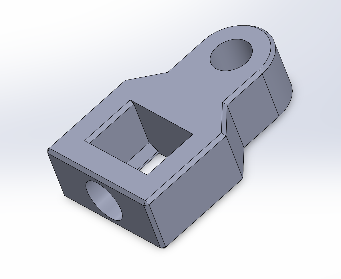
Front wheel upright with square steering pin slot, bearing bore, and dual attachment holes connecting the steering linkage to the wheel spindle
- **Square Slot**: Receives the servo/steering pin ensuring zero rotational slip between steering command and wheel response - **Bearing Bore**: Precision-sized pocket for 3×10×4 bearing press-fit, providing a smooth low-friction pivot axis for the front wheel - **Dual Hole Attachment**: Two mounting points prevent single-point failure and provide the moment arm needed to resist steering loads --- ## 🔩 Hardware Components
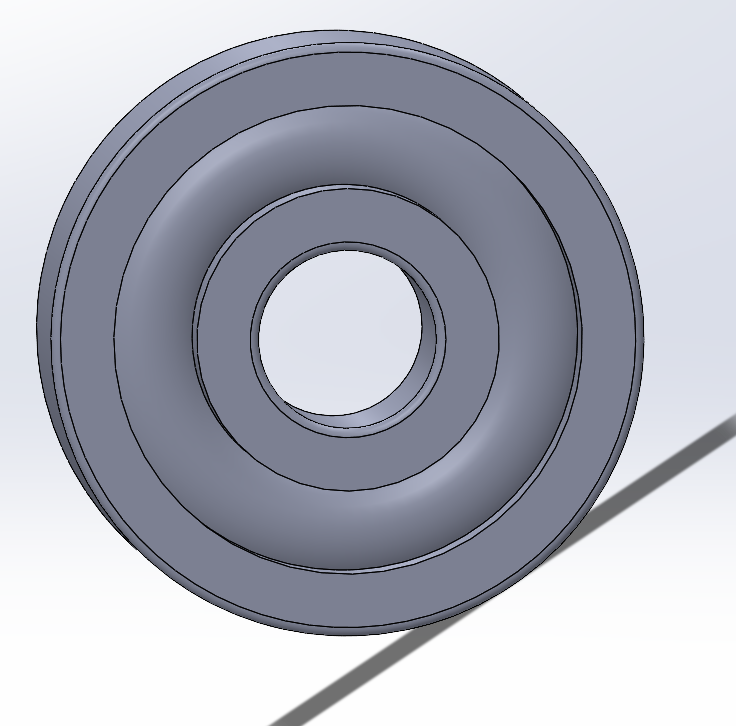 3×10×4 Bearing |
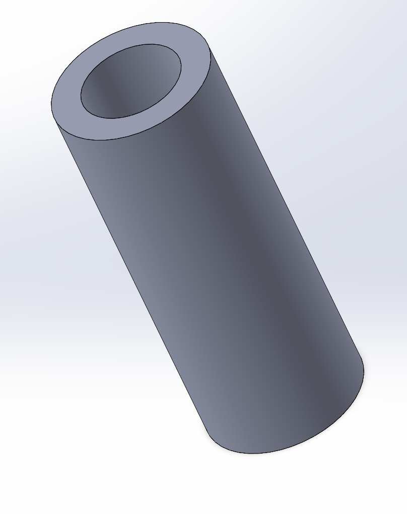 Spacer (Thin) |
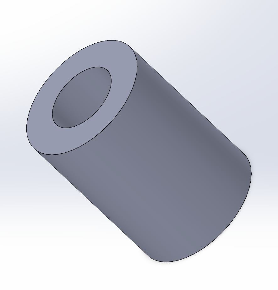 Spacer (Thick) |
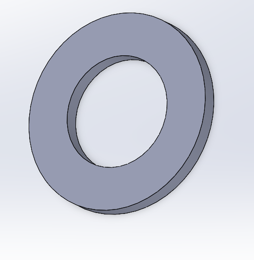 M3 Washer |
| 1 | Primary structural plate with X lightening pockets and integrated mounting zones |
| **Motor Mount** | | 1 | U-bracket with snap clamp for DC motor, two M3 base holes |
| **Front Wheel Mount** | | 2 | Wheel upright with bearing bore and square steering pin slot (left/right) |
| **Steer1 — Steering Knuckle** | | 2 | L-shaped knuckle connecting wheel to chassis pivot (left/right) |
| **Steer2 — Tie Rod** | | 1 | Flat link bar transmitting servo motion to front knuckles |
| **Steer3 — Left Steering Arm** | | 1 | Asymmetric arm with Ackermann offset, left side |
| **Steer4 — Right Steering Arm** | | 1 | Mirror of Steer3 with cylindrical boss for shaft, right side |
| **Front Wheel** | | 2 | 4-spoke rim with recessed 3×10×4 bearing seat |
| **Rear Wheel** | | 2 | 4-spoke rim with direct shaft hub, no bearing |
| **Tire** | | 4 | O-ring torus tire with 3 circumferential grip grooves |
| **0.8M-31T Driven Gear** | | 1 | 31-tooth 0.8M spur gear with large hub bore for rear shaft |
| **0.8M-31T Motor Gear** | | 1 | 31-tooth 0.8M spur gear with small bore for motor output shaft |
| **Rear Shaft** | | 1 | Rear through-axle with differential gear stack and bearing seats |
| **Assembled Differential** | | 1 | Complete differential sub-assembly reference view |
| **Camera Mount** | | 1 | Tall vertical bracket with dual adjustment slots for camera height |
| **US-100 Mount** | | 1 | Box bracket with square sensor cutout and snap-clip retention |
| **Spacer (Thin)** | | TBD | Short hollow spacer for axial component positioning |
| **Spacer (Thick)** | | TBD | Tall hollow spacer for wider axial gaps |
| **3×10×4 Bearing** | | 4+ | Radial ball bearing for front wheel spindles and shaft support |
| **M3 Washer** | | TBD | Standard flat washer for M3 fasteners |
---
## 🏭 Design & Manufacturing
### 🖥️ CAD Platform
All components were modeled in **SolidWorks** with full parametric feature trees, enabling rapid design iteration and precise dimension control. Assembly files validate fit, clearance, and motion range before any part is printed.
### 🖨️ Printer Platform
All parts were printed on a **Bambu Lab A1 Mini** using **Bambu Studio** as the slicer. The A1 Mini's automatic flow calibration, multi-axis vibration compensation, and fast print speeds (up to 500 mm/s travel) made it possible to iterate quickly between design revisions during development. Dimensional accuracy is high out of the box, which is critical for bearing press-fit seats and gear mesh tolerances.
| Setting | Value |
| --- | --- |
| Printer | Bambu Lab A1 Mini |
| Slicer | Bambu Studio |
| Nozzle diameter | 0.4 mm (standard); 0.25 mm for fine gear details if available |
| Bed surface | Textured PEI plate |
| Print speed | 150–250 mm/s for structural parts; 20–25 mm/s for TPU tires |
| Flow calibration | Auto-calibration run before each material change |
### 🖨️ 3D Printing Strategy
- **Target Material**: PLA for initial prototyping; ABS or PETG for competition parts requiring impact resistance and thermal stability
- **Gear Infill**: 100% for all gear components to prevent tooth deformation under repeated meshing load
- **Structural Parts**: 40–60% infill with rectilinear or gyroid pattern for chassis, mounts, and brackets
- **Bearing Seats**: Printed at 0.08–0.1mm layer height for dimensional accuracy required for press-fit bearing installation
- **Orientation**: Parts oriented to place layer lines perpendicular to primary stress direction, maximizing inter-layer tensile strength where needed
### 🧪 Material Selection per Component
#### Material Overview
| Material | Strengths | Weaknesses | Used for |
| --- | --- | --- | --- |
| **PLA** | High dimensional accuracy, stiff, easy to print, gear-friendly surface | Brittle under impact, low heat resistance (~60 °C), not ideal for repeated flex loads | Gears, wheels, low-stress mounts |
| **PETG** | Impact resistant, tough, good layer adhesion, heat resistant (~80 °C), slight flex prevents crack propagation | Slightly lower stiffness than PLA, strings more during printing, bearing seats need careful calibration | Chassis, steering linkage, motor mount, axle |
| **TPU (95A)** | Flexible, elastic, excellent grip and traction, absorbs vibration | Difficult to print fast, cannot be used for rigid structural parts | Tires only |
#### Per-Component Material Decisions
| Component | Material | Infill | Layer Height | Orientation | Reason |
| --- | --- | --- | --- | --- | --- |
| **Main Chassis** | PETG | 50% Gyroid | 0.15 mm | Flat (XY) | Main structural load path; PETG handles corner impacts and motor vibration without brittle fracture |
| **Motor Mount** | PETG | 60% Rectilinear | 0.15 mm | Upright | Holds motor under continuous torque reaction and vibration; PETG's toughness prevents snap at bolt holes |
| **Front Wheel Mount (×2)** | PETG | 55% Gyroid | 0.10 mm | Upright | Bearing press-fit seat demands tight dimensional tolerance; PETG's toughness handles steering side loads |
| **Steer1 — Knuckle (×2)** | PETG | 55% Rectilinear | 0.15 mm | Flat | Repeated bending stress from steering inputs; PETG prevents crack propagation at the L-bend |
| **Steer2 — Tie Rod** | PETG | 50% Rectilinear | 0.15 mm | Horizontal | Under axial tension and compression every steering cycle; PETG is tougher than PLA for slender rod geometry |
| **Steer3 — Left Arm** | PETG | 55% Rectilinear | 0.15 mm | Flat | Asymmetric arm loaded sideways; PETG tolerates the offset bending moment better than PLA |
| **Steer4 — Right Arm** | PETG | 55% Rectilinear | 0.15 mm | Flat | Same reasoning as Steer3 |
| **0.8M-31T Motor Gear** | PLA | 100% Rectilinear | 0.08 mm | Flat (teeth upright) | Gears need stiff, hard tooth surfaces; PLA provides better mesh accuracy and surface hardness than PETG at this scale |
| **0.8M-31T Driven Gear** | PLA | 100% Rectilinear | 0.08 mm | Flat (teeth upright) | Same as motor gear; 100% infill prevents tooth deformation under repeated meshing load |
| **Rear Shaft** | PETG | 80% Rectilinear | 0.12 mm | Horizontal along shaft axis | Primary drivetrain axle under torsion and bending; PETG's toughness handles shock loads at gear mesh point |
| **Front Wheel (×2)** | PLA | 40% Gyroid | 0.15 mm | Flat | Low mechanical stress — only rotates on bearing; PLA gives good dimensional accuracy for bearing seat |
| **Rear Wheel (×2)** | PLA | 40% Gyroid | 0.15 mm | Flat | Fixed to axle, no bearing; low stress; PLA's stiffness is sufficient |
| **Tire (×4)** | TPU 95A | 100% | 0.20 mm | Flat | Must stretch over rim and provide grip; only flexible material suitable for O-ring tire profile |
| **Camera Mount** | PLA | 35% Gyroid | 0.15 mm | Upright | No significant mechanical load; PLA's rigidity keeps camera angle stable; lighter than PETG |
| **US-100 Mount** | PLA | 35% Gyroid | 0.15 mm | Flat | Sensor holder only — no dynamic load; PLA is sufficient and prints cleanly for snap-clip detail |
| **Spacers (Thin / Thick)** | PLA | 100% | 0.10 mm | Upright | Axial positioning parts; need accurate length; 100% infill prevents compression creep |
| **M3 Washer** | PLA | 100% | 0.10 mm | Flat | Load distribution only; if standard metal washers are available, prefer those |
#### Key Printing Notes
- **Bearing seats** (Front Wheel Mount, Front Wheel, Rear Shaft): print at 0.08–0.10 mm layer height and calibrate flow rate before production runs. A 0.1 mm undersized bore is easier to open than reprinting an oversized one.
- **Gears**: orient so tooth layer lines run perpendicular to the tooth face (teeth pointing up/flat print). Use a 0.4 mm nozzle minimum; 0.25 mm nozzle preferred for 0.8M tooth detail.
- **TPU tires**: print slow (20–25 mm/s), disable retraction or use minimal retraction, and set 100% infill for consistent hardness around the circumference.
- **PETG warp**: use a PEI or glass bed at 70–80 °C; avoid cooling fan for first 2–3 layers. Use brim for thin upright parts (Steer arms, Motor Mount).
- **Symmetric parts** (Steer3/Steer4, Front Wheel Mounts): print left and right in the same batch on the same orientation to ensure geometric symmetry.
### 🔄 Design Iteration Process
1. **Conceptual Layout** — Component placement defined in assembly sketch to lock wheelbase, track width, and sensor positions
2. **Individual Part Modeling** — Each component modeled parametrically with design intent captured in feature names and equations
3. **Assembly Validation** — Full assembly checked for interference, range-of-motion clearances, and cable routing paths
4. **Prototype & Test** — First-print fit check, steering geometry validation, and drivetrain engagement verification
5. **Refinement** — Dimensional corrections, wall thickness optimization, and fastener clearance adjustments applied before production prints
## ✅ Mechanical Validation Tests
| Test | Procedure | Acceptance criteria |
| --- | --- | --- |
| Steering range | Move servo from minimum to maximum command while wheels are lifted. | Linkage reaches both steering directions without binding or wheel/chassis contact. |
| Ackermann behavior | Observe inner/outer wheel angles during left and right steering. | Inner wheel turns more sharply than the outer wheel in both directions. |
| Gear mesh | Spin the drivetrain by hand and then under low PWM. | No skipping, tight spots, or visible gear wobble. |
| Differential action | Hold one rear wheel and rotate the opposite wheel gently. | Differential allows relative wheel motion without excessive friction. |
| Bearing fit | Press bearings into front wheel mounts and rotate wheels. | Bearing stays seated and wheel rotates freely. |
| Sensor mount rigidity | Shake chassis lightly and inspect camera/US-100 brackets. | Sensor angle does not shift under normal handling. |
| Track clearance | Roll vehicle through a practice corner and over cable routing. | Chassis, wires, and mounts do not scrape or catch. |
## ⚠️ Mechanical Risks and Mitigations
| Risk | Mitigation |
| --- | --- |
| Servo linkage backlash | Use short linkage parts, tight fasteners, and repeat `servo_tune.py` after assembly. |
| Gear misalignment | Motor mount fixes shaft center distance and assembly is checked before autonomous runs. |
| Camera vibration | Tall camera mount is bolted directly to the chassis and checked before obstacle testing. |
| Printed part warping | Competition parts should be printed with controlled orientation and higher infill where loads are concentrated. |
| Tire slip | O-ring tires provide a simple repeatable contact patch and can be replaced quickly if worn. |
| Battery/electronics weight shift | Chassis has dedicated electronics zones so mass stays low and centered. |
## 🔁 Repeatability Notes
- Keep the same print orientation for left/right steering parts so geometry stays symmetric.
- Ream or lightly clean bearing holes only when needed; oversized seats reduce repeatability.
- Mark final servo horn position after tuning so the steering center can be rebuilt after maintenance.
- Use the same wheel/tire batch during timed tests to avoid traction differences.
- Route sensor cables away from moving steering links and gears before every run.
---
## 🧩 Assembly Guide
### Phase 1: Rear Drivetrain
1. Press 3×10×4 bearings into rear shaft bearing seats
2. Slide driven gear (`0.8M-31T`) onto rear shaft and secure axially with thin spacers
3. Mount motor onto `motorMount` bracket; press motor gear (`08M-31T_Motor`) onto motor output shaft
4. Bolt `motorMount` assembly to chassis — verify gear mesh engagement and backlash
5. Install rear wheels onto shaft ends, securing with washers and locking fasteners
### Phase 2: Front Steering System
1. Press 3×10×4 bearings into `Front_Wheel_Mount` bearing bores
2. Install `Steer1` knuckles into chassis front pivot points
3. Connect `Steer3` and `Steer4` arms to servo output horn and knuckle pins respectively
4. Thread `Steer2` tie rod between knuckle connection points; adjust length for zero toe-in at center
5. Install front wheels onto spindles through bearing bores; verify free rotation with no lateral play
### Phase 3: Sensor & Electronics Integration
1. Bolt `CamMount` to designated chassis standoff holes; slide camera module into slots, set height, tighten
2. Snap US-100 sensor into `US100_Mount` bracket; bolt bracket to front chassis face
3. Install PCB/controller into electronics bay using chassis integrated standoffs
4. Route all wiring through chassis cable channels away from moving drivetrain components
---
## ✅ Validation Checklist
- **Steering Range**: Confirm full left-to-right servo travel translates to expected wheel deflection angles without binding
- **Differential Function**: With rear wheels off ground, verify each rear wheel can rotate independently while the other is held
- **Gear Mesh**: No noise or skip at full motor speed; correct backlash (0.1–0.2mm) between 0.8M gears
- **Bearing Seating**: All bearings fully seated, no axial float, smooth rotation under light finger pressure
- **Sensor Alignment**: Camera FOV centered on track ahead; US-100 sensors aimed level and perpendicular to travel direction
- **Fastener Torque**: All M3 bolts confirmed snug; locking elements (nyloc or threadlocker) applied to high-vibration joints
---
For electrical systems documentation: [Schemes Documentation](../schemes/README.md)
For software implementation and algorithms: [Software Documentation](../src/README.md)
For performance demonstrations: [Video Documentation](../video/README.md)
For additional resources and photos: [Other Documentation](../other/README.md)