# Hardware Setup Guide
## Table of Contents
- [Visual Overview](#visual-overview)
- [Bill of Materials](#bill-of-materials)
- [Required Components](#required-components)
- [Optional Testing Components](#optional-testing-components)
- [Raspberry Pi Setup](#raspberry-pi-setup)
- [Camera Installation](#camera-installation)
- [Live Camera Preview for Positioning](#live-camera-preview-for-positioning)
- [Camera Mounting on Catflap](#camera-mounting-on-catflap)
- [Infrared Setup](#infrared-setup)
- [RFID Jammer Assembly](#rfid-jammer-assembly)
- [Principle](#principle)
- [Wiring Diagram](#wiring-diagram)
- [RFID Module Pinout](#rfid-module-pinout)
- [Assembly Steps](#assembly-steps)
- [Interior Hardware Setup](#interior-hardware-setup)
- [Testing](#testing)
- [Test Relay Control](#test-relay-control)
- [Test RFID Reader Output](#test-rfid-reader-output)
- [Test RFID Blocking](#test-rfid-blocking)
- [RFID Jammer Positioning](#rfid-jammer-positioning)
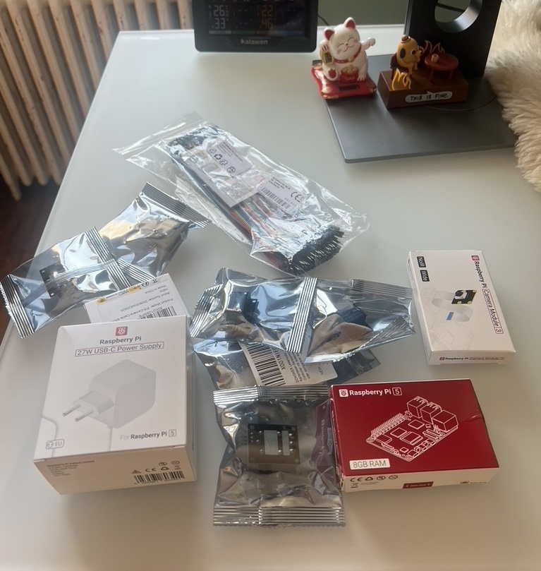
This guide covers the physical assembly and setup of the Catflap Prey Detector system.
## Visual Overview

*All required hardware components for the system*
## Bill of Materials
### Required Components
| Component | Specification | Purchase Link Example|
|-----------|--------------|---------------|
| Raspberry Pi 5 | 4GB or 8GB RAM* | [Amazon FR](https://www.amazon.fr/dp/B0CK2FCG1K) |
| Cooling System | Active cooling fan or heatsink | [Amazon FR](https://www.amazon.fr/dp/B0CZ98DYVM) |
| Power Supply | Official 27W USB-C power supply | [Amazon FR](https://www.amazon.fr/dp/B0CM46P7MC) |
| Picamera 3 IR Wide | Wide angle infrared camera | [Amazon FR](https://www.amazon.fr/dp/B0BRY6VLR6) |
| Camera Cable Extension | Longer camera ribbon cable | [Amazon FR](https://www.amazon.fr/dp/B0D49FTZG5) |
| Infrared Illuminator | 850nm IR LED light | [Amazon FR](https://www.amazon.fr/dp/B07MX63RX3) |
| RFID Reader Module | 134.2 kHz FDX-B reader | [Amazon FR](https://www.amazon.fr/dp/B09SPF26RN) |
| 5V Relay Module | Single-channel relay | [Amazon FR](https://www.amazon.fr/dp/B07BVXT1ZK) |
| Jumper Wires | Male-to-female Dupont wires | [Amazon FR](https://www.amazon.fr/dp/B074P726ZR) |
| MicroSD Card | 32GB+ Class 10 | Any brand |
**Note:** *The system only requires ~1GB RAM, so lower-spec Pi models may work. CPU performance affects YOLO FPS but shouldn't be an issue. I chose the maximum specs to avoid bottlenecks during prototyping.
### Optional Testing Components
| Component | Purpose |
|-----------|---------|
| Extra RFID Microchip | For testing RFID jamming (unless your cat is very cooperative!) |
| Oscilloscope | For testing RFID reader output signal |
## Raspberry Pi Setup
Follow the official Raspberry Pi documentation for initial setup:
[Raspberry Pi Getting Started Guide](https://www.raspberrypi.com/documentation/computers/getting-started.html#setting-up-your-raspberry-pi)
See [Deployment Tools](DEPLOYMENT_TOOLS.md) for advanced remote access options.
## Camera Installation
For detailed camera installation and setup instructions, refer to the official documentation:
[Picamera2 Manual](https://datasheets.raspberrypi.com/camera/picamera2-manual.pdf)
### Live Camera Preview for Positioning
To help position and align your camera correctly, you can use the built-in live stream server:
```bash
uv run python -m catflap_prey_detector.detection.fastapi_mjpeg_server
```
This starts a web server at `http://:8000` that displays a real-time MJPEG stream from the camera. Access it from any device on your network using a web browser.
**Use this tool to:**
- Verify the camera field of view covers the catflap entrance
- Adjust camera angle and mounting position
- Ensure proper framing before final installation
- Test infrared illumination at night
- Check focus and image quality
The stream displays at 640x360 resolution with a timestamp overlay for easy monitoring.
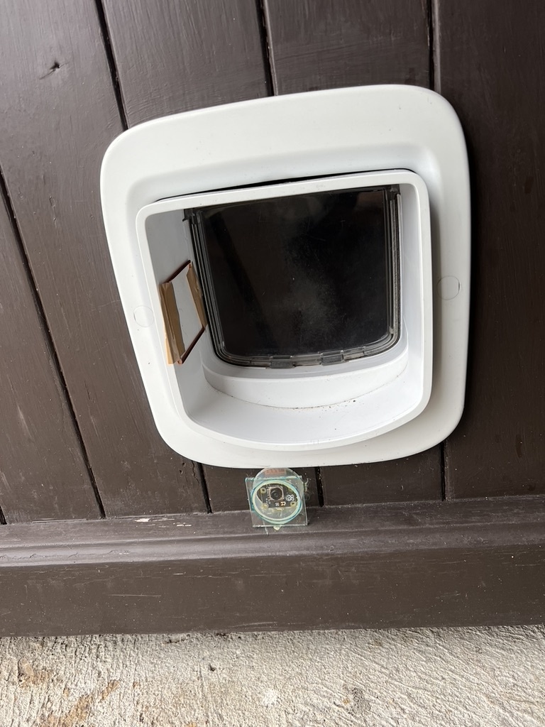
### Camera Mounting on Catflap
Camera with handmade protection mounted on catflap, antenna in tunnel
|
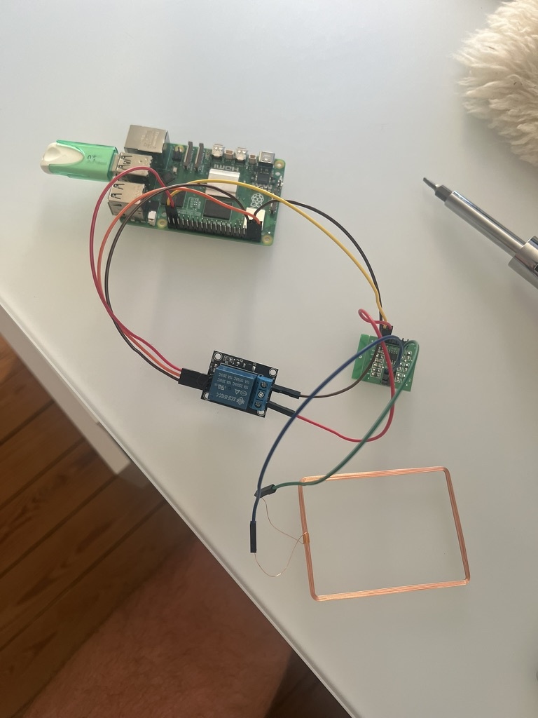
Close-up of RFID jammer assembly without camera
|
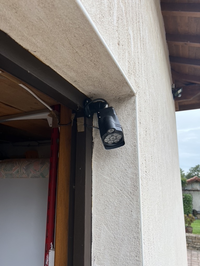
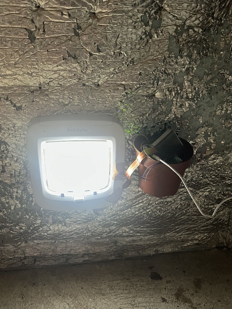
### Infrared Setup

*Infrared illuminator placement for night vision*
## RFID Jammer Assembly
The RFID jammer uses a relay to control a 134.2 kHz RFID reader module, which generates an interfering signal that blocks the catflap's RFID reader.
### Principle
When powered, the RFID reader module emits a 134.2 kHz carrier wave. Positioning this module's antenna next to the catflap's reader creates interference, preventing the catflap from detecting your cat's microchip and entering.
### Wiring Diagram
#### Complete System Wiring
```
┌───────────────────────────────────────────────────────────────────────┐
│ Raspberry Pi 5 │
│ │
│ [5V] ──────┬ │
│ │ │
│ [GND] ──────┼────────────────────┐ │
│ │ │ │
│ Pin 37 [GPIO 26] ──┼────────┐ │ │
│ │ │ │ │
│ [Camera Port] ─────┼────────┼───────────┼────────────────────────┐ │
│ │ │ │ │ │
└─────────────────────┼────────┼───────────┼────────────────────────┼───┘
│ │ │ │
│ │ │ │
│ ┌───▼────┐ │ │
│ │ IN │ │ │
│ ├────────┤ │ │
├───►│ VCC │ │ │
│ ├────────┤ │ │
│ │ GND │◄─────┤ │
│ └───┬────┘ │ │
│ │ │ │
│ ┌───┴────┐ │ │
│ │ COM │◄─────┘ │
│ ├────────┤ │
│ │ NO │──────┐ │
│ ├────────┤ │ │
│ │ NC │ │ │
│ └────────┘ │ │
│ 5V Relay Module │ │
│ │ │
│ ┌───▼────┐ │
│ │ VCC │ │
│ ├────────┤ │
└───────────────►│ GND │ │
├────────┤ │
│ TXD │ (NC) │
├────────┤ │
│ L1 │────┐ │
├────────┤ │ │
│ L2 │──┐ │ │
└────────┘ │ │ │
RFID Reader │ │ │
Module │ │ │
│ │ │
┌────▼─▼───┐ │
│ Antenna │ │
│ Coil │ │
└──────────┘ │
│
│
┌───────────────────────────▼──┐
│ Picamera 3 IR Wide │
└──────────────────────────────┘
```
#### Pin Reference Table
**Relay to Raspberry Pi:**
| Relay Pin | Raspberry Pi Pin | Pin Number |
|-----------|------------------|------------|
| VCC | 5V | Pin 2 or 4 |
| GND | Ground | Pin 6, 9, 14, 20, 25, 30, 34, or 39 |
| IN | GPIO 26 | Pin 37 |
**RFID Module Connections:**
| Connection | Description |
|------------|-------------|
| Pi 5V → Relay COM | Power source to relay common terminal |
| Relay NO → RFID VCC | Normally Open to RFID module power |
| Pi GND → RFID GND | Ground connection |
| RFID L1, L2 | Connect to antenna coil |
**Camera Connection:**
| Component | Connection |
|-----------|------------|
| Picamera 3 IR Wide | Camera ribbon cable to Pi Camera Port |
**Note:** Most 5V relay modules are active-low (relay activates when GPIO is LOW). The code handles this with `active_high=False` configuration.
### RFID Module Pinout
Standard 134.2 kHz FDX-B RFID reader modules typically have:
1. **GND** - Ground
2. **VCC** - 5V power
3. **NC** - Not connected
4. **TXD** - Data output (not used in this project aside from optional testing)
5. **NC** - Not connected
6. **NC** - Not connected
7. **L1** - Antenna connection 1
8. **L2** - Antenna connection 2
### Assembly Steps
1. **Connect Relay to Pi:**
- Relay VCC → Pi 5V
- Relay GND → Pi Ground
- Relay IN → Pi GPIO 26
2. **Wire RFID Module:**
- Pi 5V → Relay COM terminal
- Relay NO terminal → RFID module VCC
- Pi GND → RFID module GND
- Attach antenna to RFID module L1 and L2 pins
- **Note:** The antenna coil likely needs to be soldered to L1 and L2 pins. You can use one or more cables inbetween to facilitate mounting it to the catflap tunnel.
3. **Secure Components:**
- Mount relay and RFID module near the Pi
- Use cable ties or mounting tape
- Ensure antenna coil is free to position near catflap
### Interior Hardware Setup

*Raspberry Pi and cable connections on the interior side*
## Testing
### Test Relay Control
```python
# Test script
import RPi.GPIO as GPIO
import time
GPIO.setmode(GPIO.BCM)
GPIO.setup(26, GPIO.OUT)
# Activate relay (should hear click)
GPIO.output(26, GPIO.LOW) # Active-low relay
time.sleep(2)
# Deactivate relay
GPIO.output(26, GPIO.HIGH)
GPIO.cleanup()
```
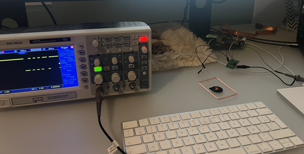
### Test RFID Reader Output
You can verify the RFID reader is working with an oscilloscope connected to the output pin.

*Testing RFID reader output signal with oscilloscope*
### Test RFID Blocking
1. Position the RFID module's antenna directly next to the catflap's reader
2. Run the test script to activate the relay
3. Try scanning a microchip (or your cat's collar) - it should NOT be detected
4. Deactivate the relay - scanning should work again
**Success:** The catflap cannot read the microchip when the jammer is active.
### RFID Jammer Positioning
- Position antenna coil as close as possible to catflap's RFID reader, usually located in the tunnel section of the catflap
Your hardware setup is complete! See [Configuration Guide](CONFIGURATION.md) to configure the software.