Bipolar Nema 11 Stepper motor controlled by L298N Motor controller module.
---------------------------------------

Hardware
------------------------------------
[DataSheet Motor](https://www.pololu.com/product/1205/specs)
[DataSheet L298](http://www.st.com/resource/en/datasheet/l298.pdf)
The L298N H-bridge
Dual Motor Controller Module 2A allows you to control the speed and direction of two DC motors,
or control one bipolar stepper motor with ease.
The L298N H-bridge module can be used with motors
that have a voltage of between 5 and 35V DC.
There is also an onboard 5V regulator,
so if your supply voltage is up to 12V you can also source 5V from the board.
These L298 H-bridge dual motor controller modules
are inexpensive and widely available.
Module pinouts
Consider the following image - match the numbers against the list below the image:

1. DC motor 1 "+" or stepper motor C
2. DC motor 1 "-" or stepper motor D
3. 12V jumper - remove this if using a supply voltage greater than 12V DC. This enables power to the onboard 5V regulator
4. Connect your motor supply voltage here, maximum of 35V DC. Remove 12V jumper if >12V DC
5. GND
6. 5V output if 12V jumper in place,
7. DC motor 1 enable jumper. Leave in for stepper motor. Connect to PWM output for DC motor speed control.
8. IN1 connect to GPIO on Pi
9. IN2 connect to GPIO on Pi
10. IN3 connect to GPIO on Pi
11. IN4 connect to GPIO on Pi
12. DC motor 2 enable jumper. Leave in for stepper motor. Connect to PWM output for DC motor speed control.
13. DC motor 2 "+" or stepper motor A
14. DC motor 2 "-" or stepper motor B
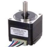
Now the stepper motor , This library was tested
with a typical bipolar NEMA-11 stepper motor with four wires:
It has 200 steps per revolution, and can operate at at 60 RPM.
It was a step to angle ratio of 1.8 degrees per step.
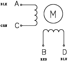
The key to successful stepper motor control is identifying the wires -
that is which one is which. You will need to determine
the A, B, C and D wires.
With our example motor these are green, blue, black and red.
* black wire A == out3 L298N.
* green wire C == out1 L298N.
* red wire B == out4 L298N.
* blue wire D == out2 L298N.
Make these connections.
Place the jumpers included with the L298N module over the pairs at module points 7 and 12.
Then connect the power supply as required to points 4 (positive) and 5 (negative/GND).
Once again if your stepper motor's power supply is less than 12V,
fit the jumper to the module at point 3 which gives you a 5V power supply,
If you wish.
Next, connect L298N module pins IN1, IN2, IN3 and IN4 ,
to any four Raspberry pi GPIO .
I use (GpioPins = [19, 13, 21, 20]) in example and test code.
IN1=19 , IN2 = 13 , IN3 = 21 IN4 = 20.
Finally, connect Pi GND to point 5 on the module.
The software class that controls the motor is same used for the
28BYJ-48 ULN2003 component also in library.
There are 3 step modes available.
Full step and half step there is also wave drive method.
Where one coil at a time is powered (like a wave)
All three methods are available in this library.
Full gives the most torque. Half gives less torque but more accuracy
and wave drive is best for low power applications. half step mode is recommend
for most projects.
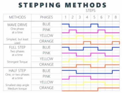
half-step takes twice as many steps to complete same distance.
Half-step mode:
360 degrees / 400 steps = 0.9.
8 step control signal sequence.
0.9 degrees per step , 400 steps , 400/8 = 50 step sequence for one revolution.
7.2 degrees per step sequence.
Full Step mode and wave drive: 4
360 degrees/200 steps = 1.8
4 step control signal sequence.
1.8 degrees per step , 200 steps = 200/4 = 50 step sequence for one revolution.
7.2 degrees per step sequence.
Software
--------------------------------------------
Same software as 28BYJ-48 but with
minor change in class definition for verbose output.
The library file RpiMotorLib.py has a class which controls the motor with one
main function. The example file in the example folder is called L298_Step_Test.py.
When initializing the class pass a name and motor type.
NB **Set motor type to Nema for this component**
The class is called BYJMotor.
`BYJMotor(name, motor_type)`
| ID | Name | Type | Help |
|-----|---------|----------|----------|
| (1) | name | type=string, default="BYJMotorX" | motor_id |
| (2) | motor_type | type=string, default="28BYJ" | calculate degree in verbose output 2 options , Nema and 28BYJ. Nema for this component |
The first method is called motor_run- moves stepper motor based on 7 inputs.
`motor_run(GPIOPins, wait, steps, counterclockwise, verbose, steptype, initdelay)`
| ID | Name | Type | Help |
|-----|------|-------|------|
| (1) | GpioPins, | List of ints 4 long, | 4 GPIO pins to connect to motor controller, GPIOPins[0] is plugged into Pin IN1 on the stepper motor. |
| (2) | wait, | float, default=0.001, | Time to wait(in seconds) between steps. |
| (3) | steps, | int, default=512, | Number of step control signal sequence to take. |
| (4) | ccwise (counterclockwise), | bool default=False | Turn stepper counterclockwise |
| (5) | verbose, | bool default=False | Write pin actions and provide verbose output |
| (6) | steptype, | string , default="half" | Type of drive to step motor 3 options
"full" = fullstep
"half" = half step
"wave" = wave drive. |
| (7) | initdelay, | float, default=1mS, | Initial delay after GPIO pins initialized but before motor is moved, gives time for GPIO to initialize. |
The second method is called to stop the motor when the motor is moving.
motor_stop(), if you wish to stop motor before end of its run. You can also stop with keyboard interrupt.
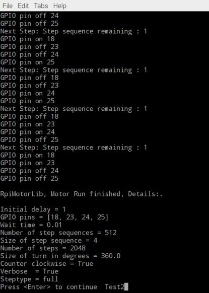
If verbose is set to True various information on pin output and status is outputted to screen at end of a run