[Deutsch](modbus-de.md) • English
# Modbus
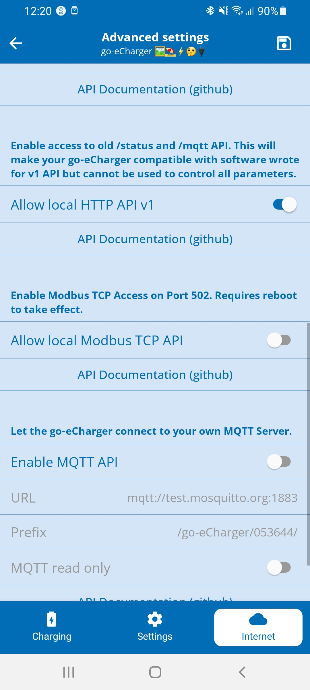
The go-eCharger has a Modbus TCP Interface an which can be used to read some power and energy values. This interface has to be enabled from the app or the [http API](http-en.md). Data can be read with the [Modbus function 3](https://www.simplymodbus.ca/FC03.htm) and the [Modbus function 4](https://www.simplymodbus.ca/FC04.htm). Data can be written with the [Modbus function 16](https://www.simplymodbus.ca/FC16.htm). After enabling the tcp port 502 is used.
| Function No | Name | Supported? |
| ----------- | ------------------------- | ----------------------------------- |
| 01 | Read Coil Status | No |
| 02 | Read Input Status | No |
| 03 | Read Holding Registers | Yes, for all registers listed below |
| 04 | Read Input Registers | Yes, for all registers listed below |
| 05 | Force Single Coil | No |
| 06 | Preset Single Register | No |
| 15 | Force Multiple Coils | No |
| 16 | Preset Multiple Registers | Yes, for all registers listed below |
## Using the App to enable and verify the Modbus interface
Tap the tab "Internet" at the bottom, then click on "Advanced Settings" in the menu, then at the very bottom "Modbus"
 ## Writing Modbus Registers
To write a Modbus Register you need to use FN16!
FN6 ist not implementet! So if you need to write a single Register you still need to use FN16!
## Using the http API to enable and verify the Modbus interface
The chargers provide api keys to configure and verify the modbus interface. These api keys can be used with the http api.
Example: http://192.168.0.77/api/set?men=true
| api key | description | datatype | R?W? | Category |
| ------- | ---------------------------- | -------- | ---- | -------- |
| men | modbus slave enabled | bool | R/W | Config |
| msp | modbus slave port (requires reboot) | uint16 | R/W | Config |
| msb | modbus slave swap bytes | bool | R/W | Config |
| msr | modbus slave swap registers | bool | R/W | Config |
| mro | modbus slave read operations | size_t | R | Status |
| mwo | modbus slave write operations | size_t | R | Status |
## Modbus Profile
### Holding Registers (read/write)
The byte order in firmware version 60.3 was swapped. This was fixed in version 60.4.
Data in this table can be read with modbus function 03 and written with modbus function 16.
| Register (wire-format) | Name | Register Type | Data type | Lenght | Description |
| ---------------------- | --------------------------- | -----------------| --------- | ------ | - |
| 40201 (200) | ALLOW | Holding Register | uint16_t | 1 | **allow_charging:** PWM Signal is allowed
to abut
0: no
1: yes |
| 40202 (201) | ACCESS_STATE | Holding Register | uint16_t | 1 | **access_state**: access control.
0: open
1: RFID / App needed
2: electricity price / automatic
3: scheduler |
| 40205 (204) | CABLE_LOCK_MODE | Holding Register | uint16_t | 1 | Cable lock setting
0: Lock while the car is connected
1: Unlock automatically after
charging
2: Always keep the cable locked |
| 40207 (206) | LED_BRIGHTNESS | Holding Register | uint16_t | 1 | **LED brightness** from 0-255
0: LED off
255: LED brightness max |
| 40208 (207) | LED_SAVE_ENERGY | Holding Register | uint16_t | 1 | **led_save_energy**: LED switch off
automatically after 10 seconds
0: Energy saving function deactivated
1: Energy saving function activated |
| 40209 (208) | ELECTRICITY_PRICES_HOURS | Holding Register | uint16_t | 1 | Minimum **count** of hours that must be
charged with "Electricity price - automatic"
Example: 2 ("Car is full enough after 2 hours") |
| 40210 (209) | ELECTRICITY_PRICES_FINISHED | Holding Register | uint16_t | 1 | Hour (**time**) in which with "electricity price
- automatic" the charge must have lasted
at least aho hours.
Example: 7 ("Ready by 7:00, so charged at
least 2 hours before that") |
| 40211 (210) | ELECTRICITY_PRICES_ZONE | Holding Register | uint16_t | 1 | Awattar price zone
0: Austria
1: Germany |
| 40212 (211) | AMPERE_MAX | Holding Register | uint16_t | 1 | Absolute Max Amps: Maximum
value for Amps setting
Example: 20 (setting to more than
20A in the app not possible) |
| 40213 (212) | AMPERE_L1 | Holding Register | uint16_t | 1 | Ampere level 1 for push button on the
device.
6-32: Ampere level activated
0: Level deactivated (will be skipped) |
| 40214 (213) | AMPERE_L2 | Holding Register | uint16_t | 1 | Ampere level 2 for push button on the
device.
6-32: Ampere level activated
0: Level deactivated (will be skipped) |
| 40215 (214) | AMPERE_L3 | Holding Register | uint16_t | 1 | Ampere level 3 for push button on the
device.
6-32: Ampere level activated
0: Level deactivated (will be skipped) |
| 40216 (215) | AMPERE_L4 | Holding Register | uint16_t | 1 | Ampere level 4 for push button on the
device.
6-32: Ampere level activated
0: Level deactivated (will be skipped) |
| 40217 (216) | AMPERE_L5 | Holding Register | uint16_t | 1 | Ampere level 5 for push button on the
device.
6-32: Ampere level activated
0: Level deactivated (will be skipped) |
| 40218 (217) | CLOUD_DISABLED | Holding Register | uint16_t | 1 | **Cloud disabled**
0: cloud enabled
1: cloud disabled |
| 40219 (218) | NORWAY_MODE | Holding Register | uint16_t | 1 | **Norway mode** activated
0: deactivated (ground detection
activated)
1: activated (no ground detection,
only intended for IT networks) |
| 40300 (299) | AMPERE_VOLATILE | Holding Register | uint16_t | 1 | Amps Value for the PWM
signaling in whole amps of
**6-32A**
Is not saved in the EEPROM
and is **reset** to the value last saved in the EEPROM during the next boot process.
For energy control |
| 40301 (300) | AMPERE_EEPROM | Holding Register | uint16_t | 1 | Amps Value for the PWM
signaling in whole amps of
**6-32A**
Is saved in the EEPROM (max.
write cycles approx. 100, 000) |
| 40333 (332) | PHASE_SWITCH_MODE | Holding Register | uint16_t | 1 | Same as api key psm, only accepts values 0, 1, 2 (Since Firmware 55.5) |
| 40334 (333)
30335 (334)
30336 (335)
30337 (336) | ENERGY_LIMIT | Holding Register | float64 | 4 | Same as api key dwo, set to float Inf to express "null" limit (disabled limit), or any other float in watthours (Wh) (Since Firmware 55.5) |
| 40338 (337) | FORCE_STATE | Holding Register | uint16_t | 1 | Same as api key frc, only accepts values 0, 1, 2 (Since Firmware 55.6) |
### Input Registers (read-only)
Data in this table can be read with modbus function 04.
| Register(wire-format) | Name | Register Type | Data type | Lenght | Description |
| -------------------------- | --------------- | -------------- | -------------- | ------ | - |
| 30101 (100) | CAR_STATE | Input Register | uint16_t | 1 | **Status PWM signaling**
0: Unknown, Charging station defective
1: Charging station ready, no car
2: Car is charging
3: Waiting for car
4: Charging finnished, Car still connected |
| 30102 (101) | PP_CABLE | Input Register | uint16_t | 1 | Type2 **Cable ampere coding**
13-32: ampere coding
0: no cable |
| 30106 (105)
30107 (106) | FWV | Input Register | ascii (4 byte) | 2 | Firmware version as ASCII |
| 30108 (107) | ERROR | Input Register | uint16_t | 1 | error:
1: RCCB (Residual current circuit breaker)
3: PHASE (phase disturbance)
8: NO_GROUND (Ground detection)
10, default: INTERNAL (Others) |
| 30109 (108)
30110 (109) | VOLT_L1 | Input Register | uint32_t | 2 | Voltage on L1 in volts |
| 30111 (110)
30112 (111) | VOLT_L2 | Input Register | uint32_t | 2 | Voltage on L2 in volts |
| 30113 (112)
30114 (113) | VOLT_L3 | Input Register | uint32_t | 2 | Voltage on L3 in volts |
| 30115 (114)
30116 (115) | AMP_L1 | Input Register | uint32_t | 2 | Amps on L1 in 0.1A (123 equals 12, 3A) |
| 30117 (116)
30118 (117) | AMP_L2 | Input Register | uint32_t | 2 | Amps on L2 in 0.1A (123 equals 12, 3A) |
| 30119 (118)
30120 (119) | AMP_L3 | Input Register | uint32_t | 2 | Amps on L3 in 0.1A (123 equals 12, 3A) |
| 30121 (120)
30122 (121) | POWER_TOTAL | Input Register | uint32_t | 2 | Total power in 0.01W (360000 corresponds to 3.6kW) |
| 30129 (128)
30130 (129) | ENERGY_TOTAL | Input Register | uint32_t | 2 | Total amount of energy charged in 0.1kWh (360 corresponds to 36kWh) |
| 132
133 | ENERGY_CHARGE | Input Register | uint32_t | 2 | **Amount of energy charged** in
Deka-Watt-Seconds
Example: 100, 000 means 1, 000, 000
Ws (= 277Wh = 0.277kWh) were loaded in this charging process. |
| 144
145 | VOLT_N | Input Register | uint32_t | 2 | Voltage on N in volts |
| 146
147 | POWER_L1 | Input Register | uint32_t | 2 | Power on L1 in 0.1kW (36 corresponds to 3.6kW) |
| 148
149 | POWER_L2 | Input Register | uint32_t | 2 | Power on L2 in 0.1kW (36 corresponds to 3.6kW) |
| 150
151 | POWER_L3 | Input Register | uint32_t | 2 | Power on L3 in 0.1kW (36 corresponds to 3.6kW) |
| 152
153 | POWER_FACTOR_L1 | Input Register | uint32_t | 2 | Power factor on L1 in % |
| 154
155 | POWER_FACTOR_L2 | Input Register | uint32_t | 2 | Power factor on L2 in % |
| 156
157 | POWER_FACTOR_L3 | Input Register | uint32_t | 2 | Power factor on L3 in % |
| 158
159 | POWER_FACTOR_N | Input Register | uint32_t | 2 | Power factor on N in % |
| 200 | ALLOW | Input Register | uint16_t | 1 | **allow_charging:** PWM Signal is allowed
to abut
0: no
1: yes |
| 202 | ADAPTER_INPUT | Input Register | uint16_t | 1 | **adapter_in**: The charging box
is connected with an adapter
0: NO_ADAPTER
1: 16A_ADAPTER |
| 203 | UNLOCKED_BY | Input Register | uint16_t | 1 | Number of the RFID card that
activated the current charging process
|
| 205 | PHASES | Input Register | uint16_t | 1 | **Phases** before and after the contactor
binary flags: 0b00ABCDEF
A... phase 3, before the contactor
B... phase 2 before the contactor
C... phase 1 before the contatctor
D... phase 3 after the contactor
E... phase 2 after the contactor
F... phase 1 after the contactor
pha 0b00001000: Phase 1 is
available
pha 0b00111000: Phase1-3 is
available
|
| 301
302
303 | MAC | Input Register | char[6] | 3 | MAC address of the WLAN station, binary |
| 304
305
306
307
308
309 | SNR | Input Register | ascii (12 byte) | 6 | Serial number of the go-eCharger, as
ASCII |
| 310
311
312
313
314 | HOSTNAME | Input Register | ascii (12 byte) | 6 | Host name of the go-eCharger, as ASCII |
| 315
316
317
318 | IP | Input Register | ascii (8 byte) | 4 | IP address of the go-eCharger, 1 byte per register |
| 319
320
321
322 | SUBNET | Input Register | unsigned integer (64) | 4 | Subnet mask of the go-eCharger, 1
byte per register |
| 30324 (323)
30325 (324)
30326 (325)
30327 (326) | GATEWAY | Input Register | ascii (4 byte) | 4 | Go-eCharger gateway, 1 byte per register |
| 30328 (327)
30329 (328)
30330 (329)
30331 (330)
30332 (331) | RFID_CARD | Input Register | binary (10 byte) | 5 | Last scanned RFID serial number, 4-byte and 7-byte long numbers will be filled with zeros at the end, 10-byte numbers already fill the 5 modbus register on its own (Since Firmware 55.5) |
| 30333 (332)
30334 (333)
30335 (334)
30336 (335) | ENERGY_CARD0 | Input Register | double | 4 | Energy on RFID Card 1 (in W) |
| 30337 (336)
30338 (337)
30339 (338)
30340 (339) | ENERGY_CARD1 | Input Register | double | 4 | Energy on RFID Card 2 (in W) |
| 30341 (340)
30342 (341)
30343 (342)
30344 (343) | ENERGY_CARD2 | Input Register | double | 4 | Energy on RFID Card 3 (in W) |
| 30345 (344)
30346 (345)
30347 (346)
30348 (347) | ENERGY_CARD3 | Input Register | double | 4 | Energy on RFID Card 4 (in W) |
| 30349 (348)
30350 (349)
30351 (350)
30352 (351) | ENERGY_CARD4 | Input Register | double | 4 | Energy on RFID Card 5 (in W) |
| 30353 (352)
30354 (353)
30355 (354)
30356 (355) | ENERGY_CARD5 | Input Register | double | 4 | Energy on RFID Card 6 (in W) |
| 30357 (356)
30358 (357)
30359 (358)
30360 (359) | ENERGY_CARD6 | Input Register | double | 4 | Energy on RFID Card 7 (in W) |
| 30361 (360)
30362 (361)
30363 (362)
30364 (363) | ENERGY_CARD7 | Input Register | double | 4 | Energy on RFID Card 8 (in W) |
| 30365 (364)
30366 (365)
30367 (366)
30368 (367) | ENERGY_CARD8 | Input Register | double | 4 | Energy on RFID Card 9 (in W) |
| 30369 (368)
30370 (369)
30371 (370)
30372 (371) | ENERGY_CARD9 | Input Register | double | 4 | Energy on RFID Card 10 (in W) |