# 🐕 Robotic Dog — 12-DOF Quadruped Robot
A custom-built **12-DOF quadruped robot** designed, CAD-modeled, 3D-printed, assembled, and programmed as an ongoing robotics development platform.
The current prototype uses an **ESP32** for low-level hardware control and subsystem validation. The robot has progressed from mechanical design and electronics bring-up to **initial physical locomotion testing**. Future development will focus on improving gait stability, balance, sensing, and autonomous behavior, with a planned migration to **STM32** for the next-generation low-level controller.
> 🚧 **Project Status:** Active Development
> **Degrees of Freedom:** 12
> **Current Controller:** ESP32
> **Actuators:** 12 Servo Motors
> **Servo Driver:** PCA9685
> **Prototype:** 3D-Printed Quadruped
---
## 🎥 Walking Demonstration
### First Physical Locomotion Test
The following GIF shows the first physical locomotion experiment of the 12-DOF quadruped prototype.
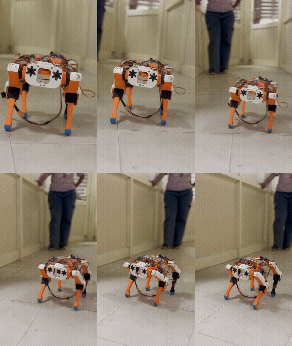
The current gait is experimental. The robot is being progressively developed toward more stable, repeatable, and controlled quadrupedal walking.
> **Current locomotion stage:** Initial walking experiment
---
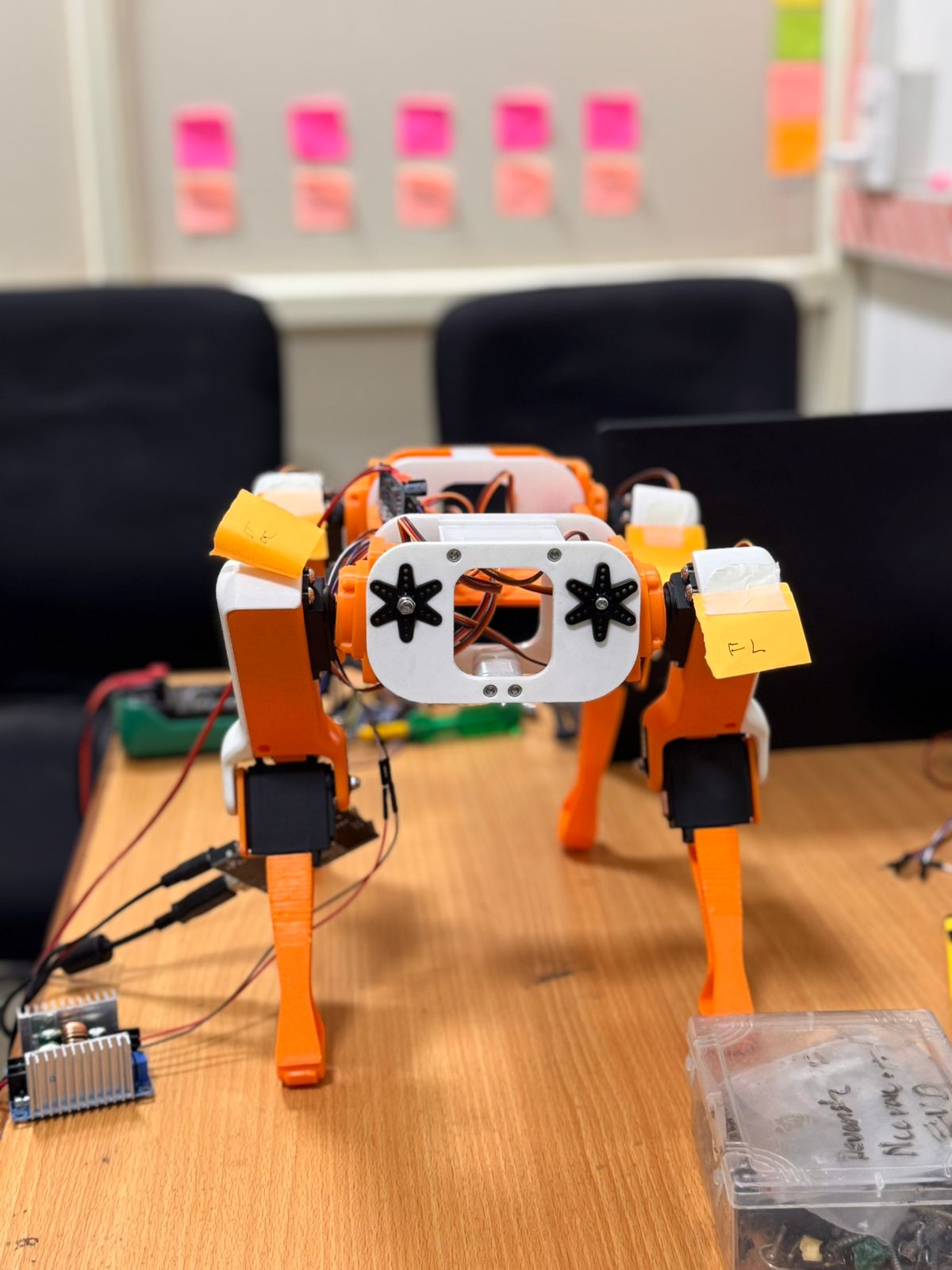
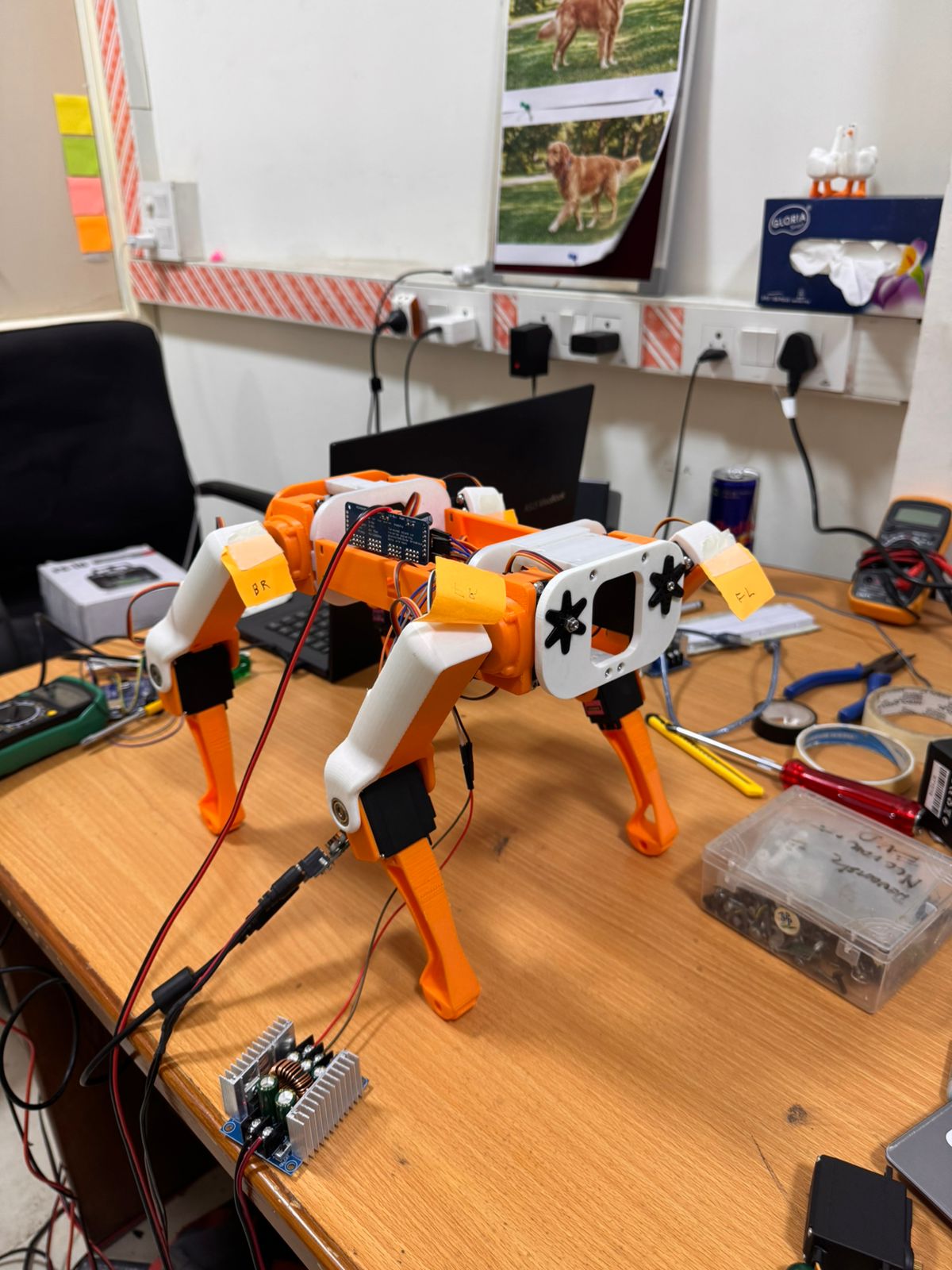
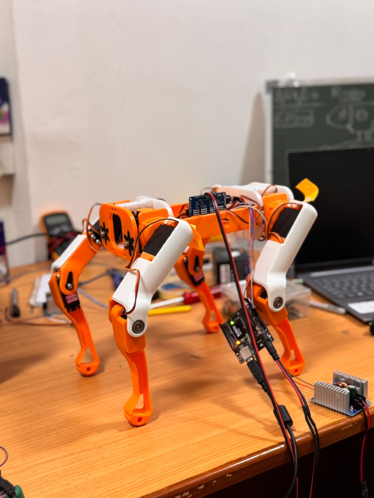
## 📸 Prototype
---
# 🤖 Project Overview
This project focuses on the development of a custom **12-DOF quadruped robot**, covering the development process from mechanical design and 3D printing to embedded electronics, sensor integration, and locomotion.
The robot is designed as a modular experimental platform for studying:
- Quadrupedal locomotion
- Embedded control
- Servo actuation
- Sensor integration
- Balance and stability
- Power monitoring
- Mechanical design
- 3D-printed robotics
- Autonomous navigation
The development follows an incremental hardware-first approach:
```text
Mechanical Design
↓
3D Printed Prototype
↓
Mechanical Assembly
↓
Electronics Integration
↓
Hardware Bring-up
↓
Servo Calibration
↓
Standing Posture
↓
Initial Locomotion
↓
Stable Walking
↓
Balance Control
↓
Sensor Fusion
↓
Autonomous Navigation
```
---
# 🔢 Key Specifications
| Parameter | Current Specification |
|-----------|-----------------------|
| Robot Type | Quadruped |
| Degrees of Freedom | 12 |
| Actuators | 12 Servo Motors |
| Current Controller | ESP32 |
| Planned Controller | STM32 |
| Servo Driver | PCA9685 |
| IMU | MPU6500 |
| ToF Sensors | VL53L0X ×2 |
| Ultrasonic Sensors | HC-SR04 ×2 |
| Foot Contact Sensors | FSR ×4 |
| Current Sensors | ACS758 ×3 |
| Battery | 3S LiPo |
| Manufacturing | 3D Printing |
| Primary CAD | Autodesk Fusion 360 |
> Specifications will be updated as the hardware is experimentally characterized.
---
# ⚙️ System Architecture
The robot is being developed using a modular hardware architecture.
```text
┌─────────────────────┐
│ ESP32 │
│ Low-Level Control │
└──────────┬──────────┘
│
┌─────────────────────┼─────────────────────┐
│ │ │
▼ ▼ ▼
┌────────────┐ ┌────────────┐ ┌─────────────┐
│ PCA9685 │ │ MPU6500 │ │ Sensors │
│ Servo │ │ IMU │ │ & Power │
│ Driver │ └────────────┘ └─────────────┘
└─────┬──────┘
│
▼
┌───────────────┐
│ 12 Servos │
│ 12-DOF Legs │
└───────────────┘
```
The architecture is intended to evolve as higher-level sensing, control, and autonomy are integrated.
---
# 🦿 Mechanical Design & Analysis
The mechanical system is designed as a **12-DOF quadruped platform**, with three actuated joints per leg.
## Leg Configuration
Each leg is designed around three actuated joints:
- Hip
- Knee
- Ankle
```text
BODY
│
┌───┴───┐
│ │
HIP HIP
│ │
KNEE KNEE
│ │
ANKLE ANKLE
│ │
FOOT FOOT
```
The mechanical design emphasizes:
- Modular assembly
- 3D-printable components
- Servo accessibility
- Compact mechanical packaging
- Replaceable components
- Ease of maintenance
- Future design iteration
---
## 📐 CAD Design
The complete mechanical assembly is available in:
```text
CAD/
├── ROBOTIC DOG.step
├── *.stl
└── README.md
```
The STEP assembly provides the complete mechanical model, while the individual STL files provide printable components exported from the CAD design.
The CAD files can be inspected and further modified using software such as:
- Autodesk Fusion 360
- SolidWorks
- FreeCAD
---
## 🖨️ 3D-Printable Parts
Individual STL files are included in the repository so that the mechanical design can be reproduced and modified.
The current CAD folder contains components including:
- Structural plates
- Leg components
- Joint components
- Servo mounting components
- Sensor mounting components
- Covers
- Foot components
The STL files represent the current prototype design and may change as mechanical testing and locomotion development continue.
---
## 🔩 Mechanical Design Considerations
The mechanical design is being evaluated based on:
- Joint loading
- Servo torque requirements
- Robot mass
- Center of mass
- Link geometry
- Structural stiffness
- Servo mounting strength
- 3D-printing tolerances
- Weight distribution
---
# 📊 Mechanical Analysis
Mechanical characterization is an ongoing part of the project.
## Torque Budget
The required joint torque will be calculated using:
- Robot mass
- Link lengths
- Center of mass
- Joint configuration
- Static loading
- Dynamic loading
- Acceleration during locomotion
The final torque budget will be compared against the actual servo specifications.
| Joint | Required Torque | Servo Rated Torque | Safety Margin |
|-------|-----------------|---------------------|---------------|
| Hip | TBD | TBD | TBD |
| Knee | TBD | TBD | TBD |
| Ankle | TBD | TBD | TBD |
> Torque values will be added after the robot geometry, mass distribution, and servo specifications are experimentally verified.
---
## ⚖️ Mass Analysis
The complete robot mass will be experimentally measured.
| Component | Mass |
|-----------|------|
| 3D-Printed Structure | TBD |
| Servo Motors | TBD |
| Electronics | TBD |
| Battery | TBD |
| Wiring & Hardware | TBD |
| **Total Robot Mass** | **TBD** |
The measured mass will later be used for torque calculations and locomotion analysis.
---
## 🧪 FEA Analysis
Finite Element Analysis will be performed on mechanically critical components as the design is finalized.
Planned analysis includes:
- Static structural loading
- Stress distribution
- Deformation
- Factor of safety
- Identification of mechanically critical regions
FEA results will be added to the repository after the corresponding simulations are completed.
---
## 📏 Manufacturing Tolerances
Because the robot is manufactured using 3D printing, dimensional tolerances are important for:
- Servo mounting holes
- Joint alignment
- Fastener holes
- Bearing or shaft interfaces
- Press-fit components
- Interlocking components
Printing orientation, layer height, infill, material, and printer settings can influence final dimensions and mechanical strength.
Design tolerances will be documented as the prototype is iterated.
---
# 💰 Bill of Materials
The current estimated component cost is based on the hardware currently documented in the project.
| Component | Quantity | Cost (₹) |
|-----------|----------|----------:|
| Servo Motors | 12 | 2,400 |
| ESP32 | 1 | 300 |
| PCA9685 | 1 | 250 |
| MPU6500 | 2 | 270 |
| VL53L0X | 2 | 130 |
| HC-SR04 | 2 | 140 |
| FSR | 4 | 1,000 |
| ACS758 | 3 | 210 |
| Battery | 1 | 2,100 |
| Buck Converters | 3 | 700 |
| 3D Printing Material | — | 900 |
| **Current Estimated Total** | — | **8,400** |
> **Note:** The total is calculated from the component costs listed above. Final project cost may change as additional hardware, fasteners, wiring, fabrication, and replacement components are accounted for.
---
# 💻 Firmware
The current firmware development is based on the **ESP32**.
The present software approach is to validate individual hardware subsystems before integrating them into the complete quadruped controller.
```text
Code/
└── ESP32/
└── Hardware_Bringup/
├── FSR/
├── Hardware_Bringup/
├── MPU6500/
├── OLED/
├── PCA9685/
├── Power_System/
├── Servo_Test/
└── Ultrasonic/
```
---
# 🔌 Hardware Bring-up
The hardware bring-up stage focuses on independently validating the major electronic subsystems.
Current validation areas include:
- ESP32
- PCA9685 servo driver
- Servo motors
- MPU6500 IMU
- OLED display
- FSR sensors
- HC-SR04 ultrasonic sensors
- Battery voltage measurement
- ACS758 current measurement
- I²C communication
Individual test programs are available inside:
```text
Code/ESP32/Hardware_Bringup/
```
The bring-up approach allows hardware problems to be isolated before integrating the complete locomotion system.
---
# 🧠 Control Development
The control system is being developed progressively.
Current development focuses on:
```text
Hardware Validation
↓
Servo Calibration
↓
Joint Position Control
↓
Standing Pose
↓
Leg Motion
↓
Basic Gait
↓
Stable Locomotion
↓
Balance Control
```
Higher-level control algorithms will be added as the lower-level hardware and motion system becomes stable.
---
# 📊 Current Development Progress
| Development Stage | Status |
|--------------------|--------|
| Mechanical CAD | ✅ Complete |
| 3D Printed Prototype | ✅ Complete |
| Mechanical Assembly | ✅ Complete |
| Servo Installation | ✅ Complete |
| ESP32 Hardware Bring-up | 🚧 In Progress |
| Sensor Testing | 🚧 In Progress |
| Servo Calibration | 🚧 In Progress |
| Initial Locomotion Test | ✅ Demonstrated |
| Stable Walking | ⏳ In Development |
| Balance Controller | ⏳ Planned |
| Sensor Fusion | ⏳ Planned |
| STM32 Migration | ⏳ Planned |
| Autonomous Navigation | ⏳ Planned |
---
# 🗺️ Development Roadmap
## Phase 1 — Mechanical Platform
- ✅ CAD design
- ✅ 3D printing
- ✅ Mechanical assembly
- 🚧 Mechanical optimization
- ⏳ FEA validation
## Phase 2 — Electronics
- 🚧 ESP32 hardware bring-up
- 🚧 Servo testing
- 🚧 Sensor testing
- 🚧 Power monitoring
- ⏳ Full electronics integration
## Phase 3 — Locomotion
- 🚧 Servo calibration
- ⏳ Standing posture
- ⏳ Weight shifting
- ✅ Initial locomotion experiment
- ⏳ Stable forward walking
- ⏳ Turning
- ⏳ Repeatable gait
## Phase 4 — Stability
- ⏳ IMU integration
- ⏳ Orientation estimation
- ⏳ Balance controller
- ⏳ Sensor fusion
## Phase 5 — Controller Upgrade
- ⏳ STM32 migration
- ⏳ Real-time control optimization
- ⏳ Low-level control architecture
## Phase 6 — Autonomy
- ⏳ Obstacle detection
- ⏳ Terrain adaptation
- ⏳ Perception
- ⏳ LiDAR integration
- ⏳ Autonomous navigation
---
# 🧪 Experimental Validation
Future testing will include:
### Mechanical Testing
- Joint loading
- Structural deformation
- Servo torque margin
- Mechanical failure testing
### Electrical Testing
- Battery voltage
- Current consumption
- Servo power demand
- Voltage regulation
- Thermal behavior
### Locomotion Testing
- Standing stability
- Leg trajectory
- Step repeatability
- Forward walking speed
- Turning
- Balance recovery
### Sensor Testing
- IMU measurements
- Foot-contact detection
- Ultrasonic distance measurement
- ToF distance measurement
- Power monitoring
---
# 📁 Repository Structure
```text
Robotic-Dog/
│
├── CAD/
│ ├── ROBOTIC DOG.step
│ ├── *.stl
│ └── README.md
│
├── Circuit_Diagrams/
│ ├── Diagram.png
│ └── README.md
│
├── Code/
│ ├── ESP32/
│ │ ├── Hardware_Bringup/
│ │ │ ├── FSR/
│ │ │ ├── Hardware_Bringup/
│ │ │ ├── MPU6500/
│ │ │ ├── OLED/
│ │ │ ├── PCA9685/
│ │ │ ├── Power_System/
│ │ │ ├── Servo_Test/
│ │ │ └── Ultrasonic/
│ │ └── README.md
│ │
│ └── README.md
│
├── Datasheets/
│ └── README.md
│
├── Documentation/
│ ├── Basic Information.pdf
│ └── README.md
│
├── Images/
│ ├── front.jpeg
│ ├── side.jpeg
│ ├── back.jpeg
│ └── README.md
│
├── Videos/
│ ├── Robotic_Dog_Walking_Test_1.gif
│ └── README.md
│
├── LICENSE
└── README.md
```
---
# 📚 Documentation
Additional project documentation is available in:
```text
Documentation/
```
This section will contain:
- Project information
- Hardware documentation
- Mechanical analysis
- Testing results
- Development notes
- Future design revisions
---
# 🔬 Engineering Development Philosophy
This project follows an incremental hardware-first development approach.
Each subsystem is tested independently before being integrated into the complete robotic platform.
```text
Component Test
↓
Subsystem Validation
↓
Integration
↓
Calibration
↓
Motion Control
↓
System Validation
```
This approach helps isolate hardware, electrical, and software problems before introducing higher-level locomotion algorithms.
---
# 🚧 Current Limitations
The robot is still under active development.
At the current stage:
- Initial physical locomotion has been demonstrated.
- The walking gait is still experimental.
- Stable and repeatable walking has not yet been finalized.
- Walking speed has not yet been experimentally characterized.
- Battery runtime has not yet been measured under a defined locomotion test.
- Final torque margins are still being calculated.
- FEA analysis is planned for mechanically critical components.
- The STM32 controller migration has not yet been completed.
- Autonomous navigation is not yet implemented.
These features and measurements will be updated as they are experimentally validated.
---
# 🔮 Future Work
Future development will focus on:
- Stable quadrupedal walking
- Repeatable gait generation
- Dynamic balance
- IMU-based stabilization
- Sensor fusion
- Terrain adaptation
- Computer vision
- LiDAR integration
- Autonomous navigation
- STM32-based real-time control
- Higher-level robotic intelligence
---
# 📜 License
This project is licensed under the **MIT License**.
See the [`LICENSE`](LICENSE) file for the complete license text.
---
# 👨💻 Author
**Gourav Jain**
Electronics & Communication Engineering
### Areas of Interest
- Robotics
- Embedded Systems
- Autonomous Systems
- Robot Control
- Computer Vision
- 3D Printing
- Mechanical Design
---
⭐ If you find this project interesting, consider starring the repository and following its development.