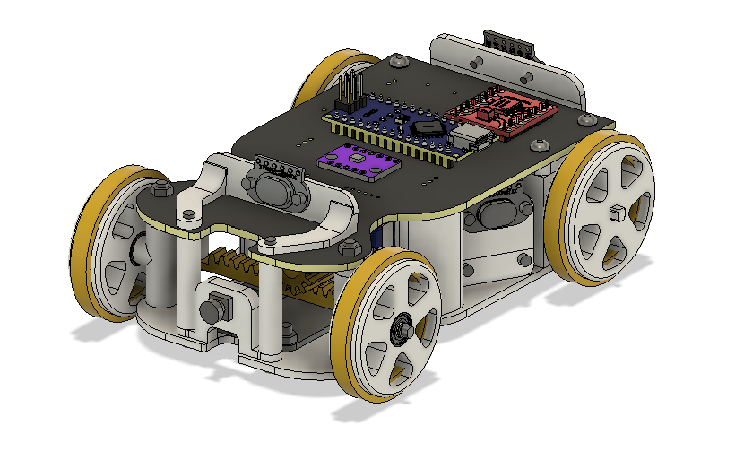
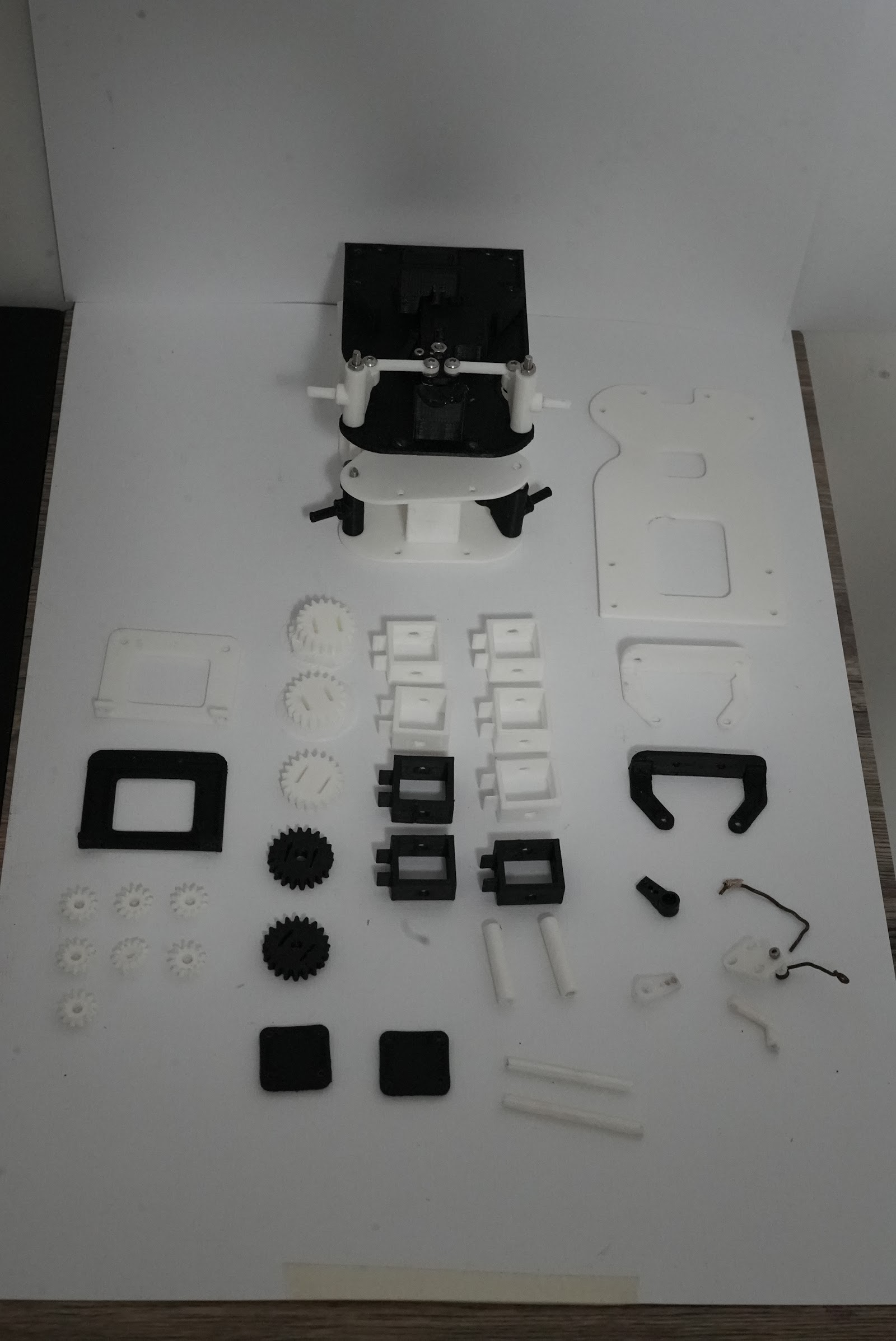
Full CAD assembly of the final car (chassis v3).
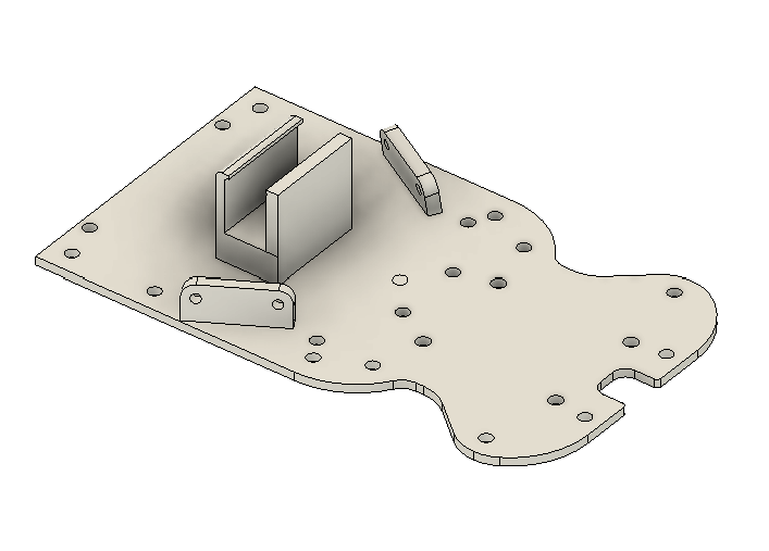 | 1 | 120 × 70 × 23 | Main printed plate: holds the steering at the front, the differential at the rear and the PCB on top |
| [`pcb_big_support_left.stl`](stl/pcb_big_support_left.stl) |
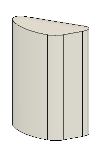 | 1 | 11 × 22 × 28 | Raises the PCB above the drive train (left side) |
| [`pcb_big_support_right.stl`](stl/pcb_big_support_right.stl) |
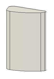 | 1 | 11 × 22 × 28 | Same, right side |
| [`pcb_front_support.stl`](stl/pcb_front_support.stl) |
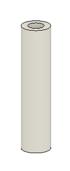 | 2 | 6 × 6 × 26 | Front standoffs for the PCB |
| [`front_spacer.stl`](stl/front_spacer.stl) |
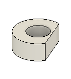 | 2 | 8 × 7 × 3 | Spacers between base and steering parts |
| [`rear_spacer.stl`](stl/rear_spacer.stl) |
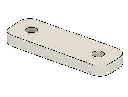 | 1 | 10 × 30 × 3 | Spacer between base and differential support |
### Steering (rack and pinion)
| Part | Render | Qty | Size (mm) | Function |
|---|---|---|---|---|
| [`servo_bracket.stl`](stl/servo_bracket.stl) |
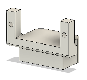 | 1 | 33 × 18 × 23 | Holds the MG90 servo with screws so its case cannot move (the problem of the first SG90 mount) |
| [`steering_gear.stl`](stl/steering_gear.stl) |
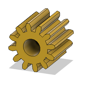 | 1 | Ø 14 × 13 | 12-tooth pinion, module 1 mm, mounted on the servo horn |
| [`gear_rack.stl`](stl/gear_rack.stl) |
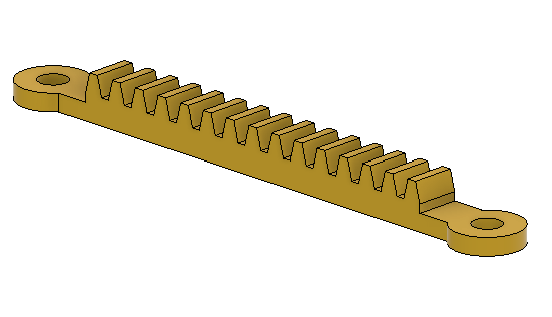 | 1 | 68 × 8 × 5 | Rack, module 1 mm; moves both knuckles together |
| [`left_steering_knuckle.stl`](stl/left_steering_knuckle.stl) |
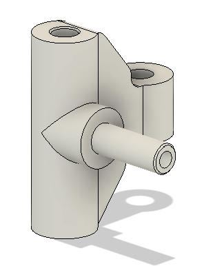 | 1 | 21 × 21 × 25 | Left front wheel pivot |
| [`right_steering_knuckle.stl`](stl/right_steering_knuckle.stl) |
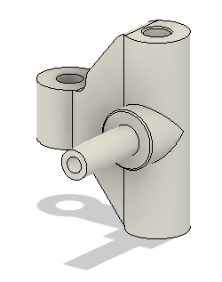 | 1 | 21 × 21 × 25 | Right front wheel pivot |
### Drive train (differential)
| Part | Render | Qty | Size (mm) | Function |
|---|---|---|---|---|
| [`motor_gear.stl`](stl/motor_gear.stl) |
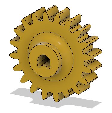 | 1 | Ø 22 × 8 | Gear on the N20 shaft |
| [`motor_restrain.stl`](stl/motor_restrain.stl) |
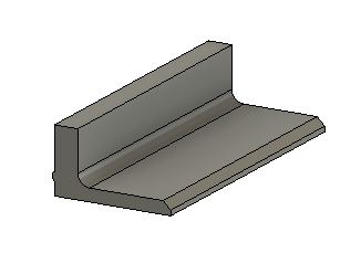 | 1 | 24 × 10 × 6 | Clamp that holds the N20 motor against the base |
| [`differential_support.stl`](stl/differential_support.stl) |
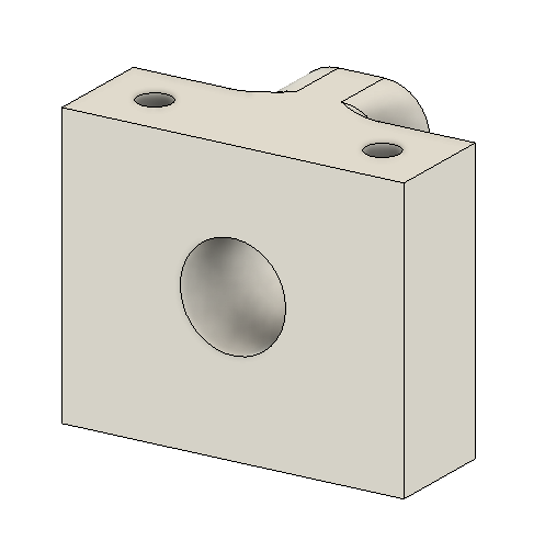 | 1 | 18 × 30 × 25 | Holds the differential and the rear axle |
| [`differential_gear.stl`](stl/differential_gear.stl) |
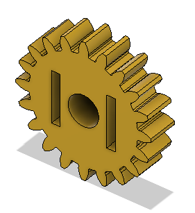 | 1 | Ø 22 × 5 | Ring gear driven 1 : 1 by the motor gear |
| [`differential_box.stl`](stl/differential_box.stl) |
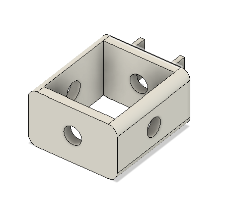 | 1 | 27 × 20 × 12 | Housing of the bevel gears |
| [`diff_bevel_gear.stl`](stl/diff_bevel_gear.stl) |
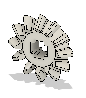 | 4 | Ø 13 × 4 | Bevel gears that let the rear wheels turn at different speeds in corners |
| [`diff_big_axle.stl`](stl/diff_big_axle.stl) |
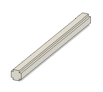 | 1 | 45 × Ø 3.3 | Cross axle of the differential |
| [`diff_small_axle.stl`](stl/diff_small_axle.stl) |
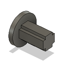 | 2 | 7 × 7 × 7 | Short axles of the spider gears |
### Wheels
| Part | Render | Qty | Size (mm) | Function |
|---|---|---|---|---|
| [`front_wheel.stl`](stl/front_wheel.stl) |
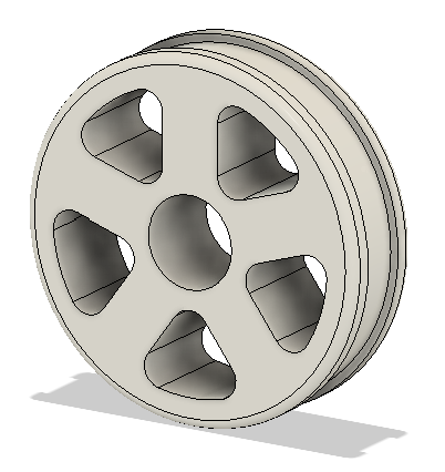 | 2 | Ø 36 × 10 | Front hub; the silicone tyre is cast on it (see [tyres](#4-custom-silicone-tyres)) |
| [`rear_wheel.stl`](stl/rear_wheel.stl) |
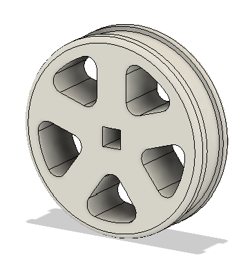 | 2 | Ø 36 × 11 | Rear hub, keyed to the differential output |
### Sensor and camera mounts
| Part | Render | Qty | Size (mm) | Function |
|---|---|---|---|---|
| [`front_sensor_bracket.stl`](stl/front_sensor_bracket.stl) |
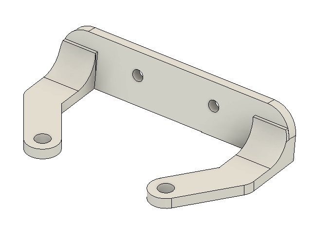 | 1 | 48 × 27 × 10 | Front TOF sensor |
| [`rear_sensor_bracket.stl`](stl/rear_sensor_bracket.stl) |
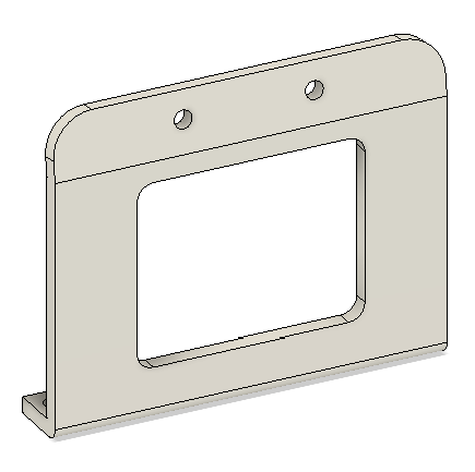 | 1 | 48 × 8 × 39 | Rear TOF sensor |
| [`sensor_bracket.stl`](stl/sensor_bracket.stl) |
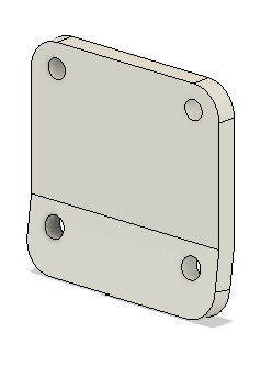 | 2 | 13 × 20 × 22 | Left and right TOF sensors, **1.5 cm higher** than on chassis 1 so the beam no longer passes over the 10 cm wall |
| [`camera_bracket.stl`](stl/camera_bracket.stl) |
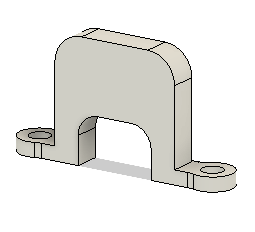 | 1 | 32 × 6 × 17 | OV2640 camera mount, facing forward and slightly down |
> Quantities of 2 or 4 come from the car's symmetry (two side TOF sensors, two front standoffs, four bevel gears in a differential). Check them against the [full CAD](#models--3d-printed-parts-of-enner-valencia) before printing.
### Printing notes
- **Material:** PLA (white and black parts in the photos).
- **Gears (pinion, rack, differential):** print flat on the bed, with a fine layer height so the teeth are clean; they were designed with module 1 mm so the pinion and the rack mesh without filing.
- **Tolerances:** chassis v3 has clearances adjusted so that moving parts (knuckles, rack, gears) turn freely without wobbling. If your printer over-extrudes, test the pinion on the rack before printing everything.
- **Fasteners:** every part of v3 is joined with **screws**; no tape or glue is needed.
---
## 3. Design iterations
| Version | CAD | Printed | Steering | What we learned |
|---|---|---|---|---|
| **v1** |
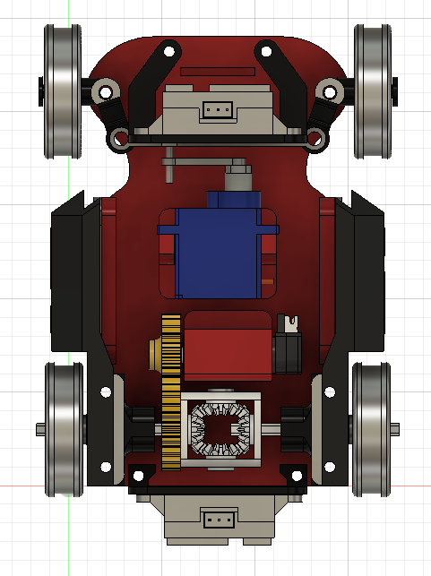 |
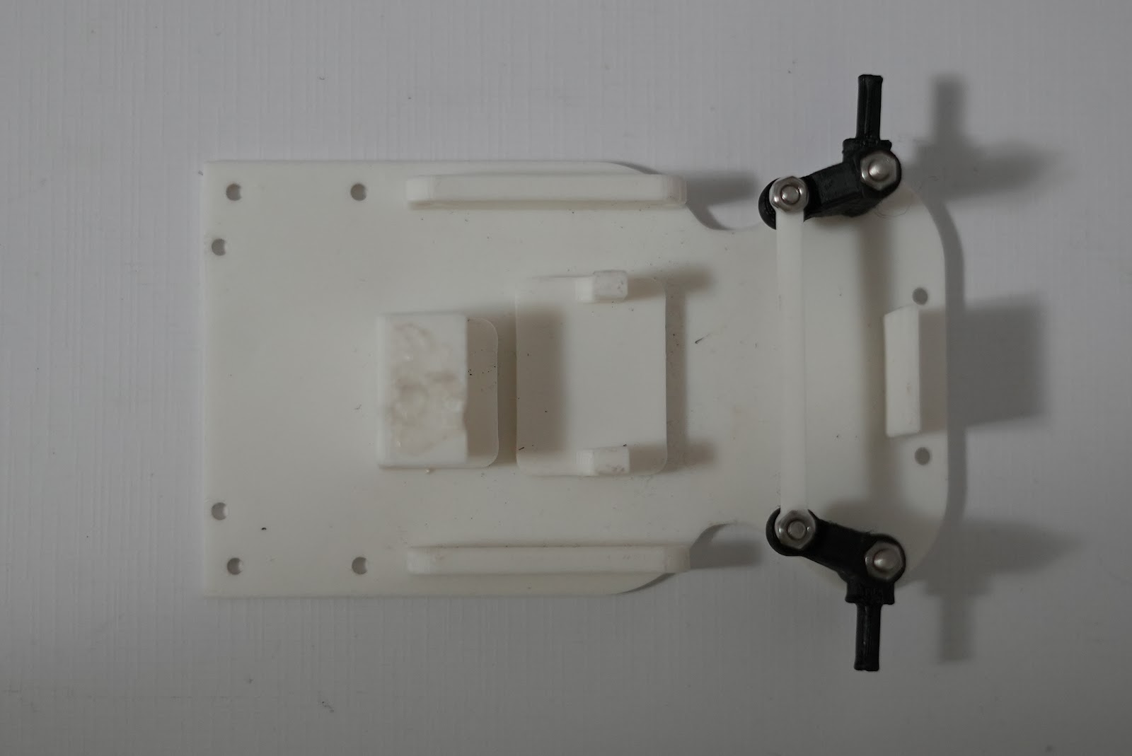 | Classic Ackermann with tie rods | First complete chassis; the SG90 servo moved inside its mount (journal Problem 8) |
| **v2** |
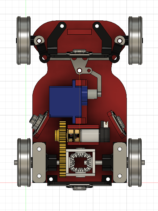 |
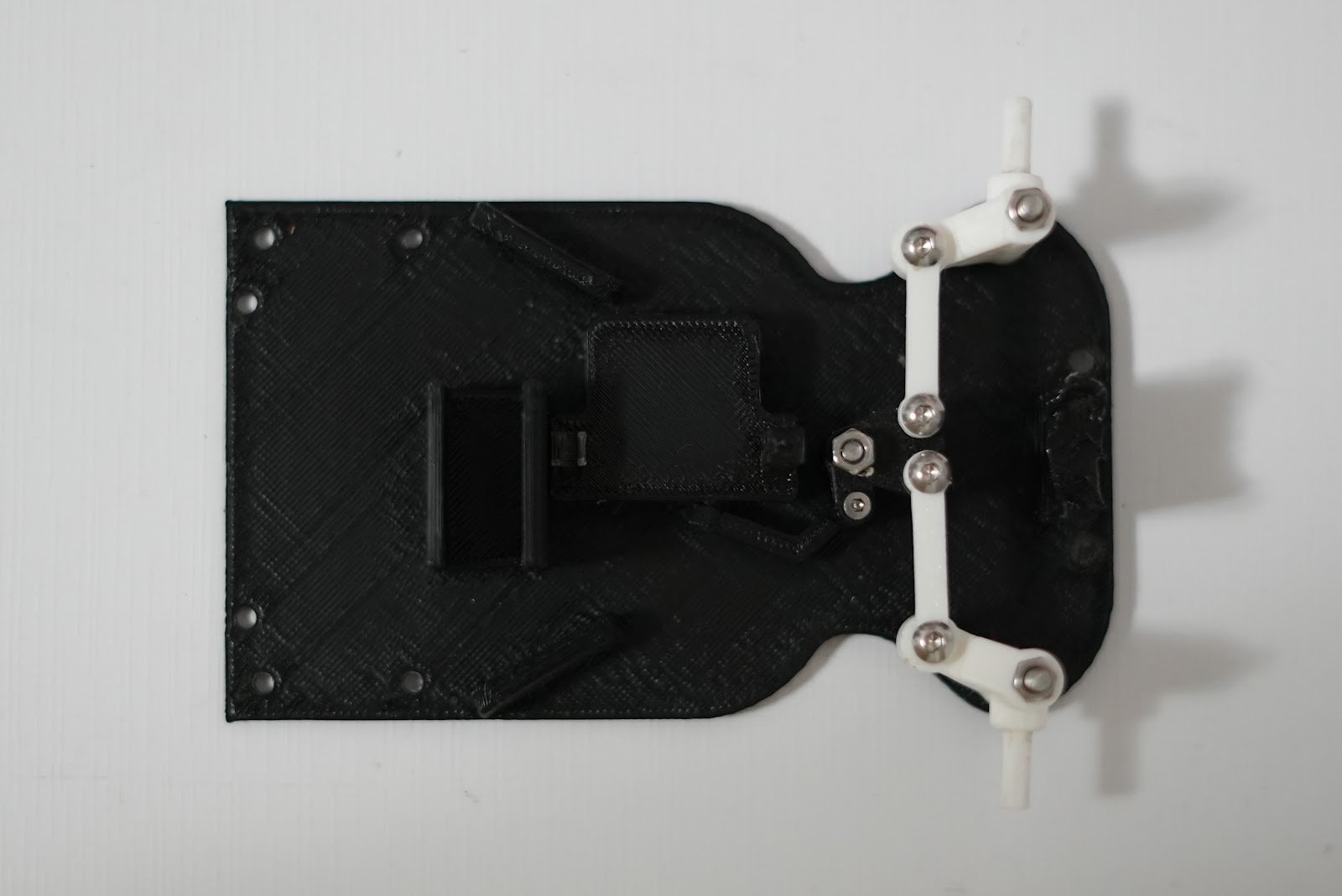 | Ackermann driven by a steering rack | Too much friction in the linkage: the servo could not complete its travel and **three servos were damaged** pushing against it |
| **v3 (final)** |
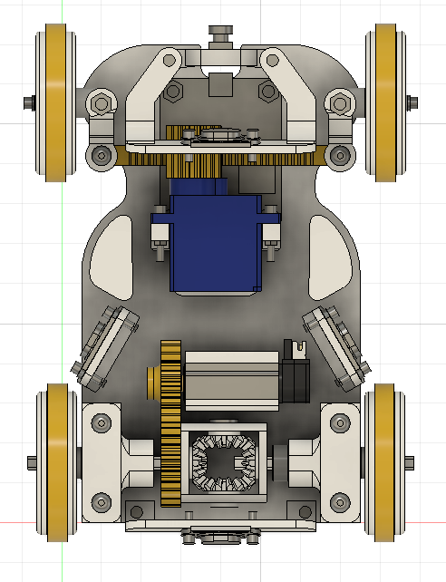 |
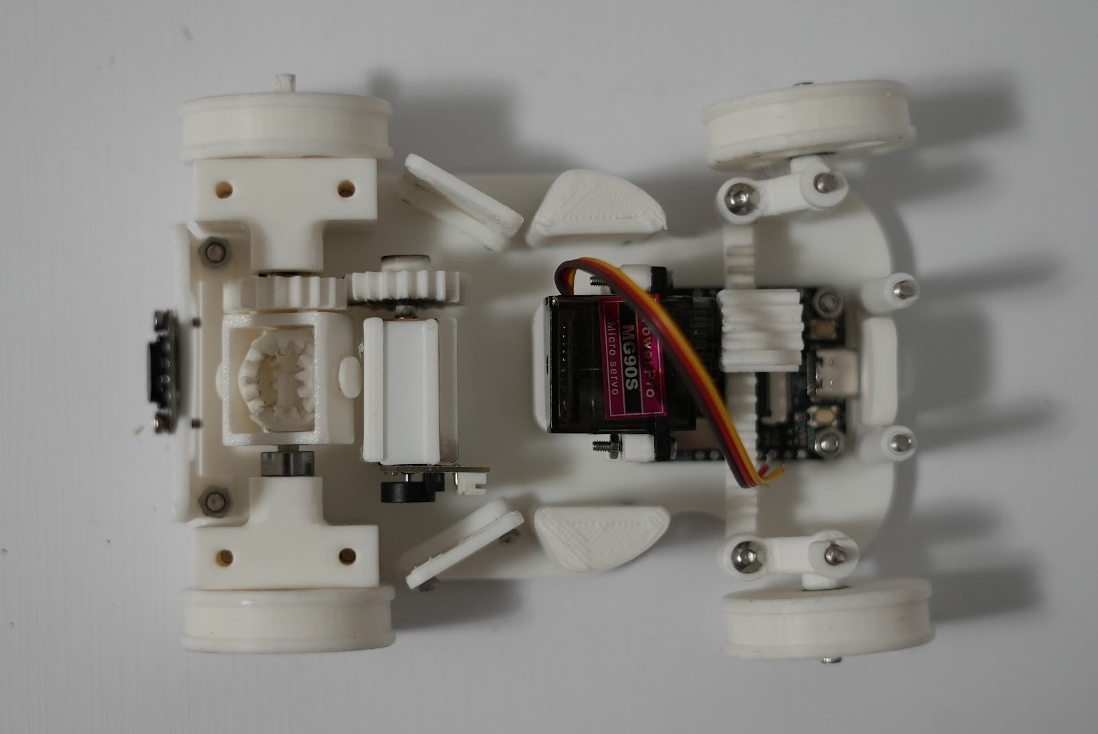 | **Parallel steering with rack and pinion** | Simple, reliable, prints well, nothing is held with tape |
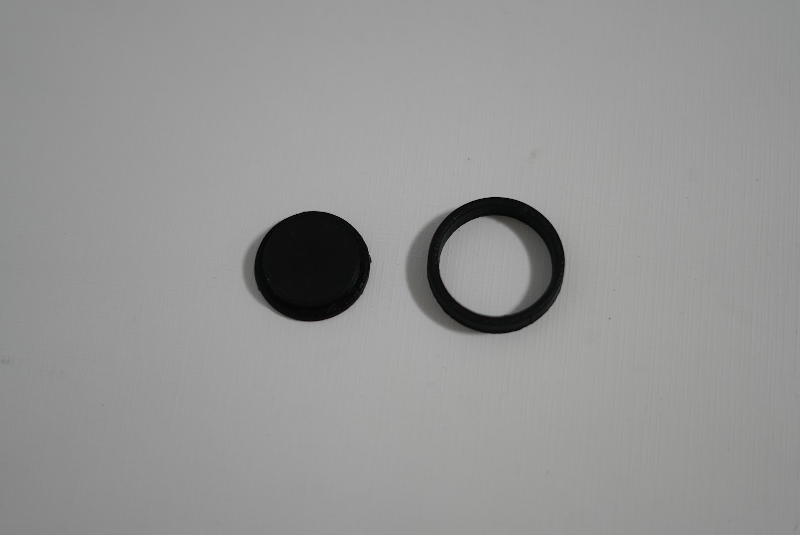
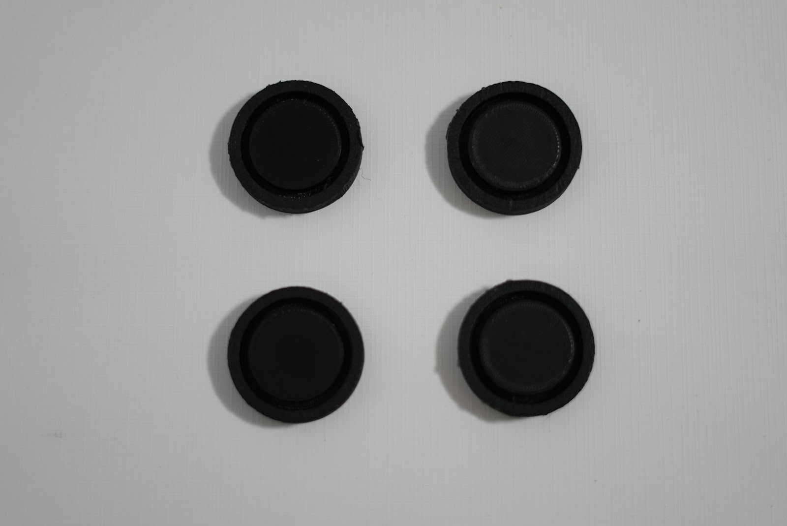 | Print the tyre moulds (the hub sits in the middle, the silicone fills the ring around it) |
| 2. Material |
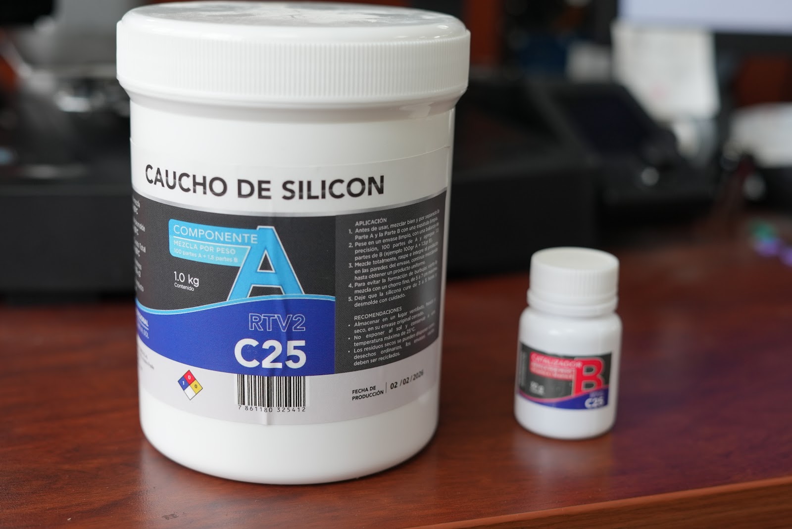 | **C25 silicone rubber**, part A (base) and part B (catalyst) |
| 3. Preparation |
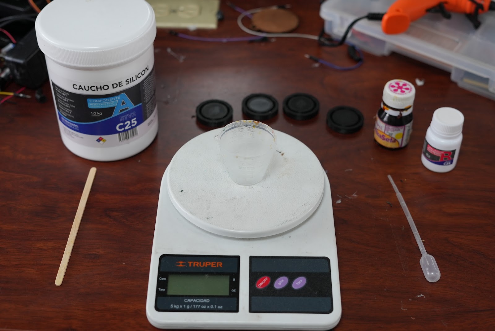 | Scale, cup, stirring stick, dropper and the moulds |
| 4. Weigh part A |
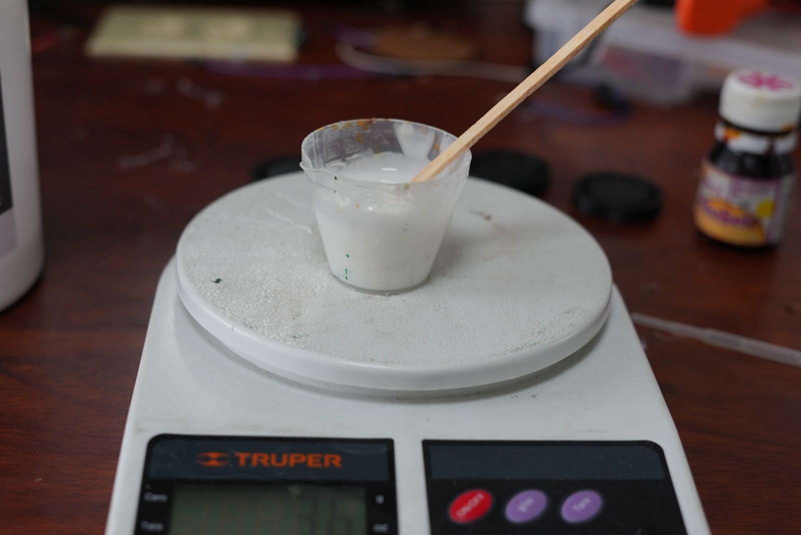 | **30 g** of part A on a gram scale |
| 5. Add part B |
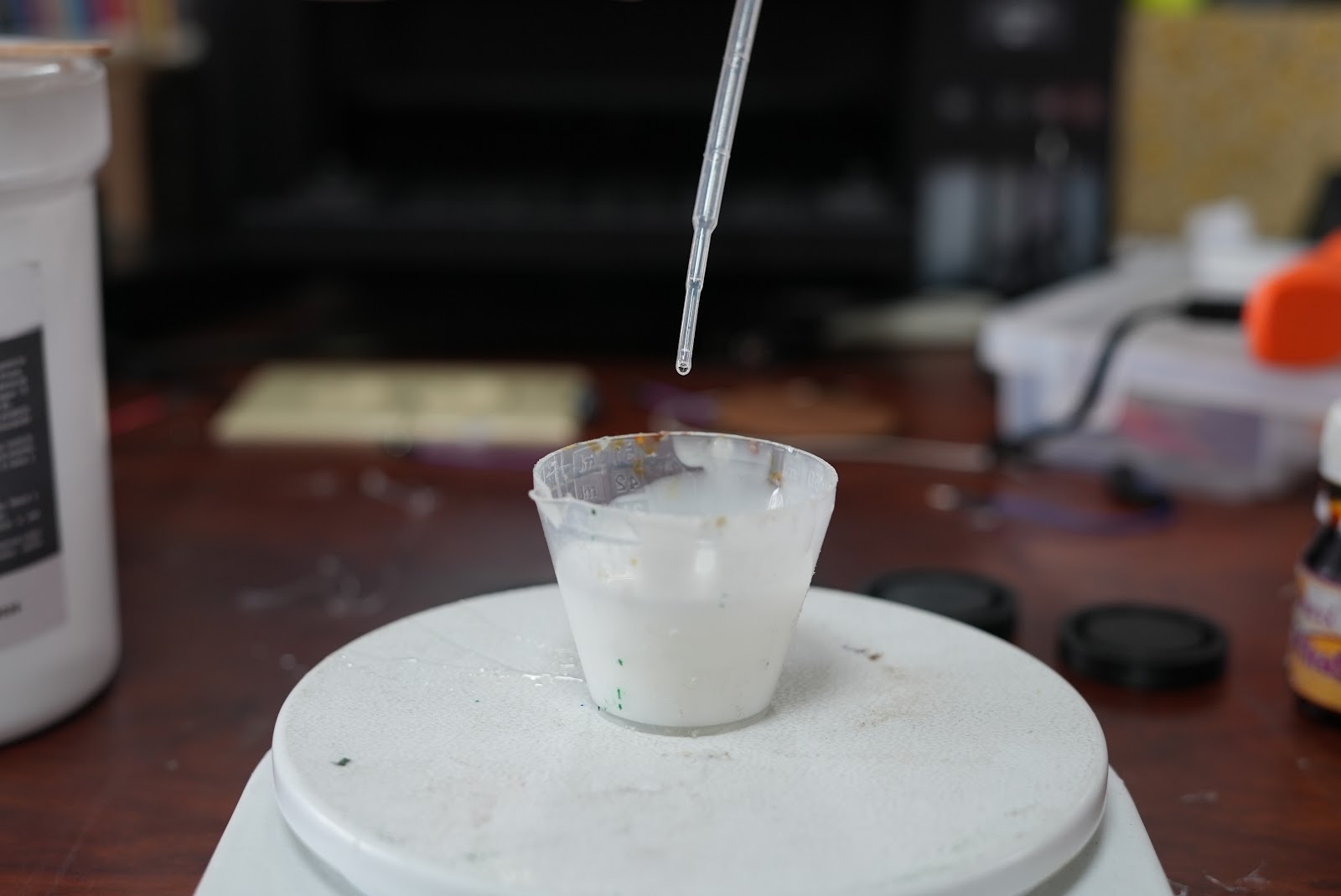 | **23 drops** of part B, from the formula below |
| 6. Mix and pour |
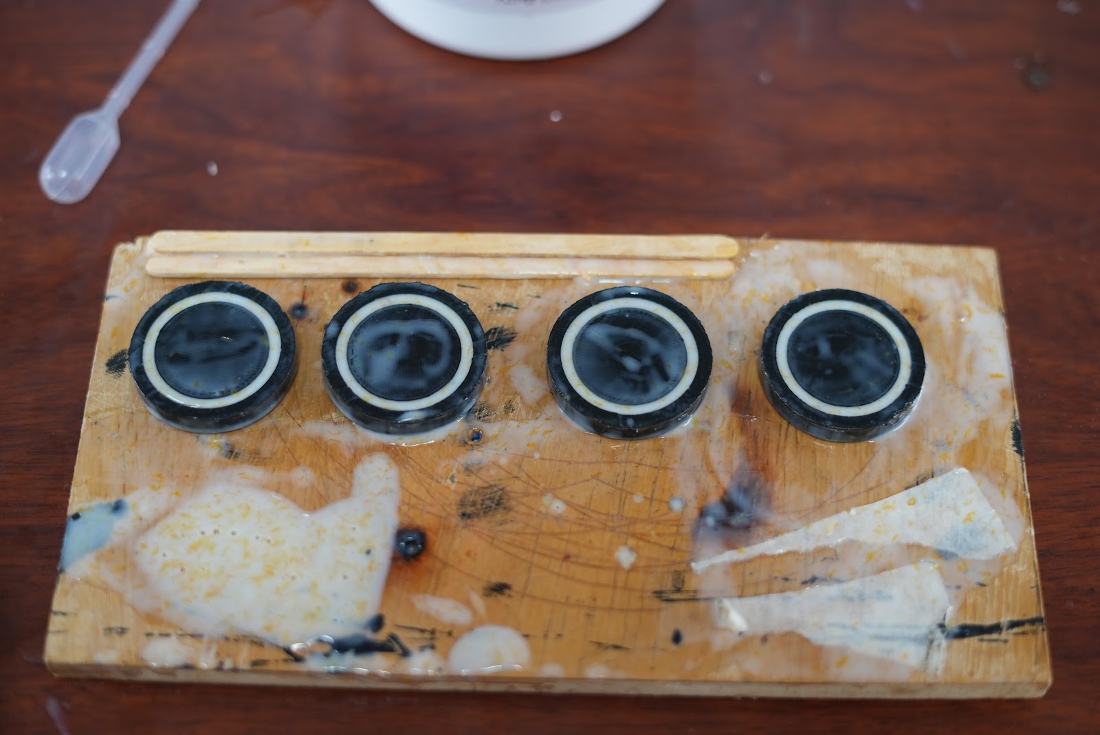 | Mix until most bubbles are gone, then pour into the moulds |
| 7. Cure | — | Wait **5–6 hours** until it is hard, then remove the tyres from the moulds |
**Catalyst formula**
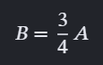 `B = ¾ · A`, where **A** is the mass of part A in grams and **B** the number of drops of part B. For A = 30 g, B = 22.5 → **23 drops**. Using a fixed formula makes every batch cure the same way, so all four tyres have the same hardness and grip.
---
## 5. Assembly order
1. Print all parts (section 2).
2. Cast the four tyres on the hubs (section 4).
3. Mount the N20 motor with `motor_restrain`, then the `differential_support`, the differential and the rear wheels.
4. Screw the `servo_bracket` and the MG90 to the front of the base; fit the pinion on the servo with the servo at its **centre**, then the rack and the two knuckles with the wheels straight.
5. Mount the four TOF brackets and the camera bracket.
6. Fix the PCB on its supports and connect everything following the [wiring diagram](../schemes/README.md#3-wiring-diagram).
7. Run [`servo_calibration`](../src/hardware-tests/servo_calibration) to measure the steering centre and limits before driving.