# Bipedal Self Balancing Robot
 ## Introduction
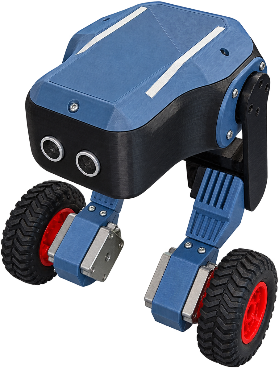
This is a self-balancing robot built from scratch, 3D modeled, PCB designed, 3D printed, wired, and tuned entirely as a personal project. It uses an ESP32 as the main controller, dual IMUs for redundancy, stepper-driven wheels, and 2-DOF legs for lean control.
Right now, it balances for a few seconds at a time. It is not perfect, and there are known issues (see [Problems](#problems) below), but the full design, hardware, and firmware are open source here for anyone who wants to build on it, learn from it, or point out what I got wrong.
**Follow the Journey:** [@kairobyte](https://instagram.com/kairobyte) on Instagram.
## Introduction
This is a self-balancing robot built from scratch, 3D modeled, PCB designed, 3D printed, wired, and tuned entirely as a personal project. It uses an ESP32 as the main controller, dual IMUs for redundancy, stepper-driven wheels, and 2-DOF legs for lean control.
Right now, it balances for a few seconds at a time. It is not perfect, and there are known issues (see [Problems](#problems) below), but the full design, hardware, and firmware are open source here for anyone who wants to build on it, learn from it, or point out what I got wrong.
**Follow the Journey:** [@kairobyte](https://instagram.com/kairobyte) on Instagram.
 ## Sponsors
This build was supported by:
- **[NextPCB](https://www.nextpcb.com/?code=kairobyte)**: PCB manufacturing for this project. Upload your Gerber files, pick your color and thickness, and get an instant quote. Get $30 off your first order.
- **[Axis Tech](https://print3dnepal.com/)**: Provided 3D printing filament for this build. They also offer 3D printing services and build a wide range of custom projects. If you're local, check them out.
[
## Sponsors
This build was supported by:
- **[NextPCB](https://www.nextpcb.com/?code=kairobyte)**: PCB manufacturing for this project. Upload your Gerber files, pick your color and thickness, and get an instant quote. Get $30 off your first order.
- **[Axis Tech](https://print3dnepal.com/)**: Provided 3D printing filament for this build. They also offer 3D printing services and build a wide range of custom projects. If you're local, check them out.
[ ](https://www.nextpcb.com/?code=kairobyte)
[
](https://www.nextpcb.com/?code=kairobyte)
[ ](https://print3dnepal.com/)
## Table of Contents
- [How It Started](#how-it-started)
- [Components](#components)
- [Electronics](#electronics)
- [PCB](#pcb)
- [3D Modelling](#3d-modelling)
- [3D Printing](#3d-printing)
- [Assembly](#assembly)
- [Firmware](#firmware)
- [PID Tuning](#pid-tuning)
- [Problems](#problems)
- [Result](#result)
- [Future Plans](#future-plans)
- [Repository Structure](#repository-structure)
- [License](#license)
## How It Started
- **Idea**: the initial concept for a self-balancing robot.
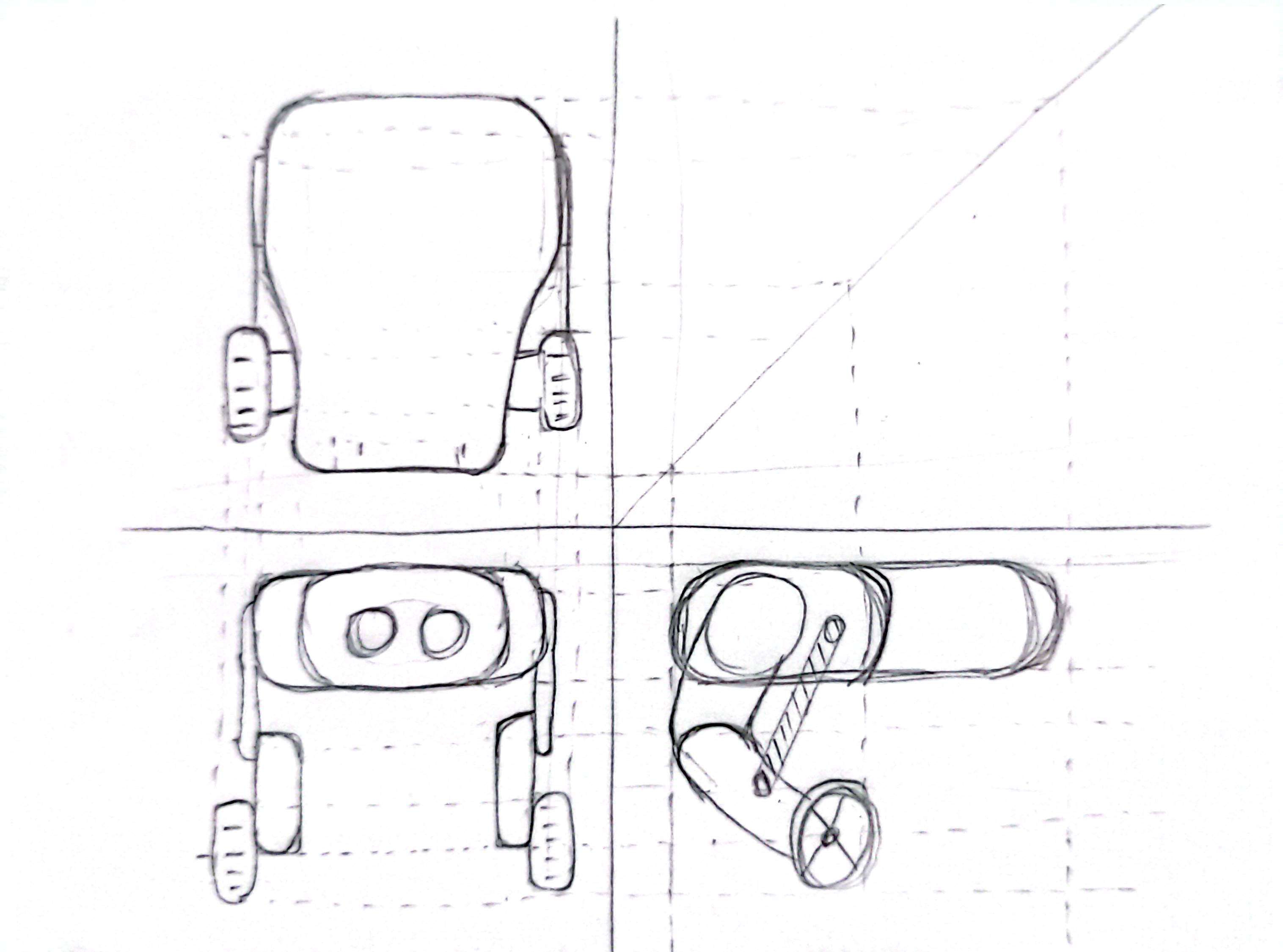
- **Sketch**: a rough hand sketch of the intended design.
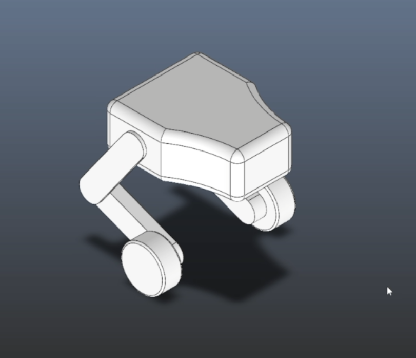
- **Draft 3D Model**: a basic, non-functional 3D model built from the sketch, just for a rough scale and proportion estimate.
](https://print3dnepal.com/)
## Table of Contents
- [How It Started](#how-it-started)
- [Components](#components)
- [Electronics](#electronics)
- [PCB](#pcb)
- [3D Modelling](#3d-modelling)
- [3D Printing](#3d-printing)
- [Assembly](#assembly)
- [Firmware](#firmware)
- [PID Tuning](#pid-tuning)
- [Problems](#problems)
- [Result](#result)
- [Future Plans](#future-plans)
- [Repository Structure](#repository-structure)
- [License](#license)
## How It Started
- **Idea**: the initial concept for a self-balancing robot.
- **Sketch**: a rough hand sketch of the intended design.
- **Draft 3D Model**: a basic, non-functional 3D model built from the sketch, just for a rough scale and proportion estimate.
 ## Components
- **ESP32**: main controller.
- **MPU6050 + MPU9250**: dual IMUs, used for sensor redundancy.
- **A4988 Driver**: used to control the stepper motors.
- **Stepper motors**: used for wheel drive.
> **Note:** If you're building something similar, I would not recommend steppers for the wheels. Go with high-torque BLDC motors instead. Steppers work, but they're not the ideal choice here.
## Electronics
- Two buck converters step down 12V from a 3S LiPo battery, one dedicated to sensors, one dedicated to servos, to keep noisy current draw away from sensor power.
- A capacitor and diode protect the ESP32 from brownouts during high current draw from the servos and steppers.
## PCB
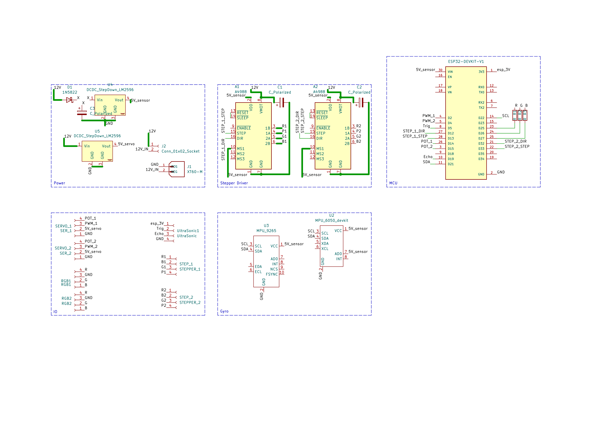
- Selected footprints and components, then built out the full schematic with labeled nets for readability.
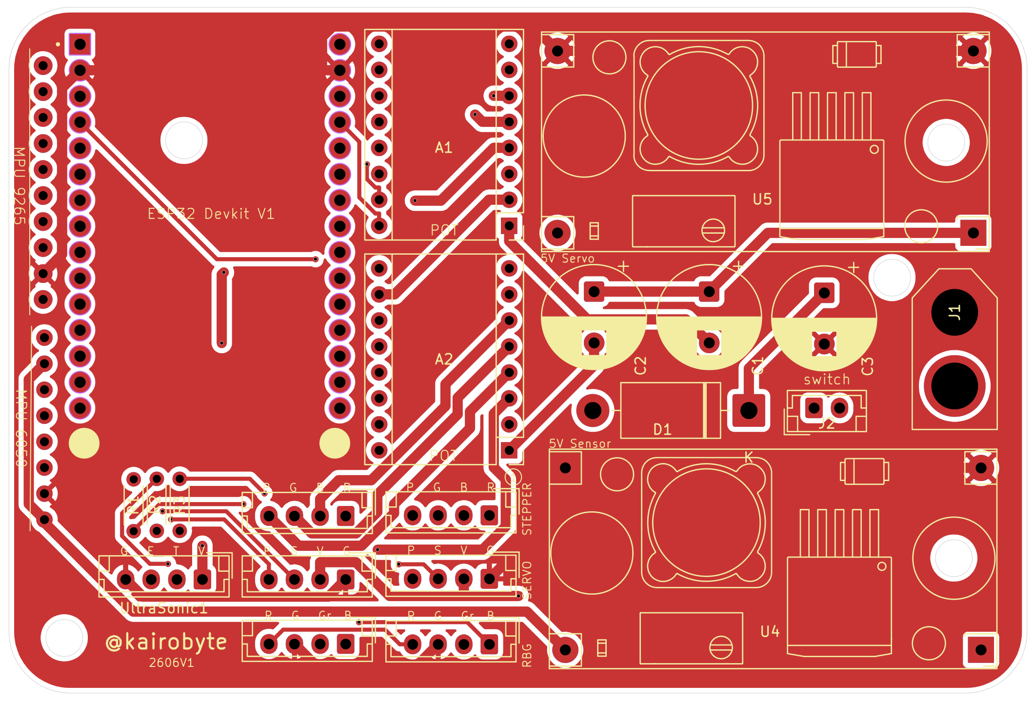
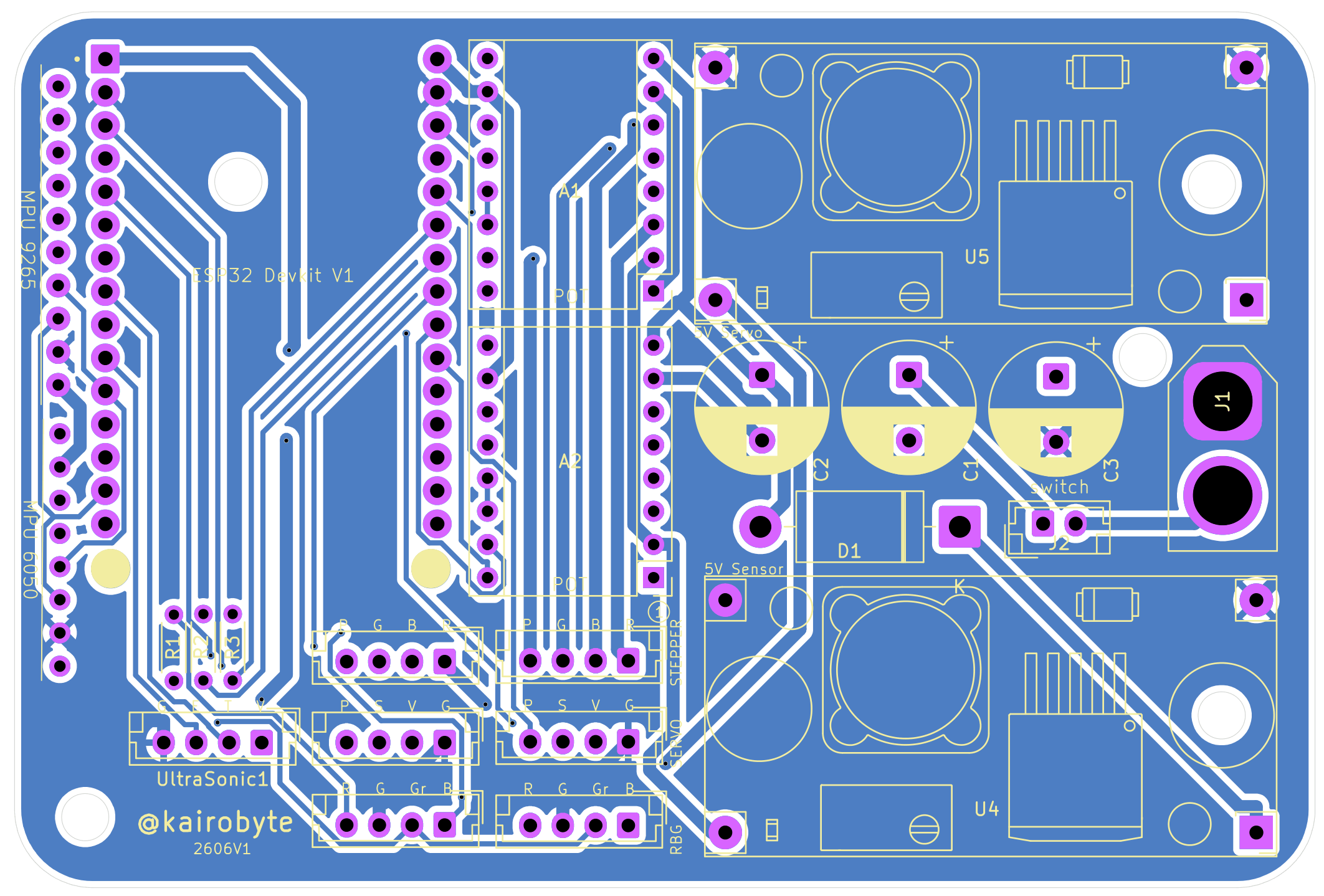
- Completed layout and routing.
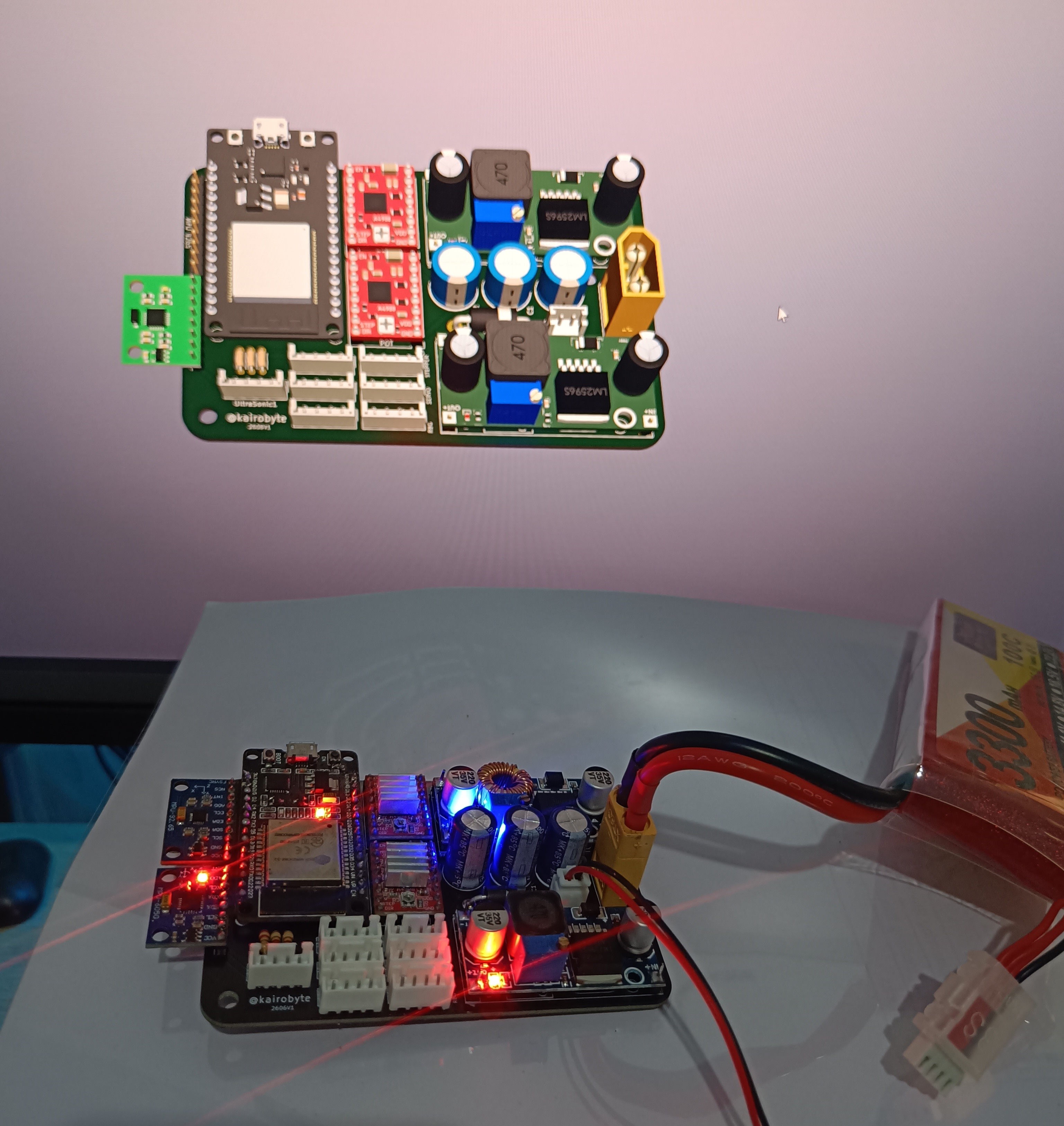
- Ran the Design Rule Checker (DRC), exported Gerber files, and had the board manufactured through [NextPCB](https://www.nextpcb.com/?code=kairobyte).
## Components
- **ESP32**: main controller.
- **MPU6050 + MPU9250**: dual IMUs, used for sensor redundancy.
- **A4988 Driver**: used to control the stepper motors.
- **Stepper motors**: used for wheel drive.
> **Note:** If you're building something similar, I would not recommend steppers for the wheels. Go with high-torque BLDC motors instead. Steppers work, but they're not the ideal choice here.
## Electronics
- Two buck converters step down 12V from a 3S LiPo battery, one dedicated to sensors, one dedicated to servos, to keep noisy current draw away from sensor power.
- A capacitor and diode protect the ESP32 from brownouts during high current draw from the servos and steppers.
## PCB
- Selected footprints and components, then built out the full schematic with labeled nets for readability.
- Completed layout and routing.
- Ran the Design Rule Checker (DRC), exported Gerber files, and had the board manufactured through [NextPCB](https://www.nextpcb.com/?code=kairobyte).
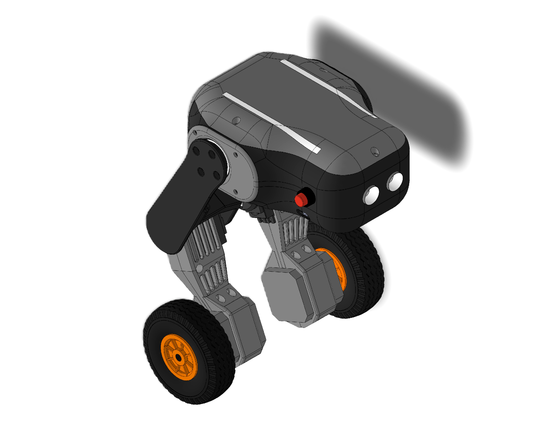
 ## 3D Modelling
- Modeled in SolidWorks, built bottom-up: stepper holders → legs → base.
- Every part was broken down into basic shapes and built up gradually.
- Designing for 3D printability is a different skill from designing for looks, significant time went into optimizing parts for print rather than just appearance.
## 3D Modelling
- Modeled in SolidWorks, built bottom-up: stepper holders → legs → base.
- Every part was broken down into basic shapes and built up gradually.
- Designing for 3D printability is a different skill from designing for looks, significant time went into optimizing parts for print rather than just appearance.
 ## 3D Printing
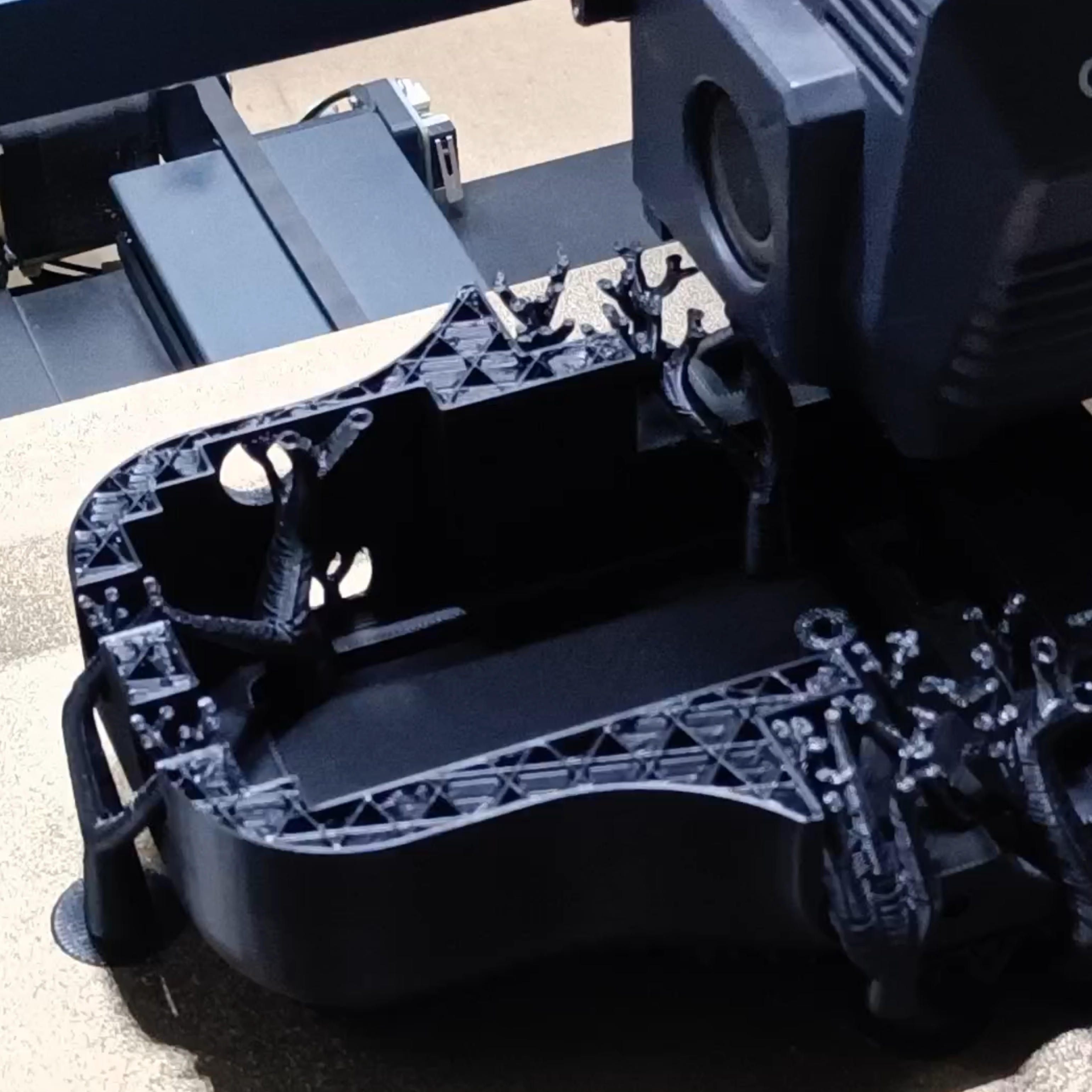
- Parts were prepared and arranged in the slicer, then printed over several days.
- Most parts fit together correctly on the first attempt.
- Thanks [Axis Tech](https://print3dnepal.com/) for the Filament Support!
## 3D Printing
- Parts were prepared and arranged in the slicer, then printed over several days.
- Most parts fit together correctly on the first attempt.
- Thanks [Axis Tech](https://print3dnepal.com/) for the Filament Support!
 ## Assembly
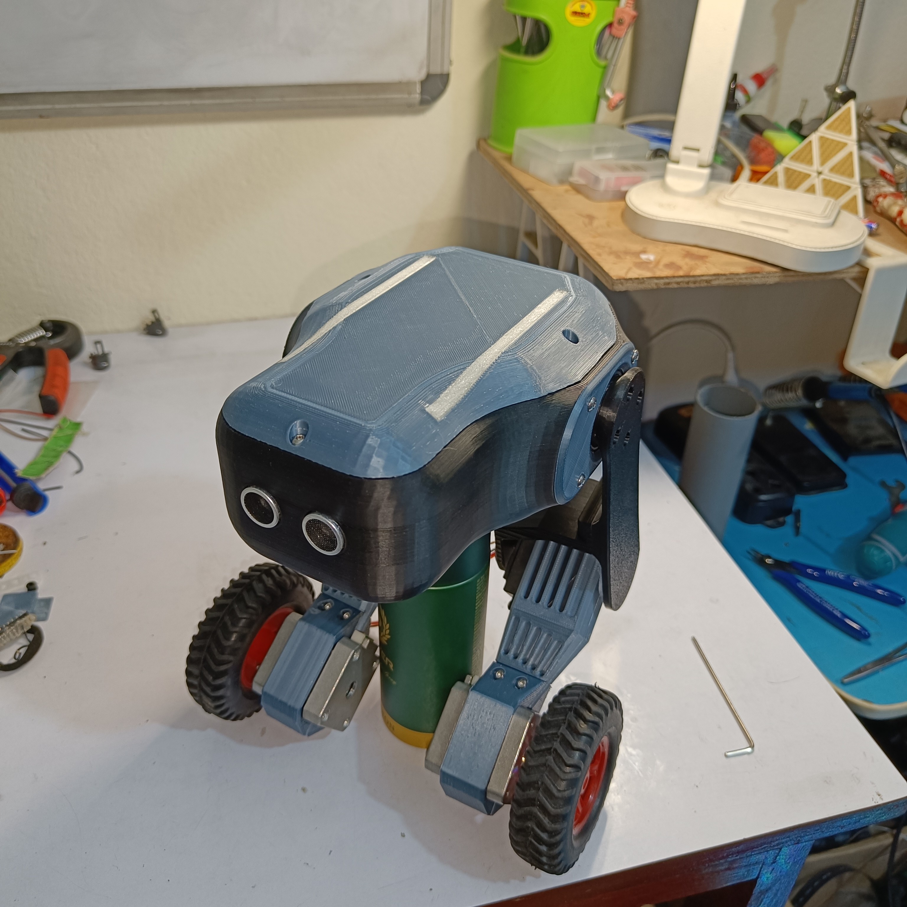
- Assembled all 3D printed parts and completed the wiring.
- The original plan was for 1 degree of freedom (DOF) per leg. When this changed to 2 DOF, extra wires had to be soldered directly onto the ESP32.
> **If you're building this yourself:** finalize your degrees of freedom before finalizing your board layout, to avoid needing extra hand-soldered connections.
## Assembly
- Assembled all 3D printed parts and completed the wiring.
- The original plan was for 1 degree of freedom (DOF) per leg. When this changed to 2 DOF, extra wires had to be soldered directly onto the ESP32.
> **If you're building this yourself:** finalize your degrees of freedom before finalizing your board layout, to avoid needing extra hand-soldered connections.
 ## Firmware
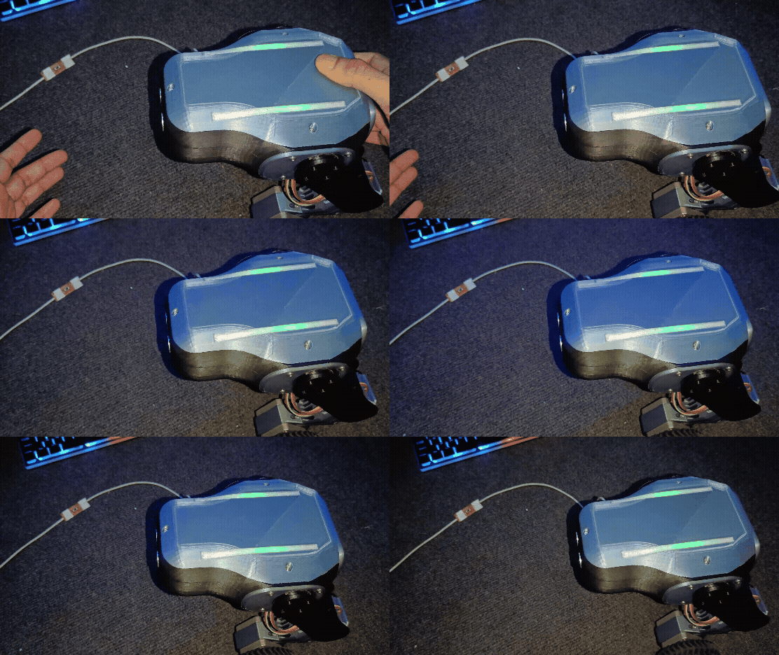
- Ran initial test code to confirm all motors, sensors, and RGB indicators were functioning correctly.
- Built a basic PID controller as the first control approach.
- Due to the robot's irregular shape, finding the correct center of mass, and therefore the correct PID set point, was one of the most time-consuming parts of the build.
## PID Tuning
Tuning was the hardest part of this project by a significant margin.
- Initially tuned by manually guessing parameters and reflashing the ESP32 for every change, slow and impractical.
- Updated the firmware to accept tuning parameters over serial and save them without requiring a reflash. A WiFi-based version was attempted but caused repeated ESP32 brownout warnings, so serial was used instead.
- After a couple of days with no visible progress, found that one servo was vibrating irregularly and injecting significant noise into the sensor readings. Replacing that servo noticeably improved stability, though it wasn't a complete fix.
- After continued tuning, the robot balanced for the first time, for a few seconds.
- Found that linear gain increments were not effective, and switched to exponentially increasing gains, along with a low-pass filter applied to key parameters. This slowed the robot's reaction time somewhat, but the control loop still ran at approximately 1kHz, which was fast enough to remain effective.
- Total PID tuning time was a little over a week, including a short break after becoming frustrated with a lack of progress.
## Problems
- **Servo speed**: current servos aren't fast enough to keep up with PID output; the actuator consistently lags behind the commanded position. Needs a faster servo, or a BLDC motor with gear reduction.
- **PID tuning method**: manually guessing parameters is slow and inefficient; a more systematic tuning approach would be better.
- **Vibration/noise**: servo vibration was a major source of sensor noise and nearly derailed the project. Replacing the affected servo helped significantly.
- **Electronics/compute headroom**: the ESP32 currently handles the full control loop, but adding Bluetooth communication (for planned PS4 controller support) is expected to consume enough clock cycles to slow down the PID loop. A better long-term architecture would use a dedicated microcontroller (e.g. STM32) for the core PID loop, with the ESP32 handling WiFi/Bluetooth communication separately, connected via UART.
- **Noise/sensing**: relying on a single sensing source is fragile. A low-pass filter helps smooth spikes, and vibration-dampening rubber mounts can reduce mechanical noise from the steppers.
## Result
The robot currently balances for a few seconds before losing stability. It is a working proof of concept, not a finished product, further tuning and hardware changes are planned for the next phase of this build.
## Future Plans
- **PS4 controller integration** over Bluetooth.
- **Machine learning-based balancing**: exploring whether an ML approach could replace or supplement the PID controller. This is unexplored territory for this project so far.
Follow along on Instagram for more frequent build updates.
## Repository Structure
```
├── 1. 3D_Model # SolidWorks source files and exported STLs
├── 2. PCB_Design # Schematic, PCB layout, and Gerber files
├── 3. Code # ESP32 source code
├── 4. Assets # Images used in this README
├── LICENSE
└── README.md
```
## License
This project is open source under the MIT license. See `LICENSE` for details.
##
Send a mail if you want to discuss robotics, design, engineering projects, or anything you think I should build next.
[mail@sushant.uk](mailto:mail@sushant.uk)
## Firmware
- Ran initial test code to confirm all motors, sensors, and RGB indicators were functioning correctly.
- Built a basic PID controller as the first control approach.
- Due to the robot's irregular shape, finding the correct center of mass, and therefore the correct PID set point, was one of the most time-consuming parts of the build.
## PID Tuning
Tuning was the hardest part of this project by a significant margin.
- Initially tuned by manually guessing parameters and reflashing the ESP32 for every change, slow and impractical.
- Updated the firmware to accept tuning parameters over serial and save them without requiring a reflash. A WiFi-based version was attempted but caused repeated ESP32 brownout warnings, so serial was used instead.
- After a couple of days with no visible progress, found that one servo was vibrating irregularly and injecting significant noise into the sensor readings. Replacing that servo noticeably improved stability, though it wasn't a complete fix.
- After continued tuning, the robot balanced for the first time, for a few seconds.
- Found that linear gain increments were not effective, and switched to exponentially increasing gains, along with a low-pass filter applied to key parameters. This slowed the robot's reaction time somewhat, but the control loop still ran at approximately 1kHz, which was fast enough to remain effective.
- Total PID tuning time was a little over a week, including a short break after becoming frustrated with a lack of progress.
## Problems
- **Servo speed**: current servos aren't fast enough to keep up with PID output; the actuator consistently lags behind the commanded position. Needs a faster servo, or a BLDC motor with gear reduction.
- **PID tuning method**: manually guessing parameters is slow and inefficient; a more systematic tuning approach would be better.
- **Vibration/noise**: servo vibration was a major source of sensor noise and nearly derailed the project. Replacing the affected servo helped significantly.
- **Electronics/compute headroom**: the ESP32 currently handles the full control loop, but adding Bluetooth communication (for planned PS4 controller support) is expected to consume enough clock cycles to slow down the PID loop. A better long-term architecture would use a dedicated microcontroller (e.g. STM32) for the core PID loop, with the ESP32 handling WiFi/Bluetooth communication separately, connected via UART.
- **Noise/sensing**: relying on a single sensing source is fragile. A low-pass filter helps smooth spikes, and vibration-dampening rubber mounts can reduce mechanical noise from the steppers.
## Result
The robot currently balances for a few seconds before losing stability. It is a working proof of concept, not a finished product, further tuning and hardware changes are planned for the next phase of this build.
## Future Plans
- **PS4 controller integration** over Bluetooth.
- **Machine learning-based balancing**: exploring whether an ML approach could replace or supplement the PID controller. This is unexplored territory for this project so far.
Follow along on Instagram for more frequent build updates.
## Repository Structure
```
├── 1. 3D_Model # SolidWorks source files and exported STLs
├── 2. PCB_Design # Schematic, PCB layout, and Gerber files
├── 3. Code # ESP32 source code
├── 4. Assets # Images used in this README
├── LICENSE
└── README.md
```
## License
This project is open source under the MIT license. See `LICENSE` for details.
##
Send a mail if you want to discuss robotics, design, engineering projects, or anything you think I should build next.
[mail@sushant.uk](mailto:mail@sushant.uk)