
| 2024 Season Competition Self-Driving Car Prototype | 2025 WRO World Final Competition Prototype | |
|---|---|---|
 |
 |
 |
| Description | ||
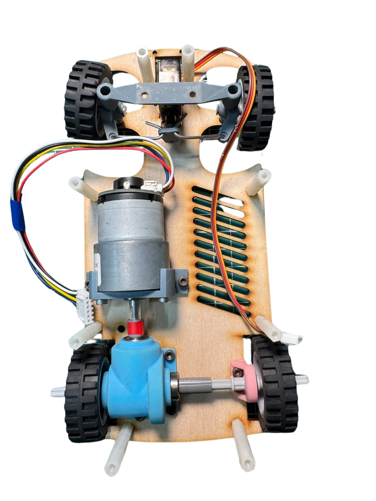
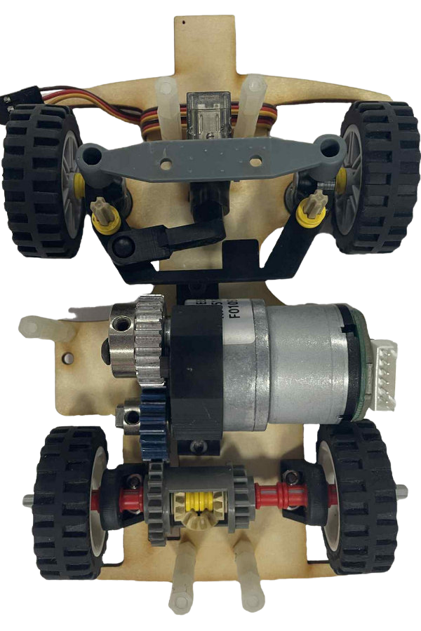
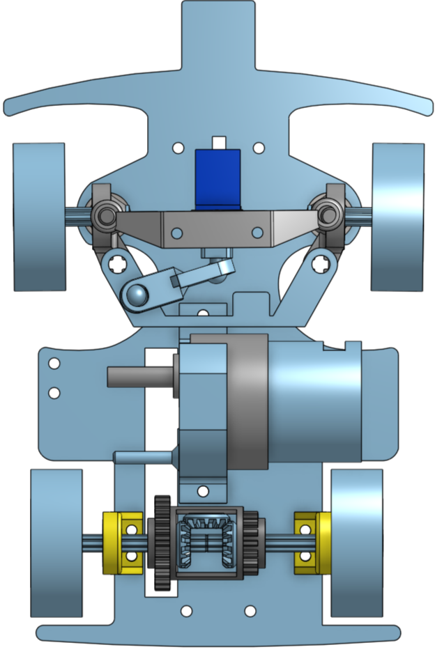
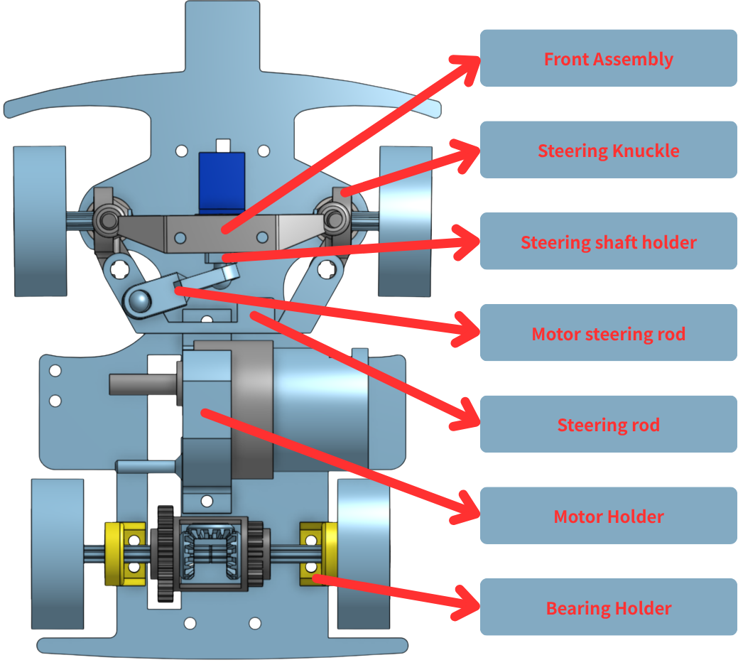
| #### **Major Changes in Model and Functionality** From the previous year's version to this year's international competition version, our model design underwent several key optimizations: * **Model Size Optimization:** Since the vehicle model was too long, it frequently **moved the field pillars/blocks during obstacle avoidance**. We **shortened the overall length of the model** to enhance obstacle clearance stability. * **Main Controller Upgrade:** During the National Competition, we found that the **Jetson Nano's computing efficiency** was insufficient for our needs. Consequently, we replaced the main controller with the **higher-computing-efficiency Jetson Orin Nano**. * **Steering Structure Redesign (I):** Last year's international model used **metal wires** to link the two steering knuckles, which **occupied a large area** and was inefficient. We therefore **redesigned the entire steering structure using 3D printed components**. * **Steering Structure Redesign (II):** The autonomous vehicle's **steering angle was insufficient**, preventing it from navigating certain **sharp turns**. We **redesigned the steering structure** to allow for a **larger steering space**, enhancing its maneuverability. * **Addition of Parking Assistance Sensors:** We **added TCRT5000 infrared sensors to the front and rear** of the vehicle, specifically dedicated to **assisting the precision of the parking procedure**. #### **The Four Iterations of Chassis Design** Our chassis design underwent a total of four iterations: 1. **First Iteration:** **Arc-shaped chamfers** were added to the front of the car to prevent the front wheels from **getting stuck** when contacting the side walls, improving self-extrication capabilities after collision. 2. **Second Iteration:** We **enlarged the mounting holes for the steering knuckles** and **switched to using bearings** to reduce friction, making the steering process **smoother**. 3. **Third Iteration:** We **reduced the gap** between the steering structure and the motor brackets, and **shortened the wheelbase** to **increase the steering angle** (reducing the turning radius). 4. **Fourth Iteration:** A **small rectangular block was extended** from the front of the car, specifically to **protect the infrared sensors** from damage during wall collisions. | ||
 ||
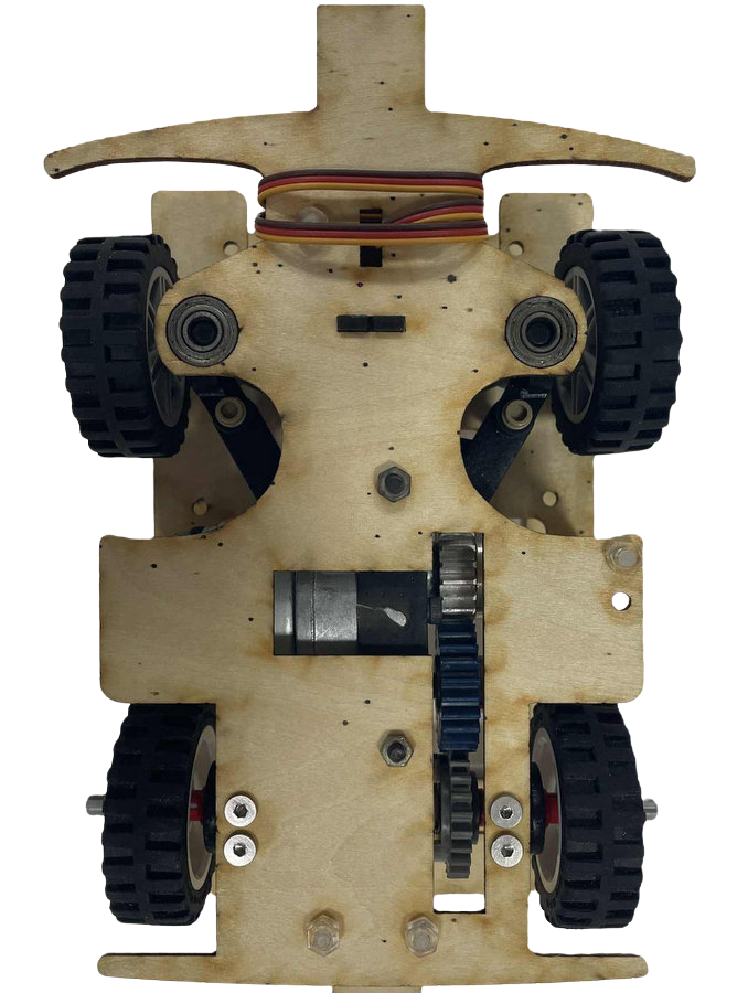 |
- We customized the design of component dimensions and shapes based on the specific performance requirements of the autonomous vehicle. Utilizing a Stereolithography (SLA) 3D printer and a laser cutting machine, we self-designed and manufactured all parts of the vehicle chassis, excluding the gears, the LEGO 6573 differential gear, and the tires.
- To significantly reduce the rotational friction of the bearings, we - precisely integrated them into the vehicle's support structure (bracket), a mechanical optimization that effectively enhanced the vehicle's overall driving speed.
- In order to precisely control the vehicle's optimal turning radius and flexibly adjust the Ackermann ratio, we employed 3D modeling techniques and a Stereolithography (SLA) 3D printer to custom-design the critical components and vehicle brackets for the Ackermann steering geometry structure according to specific needs.
**Evolution of the Ackermann Steering Geometry Structure**
| First Generation Steering Structure (V1.0) | |
|---|---|
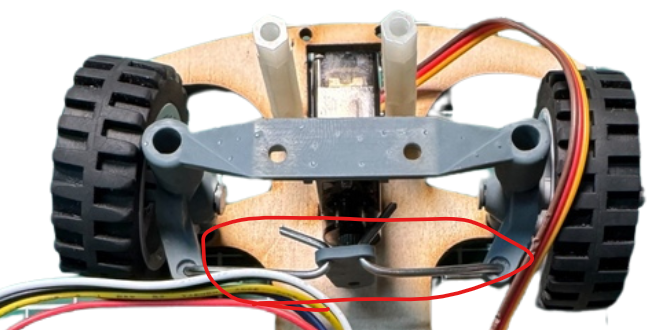 |
This version of the steering structure was designed to be overly wide, and the steering rod was made from drawn metal wire, which was difficult to fix into shape, impacting accuracy. |
| Second Generation Steering Structure (V2.0) | |
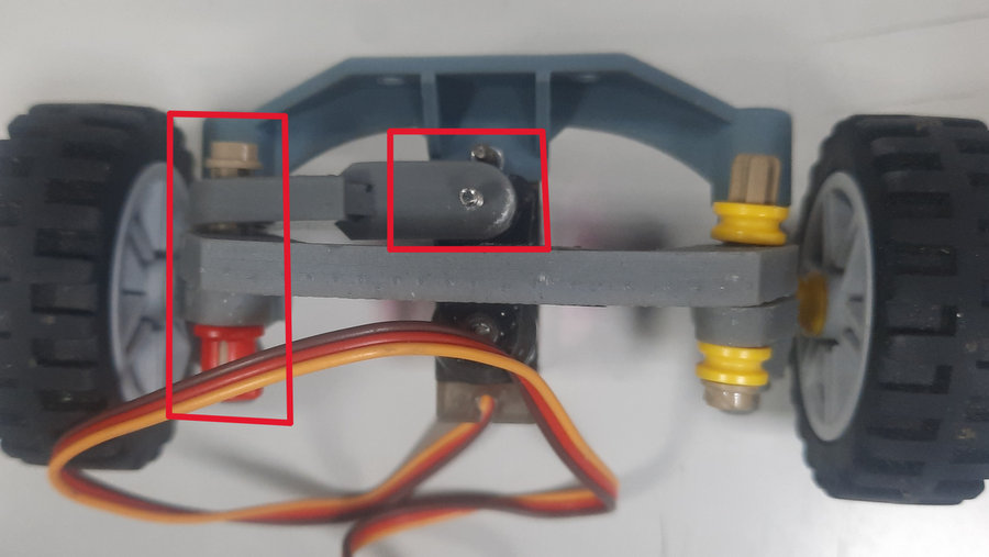 |
To solve the V1.0 structure's bulkiness and accuracy issues, in V2.0 we: - Reduced the overall template size. - Replaced the metal wire steering rod with a 3D printed component, significantly improving the rod's accuracy and enhancing the self-driving car's steering agility. However, the use of screws to connect LEGO parts in this version still constrained the steering angle. Therefore, the next iteration (V3.0) will switch to rounded cross axles and Ball Joint Steering Shaft Holder to increase the steering range. |
| Third Generation Steering Structure (V3.0) | |
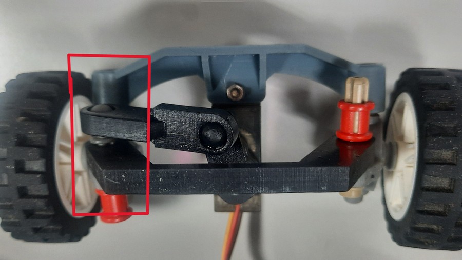 |
This version encountered steering torque issues during testing, leading us to re-examine the design blueprint. The next version (V4.0) will incorporate the following fixes: - Adjust the connection point of the steering tie rod and linkage to be parallel with the rounded steering rack, optimizing mechanical performance. - Add a steering limit block to prevent the structure from collapsing inwards due to excessive steering angles. |
| Fourth Generation Steering Structure (V4.0) | |
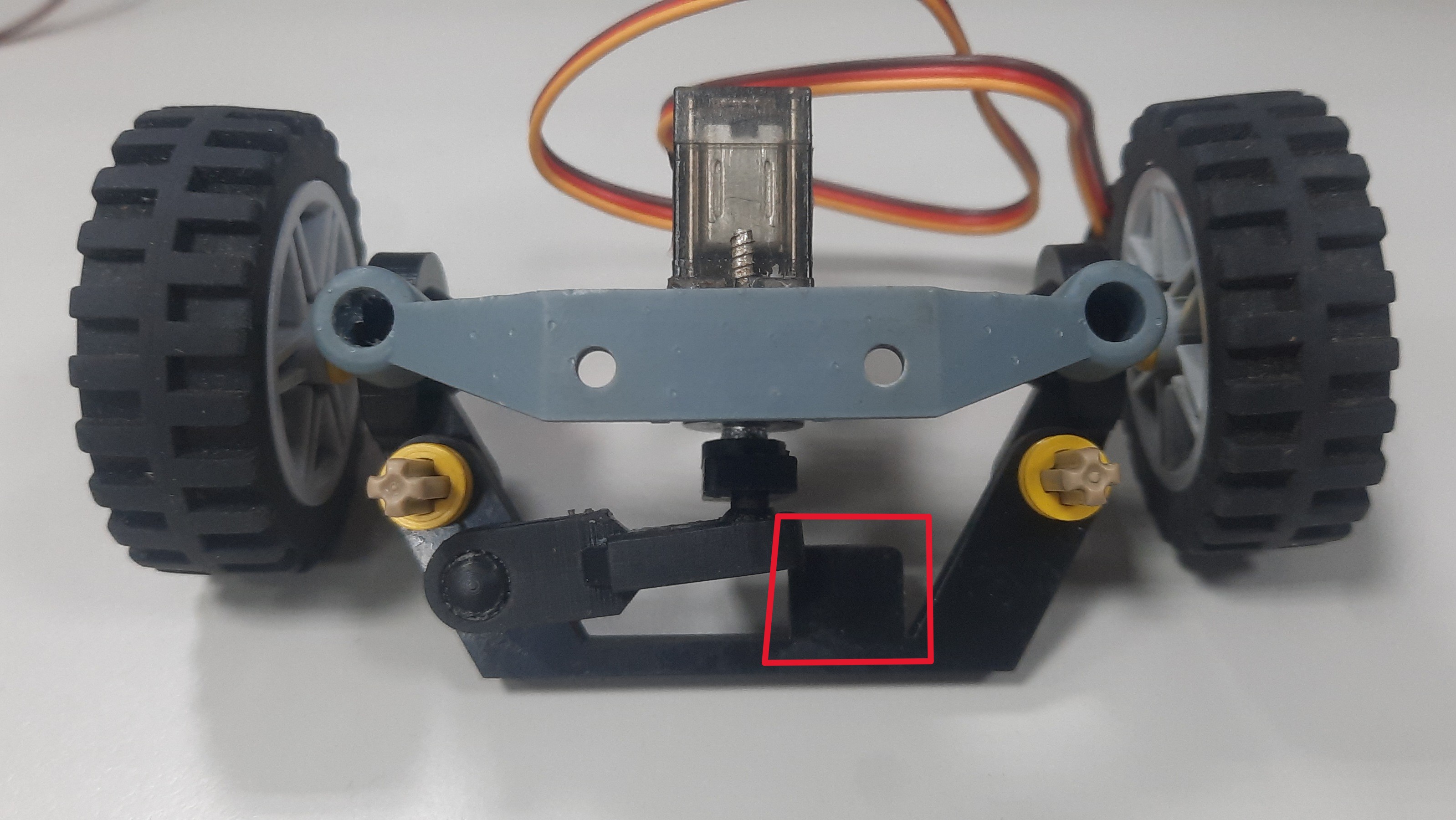 |
The newly added steering limit block in this version was oversized, which inadvertently restricted the steering angle and reduced the steering agility. Therefore, in the subsequent version (V5.0), we will shorten the limit block to balance both the steering amplitude and structural protection. |
| Final Version Steering Structure (V5.0) | |
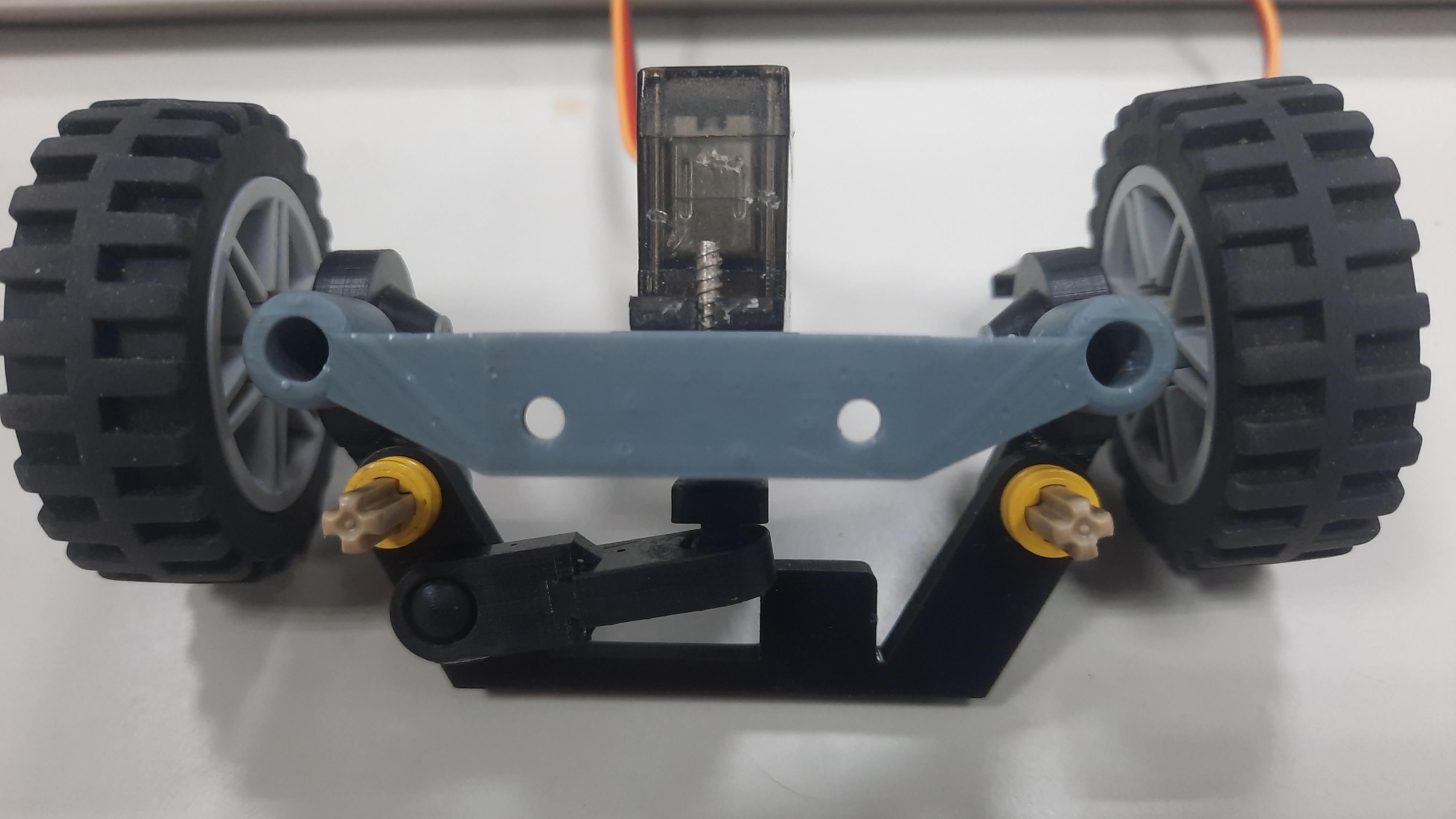 |
Following continuous correction and optimization across the previous generations, the current steering structure fully meets the performance requirements of our vehicle model, achieving a stable design state. |
| LEGO 62821 GearDifferential | LEGO 6573 Gear Differential |
|---|---|
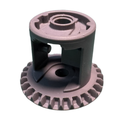 |
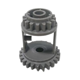 |
| LEGO 62821 Gear Differential | LEGO 6573 Gear Differential |
|---|---|
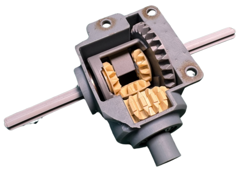 |
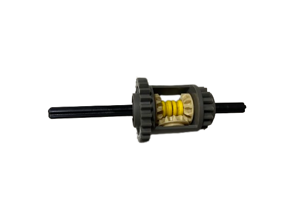 |
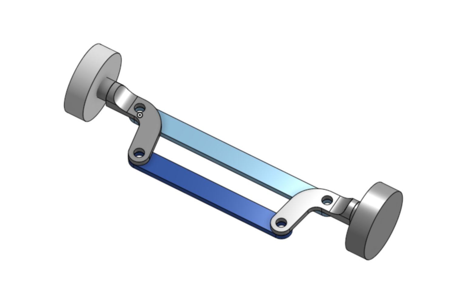 Reference Link:[Ackermann steering geometry@Wikipedia](https://zh.wikipedia.org/zh-tw/%E9%98%BF%E5%85%8B%E6%9B%BC%E8%BD%89%E5%90%91%E5%B9%BE%E4%BD%95)
- #### The principle of Ackermann steering geometry is based on the following concepts:
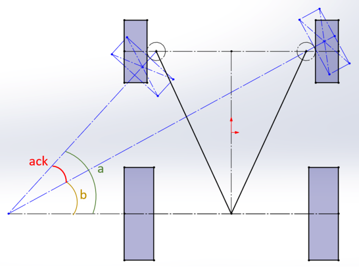
- __Difference in Turning Radius:__ When the vehicle makes a turn, the two front wheels need to rotate at different angles to allow the vehicle to pivot around a central point.
- __Turning Angles of the Two Front Wheels:__ The design of the Ackermann steering geometry ensures that both front wheels pass through a central point simultaneously during steering.
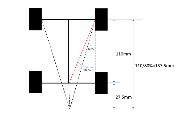
- Compared to the Ackermann steering geometry made from the original 0% LEGO bricks, the steering mechanism of this competition vehicle is designed with reference to an 80% Ackermann steering geometry. It offers advantages such as reduced resistance and smoother turns. The Ackermann steering geometry parts are produced using a stereolithography (SLA) 3D printer. However, the most challenging aspect of the process was adjusting the Ackermann ratio to achieve the ideal turning angle for our vehicle to navigate around blocks effectively.
- #### Why Choose an 80% Ackermann Ratio?
- In theory, this design is the optimal choice for smooth and efficient turns. However, it may lead to excessive tire wear. Therefore, in automobile design, a 100% Ackermann ratio is usually not chosen. Compared to a 100% Ackermann ratio, an 80% Ackermann ratio allows for smoother, more predictable turns, improves maneuverability, and reduces tire wear.
- #### Calculating the Ackermann Angle Graphically (a-b = ack)
 |
 |