# BabyCube Assembly Instructions
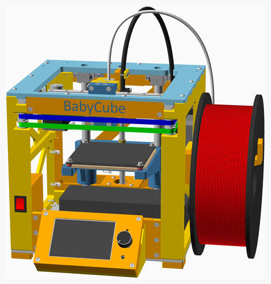
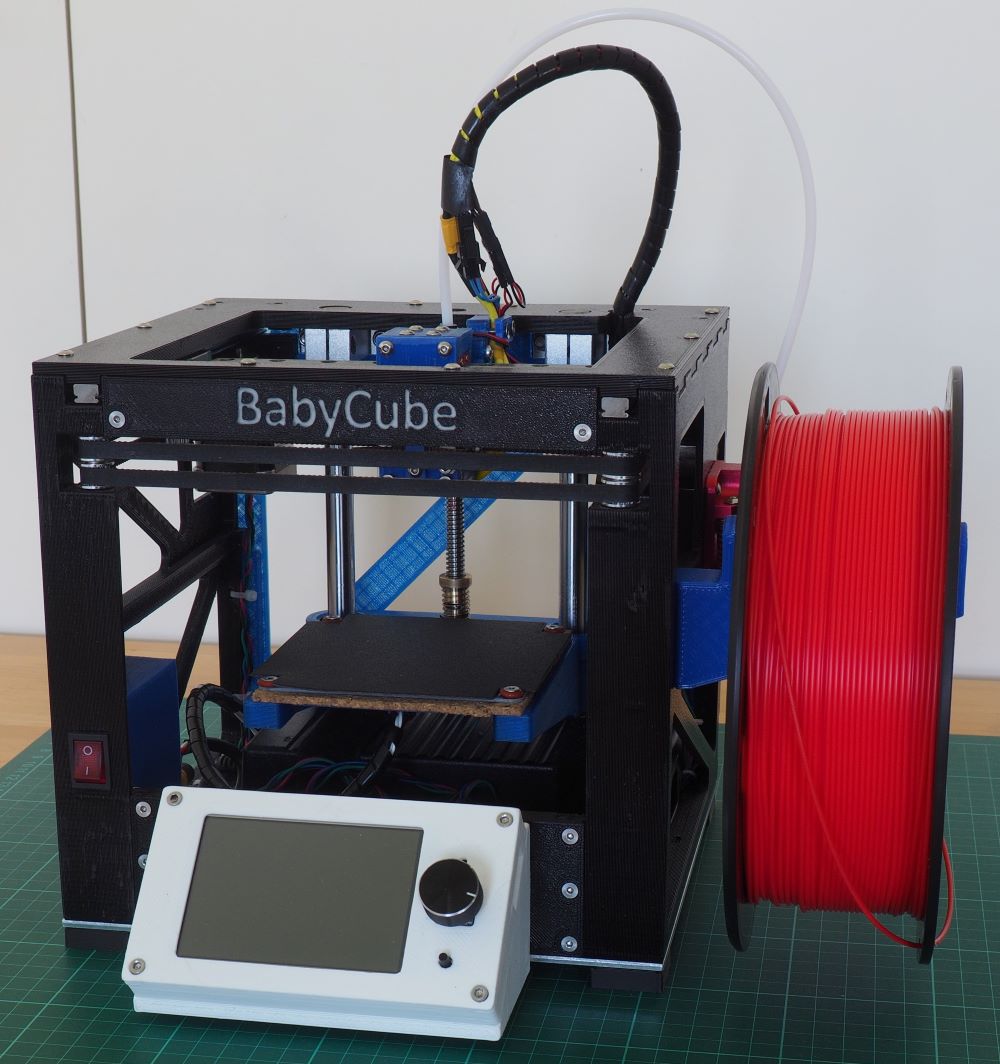
These are the assembly instructions for the BabyCube. These instructions are not fully comprehensive, that is they do
not show every small detail of the construction, and in particular they do not show the wiring. However there is sufficient
detail that someone with a good understanding of 3D printers can build the BabyCube.
---
## Table of Contents
1. [Parts list](#Parts_list)
1. [Printhead_E3DV6_MGN9C_HC assembly](#Printhead_E3DV6_MGN9C_HC_assembly)
1. [X_Carriage_Belt_Side_MGN9C_HC assembly](#X_Carriage_Belt_Side_MGN9C_HC_assembly)
1. [Top_Face_Stage_1 assembly](#Top_Face_Stage_1_assembly)
1. [Top_Face_Stage_2 assembly](#Top_Face_Stage_2_assembly)
1. [Top_Face assembly](#Top_Face_assembly)
1. [Display_Cover assembly](#Display_Cover_assembly)
1. [Display_Housing assembly](#Display_Housing_assembly)
1. [Z_Carriage assembly](#Z_Carriage_assembly)
1. [Print_bed assembly](#Print_bed_assembly)
1. [Back_Face_Stage_1 assembly](#Back_Face_Stage_1_assembly)
1. [Back_Face assembly](#Back_Face_assembly)
1. [Right_Face_Stage_1 assembly](#Right_Face_Stage_1_assembly)
1. [Right_Face assembly](#Right_Face_assembly)
1. [Base assembly](#Base_assembly)
1. [Switch_Shroud assembly](#Switch_Shroud_assembly)
1. [Left_Face assembly](#Left_Face_assembly)
1. [Stage_1 assembly](#Stage_1_assembly)
1. [Stage_2 assembly](#Stage_2_assembly)
1. [Stage_3 assembly](#Stage_3_assembly)
1. [Stage_4 assembly](#Stage_4_assembly)
1. [Stage_5 assembly](#Stage_5_assembly)
1. [Main assembly](#main_assembly)
## Read this before you order parts
The motor for the Z-axis has an integrated lead screw: in the *Parts List* the length specified is the length that
protrudes from the motor. Some suppliers specify the total length of the lead screw, that is including the part that
is inside the motor, so check how your supplier specifies the part before ordering. Another option is to order a motor
with a lead screw that is too long and cut to size, not however that lead screws are made from hardened steel and cannot
be cut with a hacksaw - an angle grinder is required to cut them.
If you wish to use a Raspberry Pi (for running OctoPrint or Klipper), note that there is not enough space for a full size
Raspberry Pi (eg a Pi 4), but the smaller Pi 3A+ or Pi Zero 2W will fit.
## Tips for printing the parts
Many parts on the BabyCube are designed to press-fit together (a bit like Lego), so the tolerances are quite tight.
For this reason it is important you printer is properly calibrated before you print the BabyCube parts. In particular
the extruder should be calibrated, the printbed correctly trammed (levelled), and "elephant's foot" compensation set
if required.
The printed parts can be divided into two classes, the "large parts" (ie the left, right, top and back faces), and the
"small parts" (the rest of the parts)
I recommend using a 0.6mm nozzle for printing all the parts, but especially the for the large parts.
### Parts in proximity to heat sources
A number of parts are in proximity with heat sources, namely the hotend, the heated bed and the motors. Ideally these
should be printed in ABS, but I have used successfully used PETG. These parts are insulated from direct contact with
the heat sources, by O-rings and cork underlay (for the heated bed) and by cork dampers (for the motors). These
insulators should not be omitted from the build.
### Small parts
For dimensional accuracy the small parts need to be printed with a layer height of 0.25mm and a first layer height of 0.25mm.
To maximise part strength, I use the following:
1. extrusion width of 0.7mm if using a 0.6mm nozzle, 0.65mm if using a 0.4mm nozzle
2. 3 perimeters
3. 3 top and bottom layers
4. Grid (or honeycomb) infill - not any of the weaker infills (eg Rectangular). 30% infill.
### Large parts
For the large parts, I use a 0.6mm nozzle with the following settings:
1. Layer height 0.5mm, same for first layer height
2. Extrusion width of 1.0mm
3. 2 perimeters (only 2 needed because of the 1.0mm extrusion width)
4. 2 bottom layers (only 2 needed because of the 0.5mm layer height)
5. 3 top layers (3 needed because the first layer may be in some parts a bridging layer and so is not full strength,
the second and third layers are structural layers).
6. Grid infill at 30%. I find that honeycomb infill, although stronger, is more prone to warping. 30% is used to enable
the part cooling fan to be switched off (see tips below).
7. First layer speed 25mm/s
8. If using a standard E3D v6 hotend (ie not a Volcano or other high-volume hotend) set the max volumetric speed to
14mm3/s for PLA, 11mm3/s for ABS, or 8mm3/s for PETG
The large parts take up almost the full extent of the print bed and as a result can be prone to warping.
If you have problems with warping, I suggest the following:
1. disable the part cooling fan for the first 10mm (20 layers) or more. The part cooling fan is only really required
for the bridges for the motor mounts and switch mounts, since there are no overhangs and the small bolt holes bridge
fine without part cooling.
2. raise the temperature of the heated bed.
3. add a brim
## Part substitutions
There is some scope for part substitution:
1. Generally caphead bolts can be used instead of button head bolts, except on the print head where caphead bolts may interfere
with homing.
2. I strongly recommend using an aluminium baseplate, but if you have difficulty sourcing this, or cutting it to size, a
3D printed baseplate can be used instead.
## Configuring the printer
There are a number of features that are important to consider when configuring the printer.
### Sensorless homing
Configuring sensorless homing on the X and Y axes is done in the standard way. Sensorless homing on the Z-axis must
be set up to home at the bottom of the Z-axis - so that homing does not cause the print head to crash into the print
bed.
### Power management
The steady state power usage of the BabyCube during printing is about 40W, well within the capabilities of the 120W
power supply. However peak power usage must be managed so as not to exceed 120W.
1. Use PID temperature control (not bang-bang) for the heated bed. In Marlin this means defining `PIDTEMPBED` in
`configuration.h`
2. In the printer start gcode in your slicer, do not set all the heating going at once, instead use a phased approach
1. Use `M104 S160` to start the hotend heating without waiting
2. Home the Y axis (note Y axis should be homed before X axis to avoid possible printhead collision with sides)
3. Home the X axis
4. Home the Z axis
5. Use `M400` to wait for the motors to stop
6. Use `M140 S{first_layer_bed_temperature[0]}` to set the first layer bed temperature
7. Use `M109 S{first_layer_temperature[0]}` to set the temperature for nozzle 0 and wait
This avoids having all the motors and both heaters on during startup. Once the hotend and heated bed have warmed up,
their power usage decreases (since they use PID controllers, and power usage is (mostly) proportional (that's the P in
PID) to the difference between the actual heater temperature and the target temperature).
Example printer start gcode for Slic3r/PrusaSlicer/SuperSlicer is [here](../../documents/PrinterStart.gcode).
Example printer end gcode for is [here](../../documents/PrinterEnd.gcode).
### Fans
The power supply is 19.5V and the fans specified are 12V. This is handled by setting `FAN_MAX_PWM` to `157` and
`EXTRUDER_AUTO_FAN_SPEED` to `150` in `configuration_adv.h`. (`12/19.5*255 = 157`, so setting these values to 157 or
less ensures the fans' voltage specification is not exceeded.)
### Marlin configuration
The changes to `configuration.h` and `configuration_adv.h` are [here](../documents/MarlinConfiguration.md).
### Klipper configuration
A starting point for the Klipper configuration is [here](../documents/klipper_btt_skr_mini_e3_v2_0.cfg).
This only a starting point and should be adjusted according to your components.
In particular note that the endstop sensitivities (that is the `driver_SGTHRS` values) must be tuned for each axis.
They are currently set at `255`, the most sensitive value and this will need to be reduced as part of the tuning.
[Top](#TOP)
---
## Parts list
| Printhead E3DV6 MGN9C HC | X Carriage Belt Side MGN9C HC | Top Face | Display Housing | Print Bed | Back Face | Right Face | Base | Left Face | Main | TOTALS | |
|-----:|-----:|-----:|-----:|-----:|-----:|-----:|-----:|-----:|-----:|------:|:-------------|
| | | | | | | | | | | | **Vitamins** |
| . | . | . | . | . | . | . | 1 | . | . | 1 | Aluminium box section 12mm x 8mm x 1mm, length 85mm |
| . | . | . | . | . | . | . | 1 | . | . | 1 | Aluminium sheet 220mm x 204mm x 3mm |
| . | . | . | . | . | . | . | . | . | 1 | 1 | Belt GT2 x 6mm x 742mm |
| . | . | . | . | . | . | . | . | . | 1 | 1 | Belt GT2 x 6mm x 742mm |
| . | . | . | . | . | . | . | 1 | . | . | 1 | BigTreeTech SKR Mini E3 v2.0 |
| . | . | . | 1 | . | . | . | . | . | . | 1 | BigTreeTech TFT35 v3.0 |
| 4 | . | . | . | . | . | . | . | . | . | 4 | Bolt M2 caphead x 6mm |
| . | . | . | . | . | . | . | . | . | 2 | 2 | Bolt M3 buttonhead x 8mm |
| . | . | . | . | . | . | . | 2 | 1 | 4 | 7 | Bolt M3 buttonhead x 10mm |
| 2 | . | . | . | . | 4 | . | . | . | 18 | 24 | Bolt M3 buttonhead x 12mm |
| . | . | . | 4 | . | . | . | . | . | . | 4 | Bolt M3 buttonhead x 16mm |
| . | . | . | 4 | . | . | . | . | . | . | 4 | Bolt M3 caphead x 6mm |
| . | . | 28 | . | 4 | . | . | 10 | . | . | 42 | Bolt M3 caphead x 8mm |
| . | . | 4 | . | . | . | . | . | . | . | 4 | Bolt M3 caphead x 10mm |
| . | . | . | . | . | . | 4 | . | 4 | . | 8 | Bolt M3 caphead x 12mm |
| . | . | 2 | 4 | 4 | . | . | . | . | . | 10 | Bolt M3 caphead x 16mm |
| . | . | 2 | . | . | . | . | . | . | . | 2 | Bolt M3 caphead x 25mm |
| . | 2 | . | . | . | . | . | . | . | . | 2 | Bolt M3 caphead x 30mm |
| . | . | . | . | . | . | . | . | . | 6 | 6 | Bolt M3 countersunk x 6mm |
| . | . | 2 | . | . | . | . | . | . | 14 | 16 | Bolt M3 countersunk x 10mm |
| . | . | . | . | . | . | . | . | 2 | 4 | 6 | Bolt M3 countersunk x 12mm |
| . | . | . | . | . | . | . | . | 2 | . | 2 | Bolt M3 countersunk x 16mm |
| 2 | . | . | . | . | . | . | . | . | . | 2 | Bolt M3 countersunk x 25mm |
| . | . | . | . | . | . | . | . | . | 4 | 4 | Bolt M3 countersunk x 30mm |
| . | . | . | . | . | . | 1 | . | 1 | . | 2 | Bolt M3 countersunk x 35mm |
| . | . | . | . | . | 8 | . | . | . | . | 8 | Bolt M5 countersunk x 16mm |
| . | . | . | . | . | . | 1 | . | 1 | . | 2 | Cork damper NEMA 14 |
| . | . | . | . | . | 1 | 1 | . | . | . | 2 | Cork damper NEMA 17 |
| . | . | . | . | 1 | . | . | . | . | . | 1 | Cork underlay 105mm x 105mm x 3mm |
| 1 | . | . | . | . | . | . | . | . | . | 1 | Fan 30mm x 10mm |
| 1 | . | . | . | . | . | . | . | . | . | 1 | Hot end E3D V6 direct 1.75mm |
| . | . | . | . | 1 | . | . | . | . | . | 1 | Leadscrew nut 8 x 2 |
| . | . | . | . | 2 | . | . | . | . | . | 2 | Linear bearing LM12LUU |
| . | . | 1 | . | . | . | . | . | . | . | 1 | Linear rail MGN9 x 150mm |
| . | . | 2 | . | . | . | . | . | . | . | 2 | Linear rail MGN9 x 200mm |
| . | . | 3 | . | . | . | . | . | . | . | 3 | Linear rail carriage MGN9C |
| . | . | . | . | . | 2 | . | . | . | . | 2 | Linear rod 12mm x 200mm |
| . | . | . | . | . | . | 1 | . | . | . | 1 | MK10 Dual Pulley Extruder |
| . | . | . | . | 1 | . | . | . | . | . | 1 | Magnetic base 100mm x 100mm |
| . | . | . | . | . | 8 | . | . | . | . | 8 | Nut M5 x 4mm nyloc |
| . | . | . | . | 8 | . | . | . | . | . | 8 | O-ring nitrile 4mm x 2mm |
| . | . | . | . | 1 | . | . | . | . | . | 1 | OpenBuilds mini heated bed 100mm x 100mm |
| . | . | . | . | . | . | . | . | . | 1 | 1 | PTFE tube 295 mm |
| . | . | . | . | . | . | . | 5 | . | . | 5 | Pillar hex nylon F/F M3x12 |
| . | . | . | . | 1 | . | . | . | . | . | 1 | Print surface 100mm x 100mm |
| . | . | 2 | . | . | . | 2 | . | 2 | . | 6 | Pulley GT2 idler 16 teeth |
| . | . | 2 | . | . | . | . | . | . | . | 2 | Pulley GT2 idler smooth 9.63mm |
| . | . | . | . | . | . | 1 | . | 1 | . | 2 | Pulley GT2UM 20 teeth |
| . | . | . | . | . | . | . | 1 | . | . | 1 | Raspberry Pi 3A+ (optional) |
| . | . | . | . | . | . | . | . | 1 | . | 1 | Rocker Switch PRASA1-16F-BB0BW |
| . | . | . | . | . | 4 | . | . | . | . | 4 | SK12 shaft support bracket |
| . | . | . | . | . | . | . | . | . | 1 | 1 | Spiral wrap, 500mm |
| 1 | . | . | . | . | . | . | . | . | . | 1 | Square radial fan 3010 |
| . | . | . | . | . | . | 1 | . | 1 | . | 2 | Stepper motor NEMA14 x 36mm |
| . | . | . | . | . | 1 | . | . | . | . | 1 | Stepper motor NEMA17 x 34mm, 150mm integrated leadscrew |
| . | . | . | . | . | . | 1 | . | . | . | 1 | Stepper motor NEMA17 x 40mm |
| . | . | . | . | . | 1 | . | . | . | . | 1 | Stepper motor cable, 150mm |
| . | . | . | . | . | . | 2 | . | 1 | . | 3 | Stepper motor cable, 400mm |
| . | 2 | 6 | . | 8 | . | 6 | . | 6 | . | 28 | Washer M3 x 7mm x 0.5mm |
| . | . | . | . | . | . | . | . | 2 | . | 2 | Wire black 12SWG, length 100mm |
| . | . | . | . | . | . | . | . | 2 | . | 2 | Wire red 12SWG, length 100mm |
| . | . | . | . | . | . | . | . | 1 | . | 1 | XT60 Connector Female |
| . | . | . | . | . | . | . | . | 1 | . | 1 | XT60 Connector Female - not shown |
| . | . | . | . | . | . | . | . | 1 | . | 1 | XT60 Connector Male |
| . | . | . | . | . | . | . | . | 1 | . | 1 | XT60 Connector Male - not shown |
| 1 | . | . | . | 2 | . | 5 | . | 4 | 4 | 16 | Ziptie 2.5mm x 100mm min length |
| 12 | 4 | 54 | 13 | 33 | 29 | 26 | 21 | 35 | 60 | 287 | Total vitamins count |
| | | | | | | | | | | | **3D printed parts** |
| . | . | . | . | . | 1 | . | . | . | . | 1 | Back_Face.stl |
| . | . | . | . | . | . | . | 1 | . | . | 1 | Base.stl |
| . | . | . | . | . | . | . | 1 | . | . | 1 | Base_Template.stl |
| . | . | . | 1 | . | . | . | . | . | . | 1 | Display_Housing.stl |
| . | . | . | 1 | . | . | . | . | . | . | 1 | Display_Housing_Bracket.stl |
| 1 | . | . | . | . | . | . | . | . | . | 1 | E3DV6_Clamp.stl |
| 1 | . | . | . | . | . | . | . | . | . | 1 | Fan_Duct.stl |
| . | . | . | . | . | . | . | . | . | 4 | 4 | Foot_LShaped_8mm.stl |
| . | . | . | 1 | . | . | . | . | . | . | 1 | Front_Lower_Chord.stl |
| . | . | . | . | . | . | . | . | . | 1 | 1 | Front_Upper_Chord.stl |
| 1 | . | . | . | . | . | . | . | . | . | 1 | Hotend_Strain_Relief_Clamp.stl |
| . | . | . | . | . | . | . | . | 1 | . | 1 | Left_Face.stl |
| . | . | . | . | . | . | . | 1 | . | . | 1 | PSU_Bracket.stl |
| . | . | . | . | . | . | . | 2 | . | . | 2 | PSU_Support.stl |
| . | . | . | . | . | . | 1 | . | . | . | 1 | Right_Face.stl |
| . | . | . | . | . | . | . | . | . | 1 | 1 | Spool_Holder.stl |
| . | . | . | . | . | . | . | . | 1 | . | 1 | Switch_Shroud.stl |
| . | . | . | . | . | . | . | . | 1 | . | 1 | Switch_Shroud_Clamp.stl |
| . | . | 1 | . | . | . | . | . | . | . | 1 | Top_Face.stl |
| . | . | . | . | . | . | . | . | . | 1 | 1 | X_Carriage_Belt_Clamp.stl |
| . | 1 | . | . | . | . | . | . | . | . | 1 | X_Carriage_Belt_Side_MGN9C_HC.stl |
| . | 2 | . | . | . | . | . | . | . | . | 2 | X_Carriage_Belt_Tensioner.stl |
| 1 | . | . | . | . | . | . | . | . | . | 1 | X_Carriage_Groovemount_MGN9C_HC.stl |
| . | . | 1 | . | . | . | . | . | . | . | 1 | Y_Carriage_Brace_Left.stl |
| . | . | 1 | . | . | . | . | . | . | . | 1 | Y_Carriage_Brace_Right.stl |
| . | . | 1 | . | . | . | . | . | . | . | 1 | Y_Carriage_Left.stl |
| . | . | 1 | . | . | . | . | . | . | . | 1 | Y_Carriage_Right.stl |
| . | . | . | . | 1 | . | . | . | . | . | 1 | Z_Carriage.stl |
| 4 | 3 | 5 | 3 | 1 | 1 | 1 | 5 | 3 | 7 | 33 | Total 3D printed parts count |
| | | | | | | | | | | | **CNC routed parts** |
| . | . | . | . | . | . | . | 1 | . | . | 1 | BaseAL.dxf |
| . | . | . | . | . | . | . | 1 | . | . | 1 | Total CNC routed parts count |
[Top](#TOP)
---
## Printhead_E3DV6_MGN9C_HC assembly
### Vitamins
| Qty | Description |
|----:|:------------|
| 4 | Bolt M2 caphead x 6mm |
| 2 | Bolt M3 buttonhead x 12mm |
| 2 | Bolt M3 countersunk x 25mm |
| 1 | Fan 30mm x 10mm |
| 1 | Hot end E3D V6 direct 1.75mm |
| 1 | Square radial fan 3010 |
| 1 | Ziptie 2.5mm x 100mm min length |
### 3D Printed parts
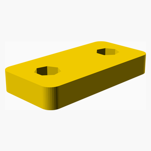
| 1 x E3DV6_Clamp.stl | 1 x Fan_Duct.stl | 1 x Hotend_Strain_Relief_Clamp.stl |
|----------|----------|----------|
|  |  |  |
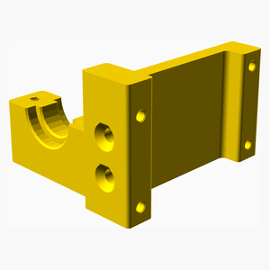
| 1 x X_Carriage_Groovemount_MGN9C_HC.stl |
|----------|
|  |
### Assembly instructions
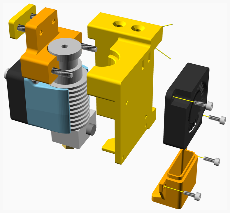
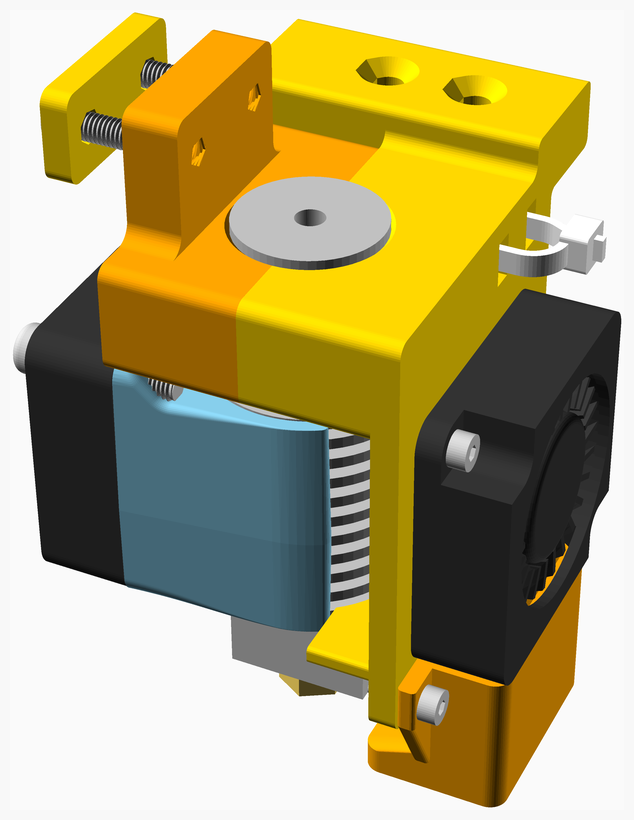
1. Assemble the E3D hotend, including fan, thermistor cartridge and heater cartridge.
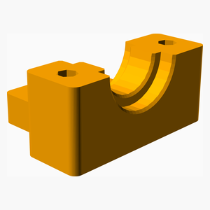
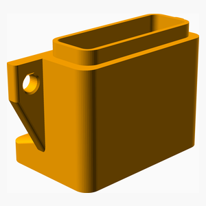
2. Use the **E3DV6_Clamp** to attach the hotend to the **X_Carriage_Groovemount**.
3. Collect the wires together and attach to the **X_Carriage_Groovemount** using the **Hotend_Strain_Relief_Clamp**.
[Top](#TOP)
---
## X_Carriage_Belt_Side_MGN9C_HC assembly
### Vitamins
| Qty | Description |
|----:|:------------|
| 2 | Bolt M3 caphead x 30mm |
| 2 | Washer M3 x 7mm x 0.5mm |
### 3D Printed parts
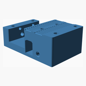
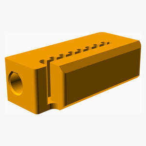
| 1 x X_Carriage_Belt_Side_MGN9C_HC.stl | 2 x X_Carriage_Belt_Tensioner.stl |
|----------|----------|
|  |  |
### Assembly instructions
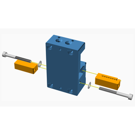
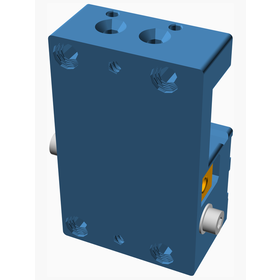
Insert the belts into the **X_Carriage_Belt_Tensioner**s and then bolt the tensioners into the
**X_Carriage_Belt_Side_MGN9C** part as shown. Note the belts are not shown in this diagram.
[Top](#TOP)
---
## Top_Face_Stage_1 assembly
### Vitamins
| Qty | Description |
|----:|:------------|
| 18 | Bolt M3 caphead x 8mm |
| 2 | Bolt M3 countersunk x 10mm |
| 2 | Linear rail MGN9 x 200mm |
| 2 | Linear rail carriage MGN9C |
### 3D Printed parts
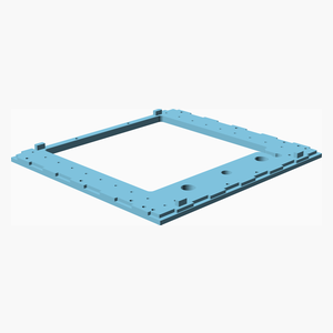
| 1 x Top_Face.stl |
|----------|
|  |
### Assembly instructions
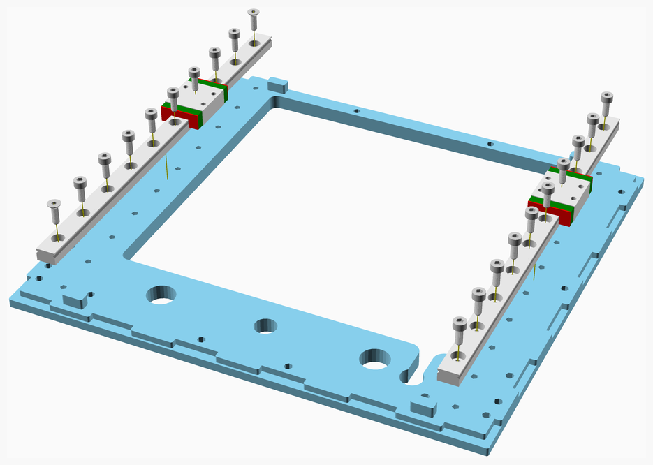
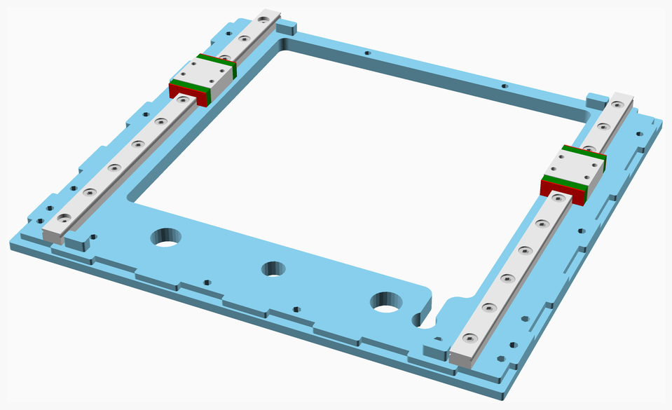
1. Turn the **Top_Face** upside down and place it on a flat surface.
2. Bolt the rails to the **Top_Face**. Note that the first and last bolts on the left rail are countersunk bolts and act
as pilot bolts to ensure the rails are aligned precisely - they should be tightened before all the other bolts on the
left side.
3. The bolts on the right side rail should be only loosely tightened - they will be fully tightened when the right rail
is aligned when the X axis rail is added.
[Top](#TOP)
---
## Top_Face_Stage_2 assembly
### Vitamins
| Qty | Description |
|----:|:------------|
| 10 | Bolt M3 caphead x 8mm |
| 2 | Bolt M3 caphead x 16mm |
| 2 | Bolt M3 caphead x 25mm |
| 2 | Pulley GT2 idler 16 teeth |
| 2 | Pulley GT2 idler smooth 9.63mm |
| 6 | Washer M3 x 7mm x 0.5mm |
### 3D Printed parts
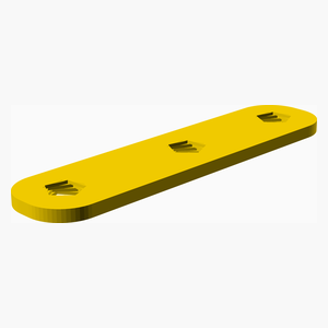
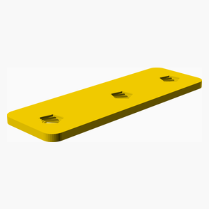
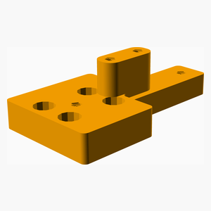
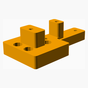
| 1 x Y_Carriage_Brace_Left.stl | 1 x Y_Carriage_Brace_Right.stl | 1 x Y_Carriage_Left.stl |
|----------|----------|----------|
|  |  |  |
| 1 x Y_Carriage_Right.stl |
|----------|
|  |
### Sub-assemblies
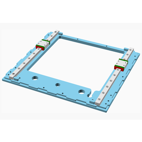
| 1 x Top_Face_Stage_1_assembly |
|----------|
|  |
### Assembly instructions
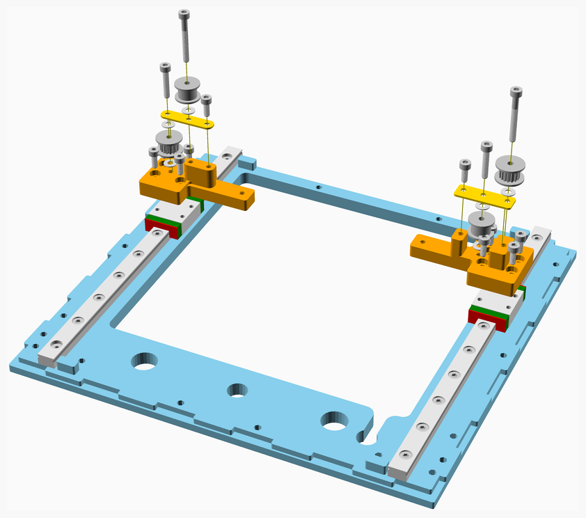
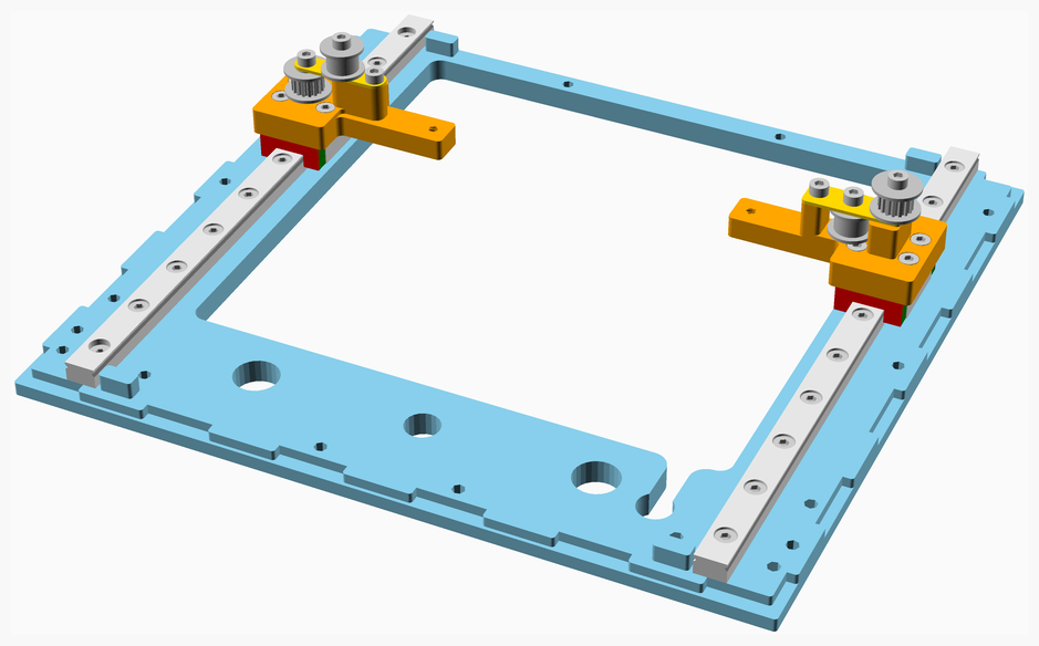
Attach the left and right **Y_carriages** to the top face rails. Note that the two carriages are not interchangeable
so be sure to attach them as shown in the diagram.
The carriages should be attached to the rails before the pulleys are added, since otherwise the bolts are not
accessible.
Attach the pulleys to the carriages. Note that the toothless pulleys are on the inside. Note also that there is a
washer under each of the upper pulleys, but not on top of those pulleys.
Tighten the pulley bolts until the pulleys stop running freely, and then loosen them slightly (approximately 1/16
of a turn) so they run freely.
[Top](#TOP)
---
## Top_Face assembly
### Vitamins
| Qty | Description |
|----:|:------------|
| 4 | Bolt M3 caphead x 10mm |
| 1 | Linear rail MGN9 x 150mm |
| 1 | Linear rail carriage MGN9C |
### Sub-assemblies
| 1 x Top_Face_Stage_2_assembly |
|----------|
|  |
### Assembly instructions
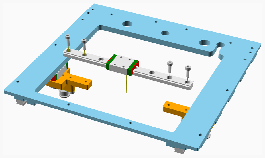
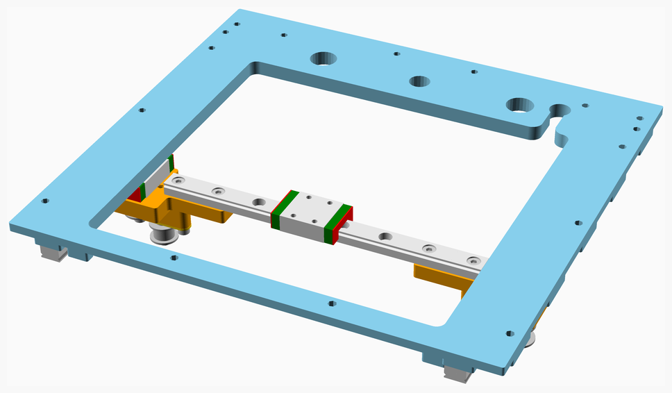
1. Turn the **Top_Face** into its normal orientation.
2. Bolt the X-axis linear rail onto the Y carriages.
3. Turn the Top_Face upside down again and place it on a flat surface.
4. Align the left and right Y-axis linear rails. Do this by pushing the X-axis rail to the rear of the **Top_Face** and tighten
the corresponding bolts (left loose in a previous step) and then push the X-axis rails to the front of the **Top_Face**,
again tightening the corresponding bolts.
5. Check that the carriages run smoothly on the Y-axis linear rails.
[Top](#TOP)
---
## Display_Cover assembly
### Vitamins
| Qty | Description |
|----:|:------------|
| 1 | BigTreeTech TFT35 v3.0 |
| 4 | Bolt M3 caphead x 6mm |
### 3D Printed parts
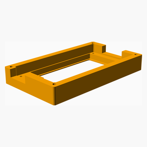
| 1 x Display_Housing.stl |
|----------|
|  |
### Assembly instructions
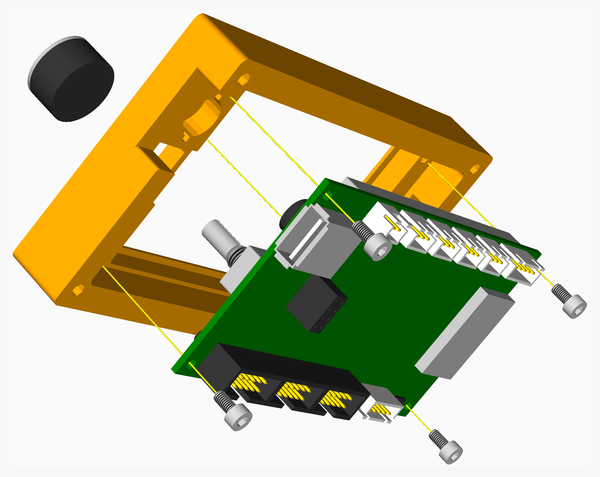
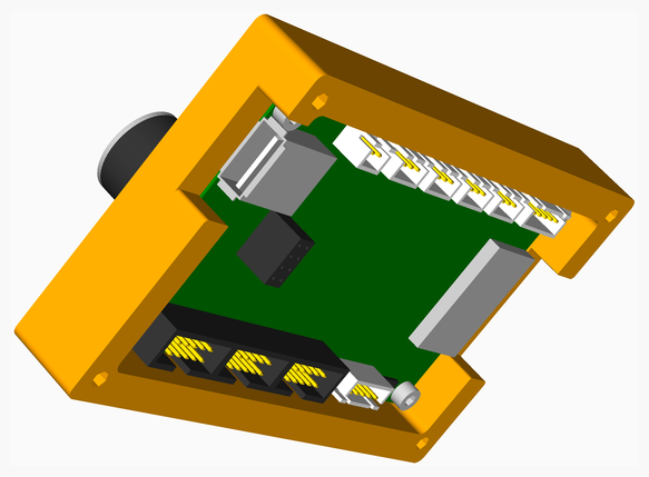
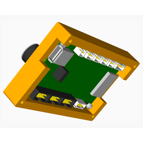
Place the display into the housing and secure it with the bolts - use the bolts to self-tap the holes in the housing.
Attach the knob to the display.
[Top](#TOP)
---
## Display_Housing assembly
### Vitamins
| Qty | Description |
|----:|:------------|
| 4 | Bolt M3 buttonhead x 16mm |
| 4 | Bolt M3 caphead x 16mm |
### 3D Printed parts
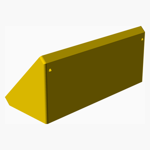
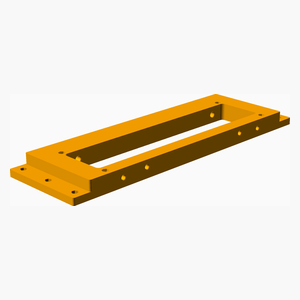
| 1 x Display_Housing_Bracket.stl | 1 x Front_Lower_Chord.stl |
|----------|----------|
|  |  |
### Sub-assemblies
| 1 x Display_Cover_assembly |
|----------|
|  |
### Assembly instructions
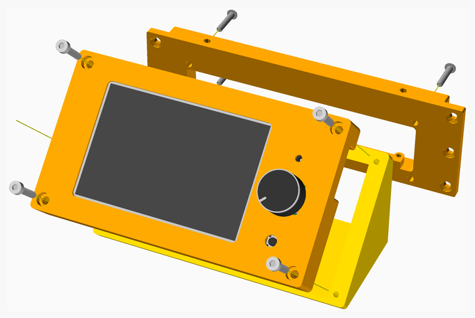
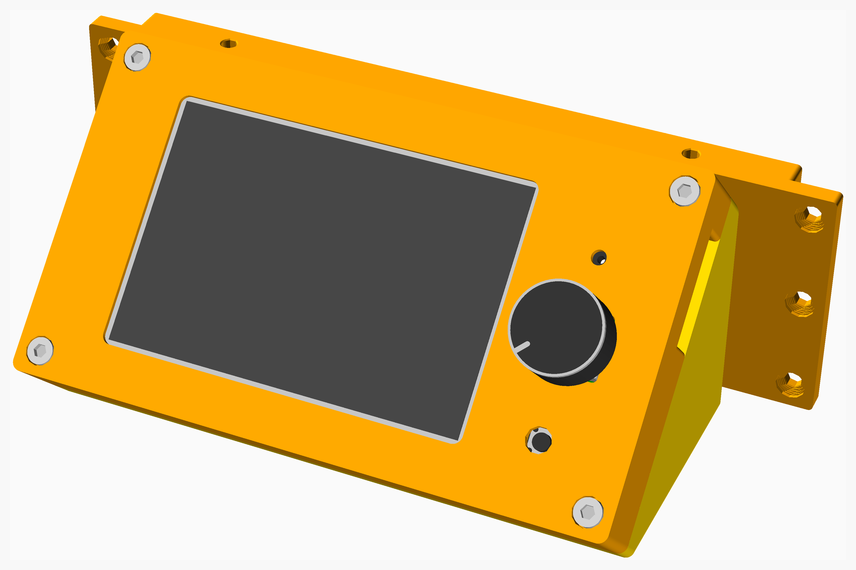
1. Bolt the **Display_Cover_assembly** to the **Display_Housing_Bracket**.
2. Bolt the **Display_Housing_Bracket** to **the Front_Lower_Chord**.
[Top](#TOP)
---
## Z_Carriage assembly
### Vitamins
| Qty | Description |
|----:|:------------|
| 4 | Bolt M3 caphead x 8mm |
| 1 | Leadscrew nut 8 x 2 |
| 2 | Linear bearing LM12LUU |
### 3D Printed parts
| 1 x Z_Carriage.stl |
|----------|
|  |
### Assembly instructions
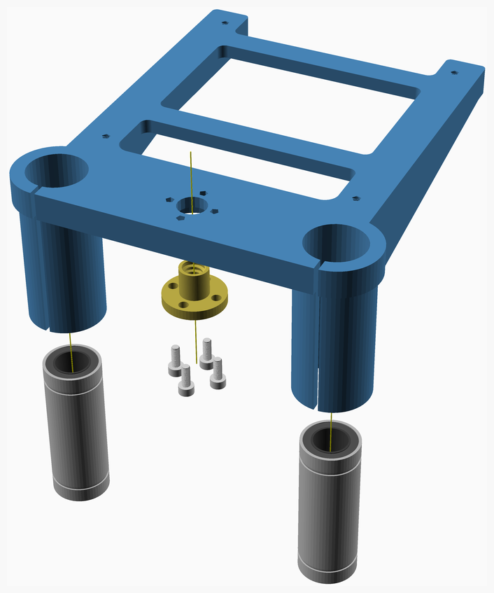
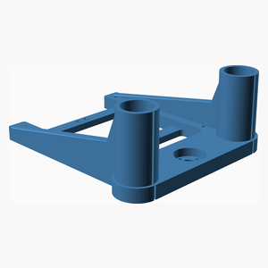
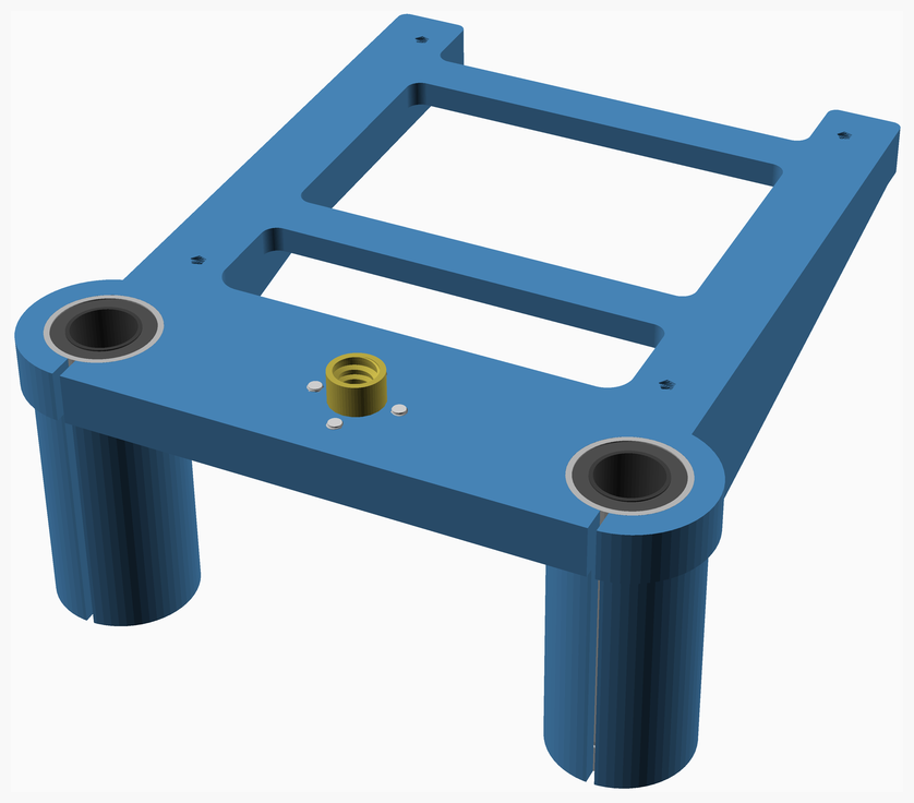
Slide the linear bearings into the **Z_Carriage**.
Affix the leadscrew nut.
[Top](#TOP)
---
## Print_bed assembly
### Vitamins
| Qty | Description |
|----:|:------------|
| 4 | Bolt M3 caphead x 16mm |
| 1 | Cork underlay 105mm x 105mm x 3mm |
| 1 | Magnetic base 100mm x 100mm |
| 8 | O-ring nitrile 4mm x 2mm |
| 1 | OpenBuilds mini heated bed 100mm x 100mm |
| 1 | Print surface 100mm x 100mm |
| 8 | Washer M3 x 7mm x 0.5mm |
| 2 | Ziptie 2.5mm x 100mm min length |
### Sub-assemblies
| 1 x Z_Carriage_assembly |
|----------|
| 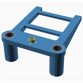 |
### Assembly instructions
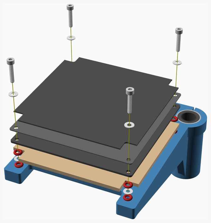
This is the standard variant of the print bed, using an OpenBuilds 100mm heated bed. There is also a version using
a 120 x 120 x 6 mm aluminium tooling plate, see [printbed 120](../../PRINTBED120/readme.md).
1. Prepare the the cork underlay by cutting it to size, making a cutout for the heated bed wiring, and making cutouts
for the bolts and O-rings.
2. Prepare the magnetic base by drilling holes for the bolts.
3. Prepare the heated bed by soldering on the wires and sticking on the magnetic base. Drill bolt holes in the magnetic base.
4. Place the cork underlay on the **Z_Carriage** and place the heated bed on top.
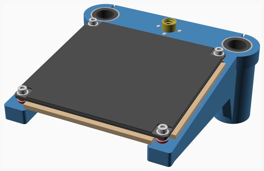
5. Secure the heated bed to the **Z_Carriage**, using the bolts and O-rings. The O-rings allow for bed leveling and help
thermally insulate the heated bed from the **Z_Carriage**.
6. Secure the heated bed wiring to the underside of the printbed using zipties.
[Top](#TOP)
---
## Back_Face_Stage_1 assembly
### Vitamins
| Qty | Description |
|----:|:------------|
| 8 | Bolt M5 countersunk x 16mm |
| 8 | Nut M5 x 4mm nyloc |
| 4 | SK12 shaft support bracket |
### 3D Printed parts
| 1 x Back_Face.stl |
|----------|
|  |
### Assembly instructions
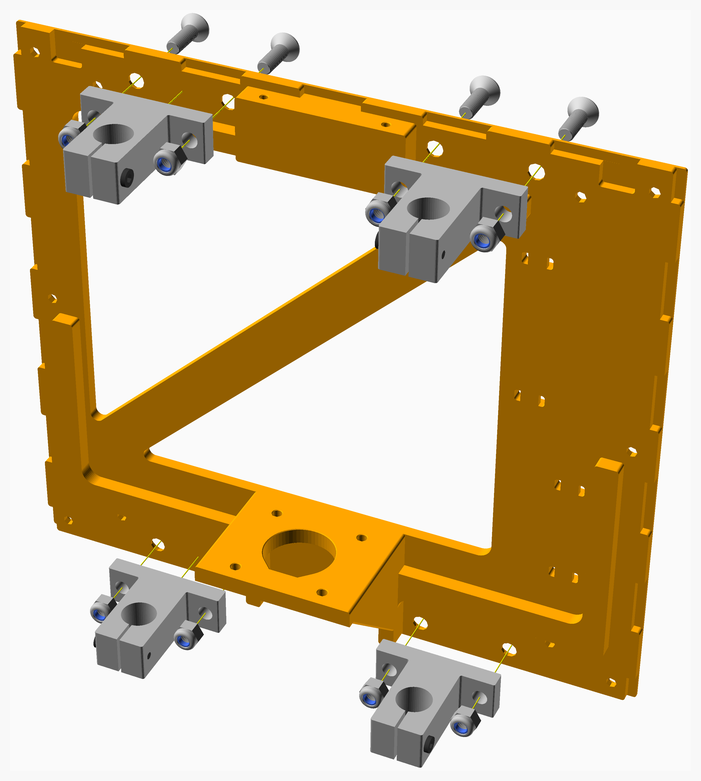
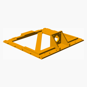
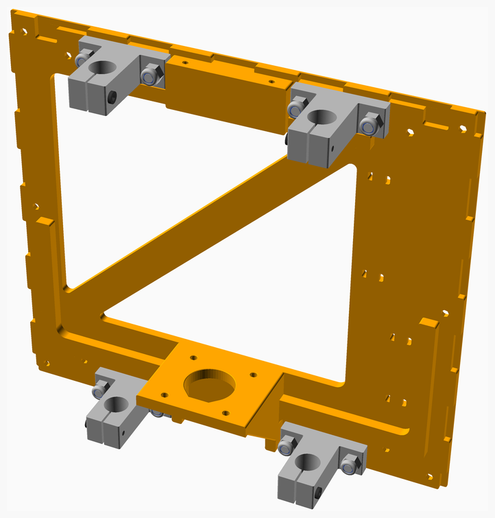
Attach the SK brackets to the **Back_Face**. Note the orientation of the tightening bolts: the top tightening bolts should
face inward and the bottom tightening bolts should face outward. This allows access after the BabyCube is fully assembled.
[Top](#TOP)
---
## Back_Face assembly
### Vitamins
| Qty | Description |
|----:|:------------|
| 4 | Bolt M3 buttonhead x 12mm |
| 1 | Cork damper NEMA 17 |
| 2 | Linear rod 12mm x 200mm |
| 1 | Stepper motor NEMA17 x 34mm, 150mm integrated leadscrew |
| 1 | Stepper motor cable, 150mm |
### Sub-assemblies
| 1 x Back_Face_Stage_1_assembly | 1 x Print_bed_assembly |
|----------|----------|
|  |  |
### Assembly instructions
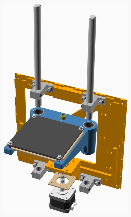
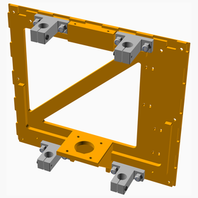
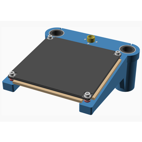
1. Slide the linear rods through the SK brackets and the printbed bearings.
2. Tighten the bolts in the SK brackets, ensuring the **Z_Carriage** slides freely on the rods.
3. Place the cork damper on the stepper motor and thread the lead screw through the leadnut and attach the stepper motor
to the **Back_Face**. Note the orientation of the JST socket.
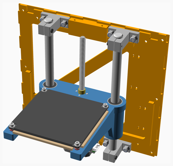
[Top](#TOP)
---
## Right_Face_Stage_1 assembly
### Vitamins
| Qty | Description |
|----:|:------------|
| 4 | Bolt M3 caphead x 12mm |
| 1 | Bolt M3 countersunk x 35mm |
| 1 | Cork damper NEMA 14 |
| 2 | Pulley GT2 idler 16 teeth |
| 1 | Pulley GT2UM 20 teeth |
| 1 | Stepper motor NEMA14 x 36mm |
| 1 | Stepper motor cable, 400mm |
| 6 | Washer M3 x 7mm x 0.5mm |
| 3 | Ziptie 2.5mm x 100mm min length |
### 3D Printed parts
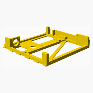
| 1 x Right_Face.stl |
|----------|
|  |
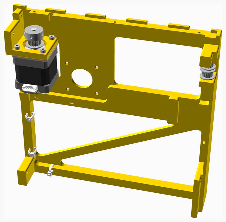
### Assembly instructions
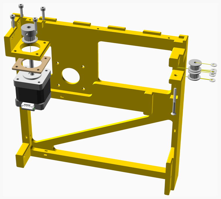
1. Place the cork damper on the stepper motor and bolt the motor to the frame.
Note the cork damper is important as it provides thermal insulation between the stepper motor and the frame.
Note orientation of the JST connector.
2. Attach the toothed idler pulleys to the frame, separated by the washers as shown.
3. Thread the zip ties through the frame, but do not tighten them yet, since the extruder motor cable will also go through
the zip ties.
[Top](#TOP)
---
## Right_Face assembly
### Vitamins
| Qty | Description |
|----:|:------------|
| 1 | Cork damper NEMA 17 |
| 1 | MK10 Dual Pulley Extruder |
| 1 | Stepper motor NEMA17 x 40mm |
| 1 | Stepper motor cable, 400mm |
| 2 | Ziptie 2.5mm x 100mm min length |
### Sub-assemblies
| 1 x Right_Face_Stage_1_assembly |
|----------|
|  |
### Assembly instructions
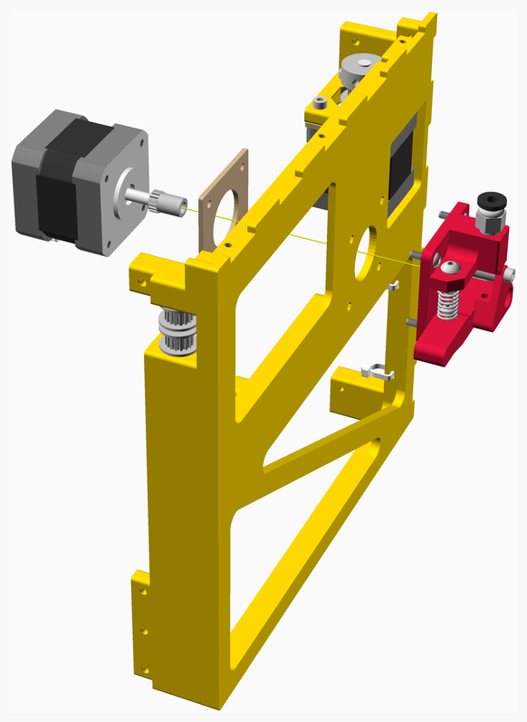
1. Attach the extruder gear to the stepper motor.
2. Place the cork damper on the stepper motor and attach the motor through the frame to the extruder. Note the cork
damper is important as it provides thermal insulation between the stepper motor and the frame.
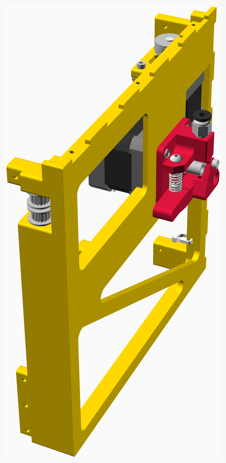
3. Secure the cables for both motors with the zip ties.
[Top](#TOP)
---
## Base assembly
### Vitamins
| Qty | Description |
|----:|:------------|
| 1 | Aluminium box section 12mm x 8mm x 1mm, length 85mm |
| 1 | Aluminium sheet 220mm x 204mm x 3mm |
| 1 | BigTreeTech SKR Mini E3 v2.0 |
| 2 | Bolt M3 buttonhead x 10mm |
| 10 | Bolt M3 caphead x 8mm |
| 5 | Pillar hex nylon F/F M3x12 |
| 1 | Raspberry Pi 3A+ (optional) |
### 3D Printed parts
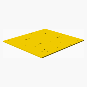
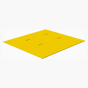
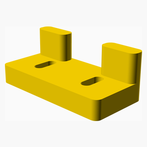
| 1 x Base.stl | 1 x Base_Template.stl | 1 x PSU_Bracket.stl |
|----------|----------|----------|
|  |  |  |
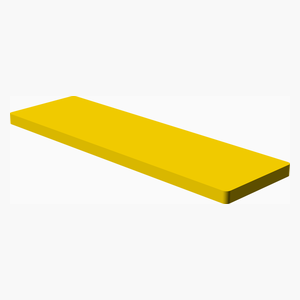
| 2 x PSU_Support.stl |
|----------|
|  |
### CNC Routed parts
| 1 x BaseAL.dxf |
|----------|
| 
### Assembly instructions
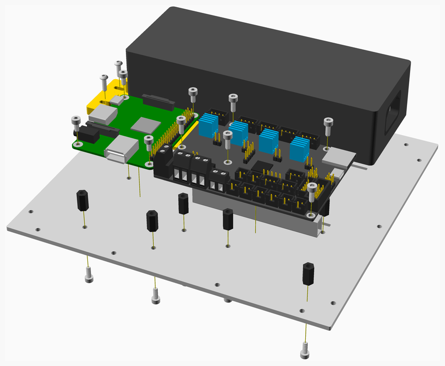
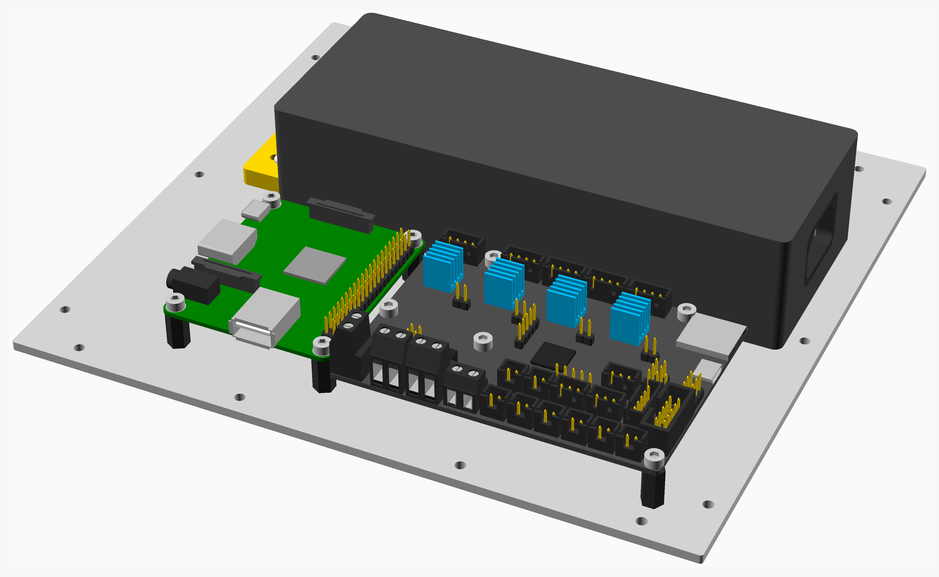
1. Attach the Base_Template to the aluminium sheet and use it to drill out the holes. The base template has 2mm holes
marked out for pilot holes. Once you have drilled these re-drill the holes with a 3mm bit. Note that the Base_Template
has holes marked for the BTT E3 Mini V2, the BTT E3 Turbo and the BTT STL 1.4 boards - choose the appropriate holes for
your board. If you are unable to source an aluminium sheet, it is possible to print and use the Base.stl file, but
using and aluminium plate is much preferred.
2. Attach the PSU_Supports to the base plate with double sided tape.
3. Bolt the PSU_Bracket to the base plate.
4. Attach the PSU to the base plate with the velcro straps.
5. Cover the top and bottom sides of the box section with thermal paste.
6. Attach the box section to the bottom of the control board with electrical tape. The tape serves to keep the box
section in place until it is attached to the base plate.
7. Using the hex pillars, attach the control board to the base plate.
[Top](#TOP)
---
## Switch_Shroud assembly
### Vitamins
| Qty | Description |
|----:|:------------|
| 1 | Bolt M3 buttonhead x 10mm |
| 2 | Wire black 12SWG, length 100mm |
| 2 | Wire red 12SWG, length 100mm |
| 1 | XT60 Connector Female |
| 1 | XT60 Connector Female - not shown |
| 1 | XT60 Connector Male |
| 1 | XT60 Connector Male - not shown |
### 3D Printed parts
| 1 x Switch_Shroud.stl | 1 x Switch_Shroud_Clamp.stl |
|----------|----------|
|  |  |
### Assembly instructions
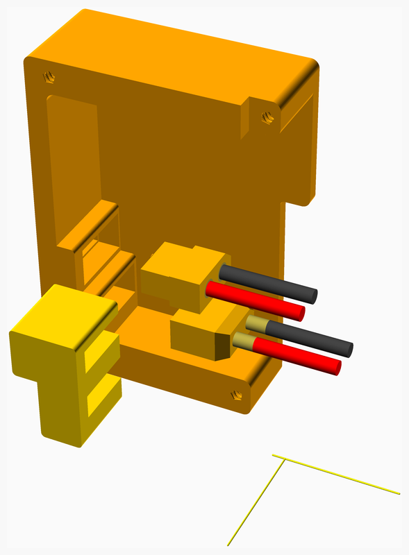
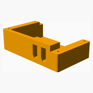
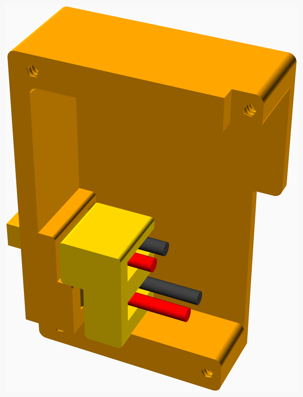
Place the XT60 connectors through the **Switch_Shroud** and bolt on the **Switch_Shroud_Clamp** to keep them in place.
[Top](#TOP)
---
## Left_Face assembly
### Vitamins
| Qty | Description |
|----:|:------------|
| 4 | Bolt M3 caphead x 12mm |
| 2 | Bolt M3 countersunk x 12mm |
| 2 | Bolt M3 countersunk x 16mm |
| 1 | Bolt M3 countersunk x 35mm |
| 1 | Cork damper NEMA 14 |
| 2 | Pulley GT2 idler 16 teeth |
| 1 | Pulley GT2UM 20 teeth |
| 1 | Rocker Switch PRASA1-16F-BB0BW |
| 1 | Stepper motor NEMA14 x 36mm |
| 1 | Stepper motor cable, 400mm |
| 6 | Washer M3 x 7mm x 0.5mm |
| 4 | Ziptie 2.5mm x 100mm min length |
### 3D Printed parts
| 1 x Left_Face.stl |
|----------|
|  |
### Sub-assemblies
| 1 x Switch_Shroud_assembly |
|----------|
|  |
### Assembly instructions
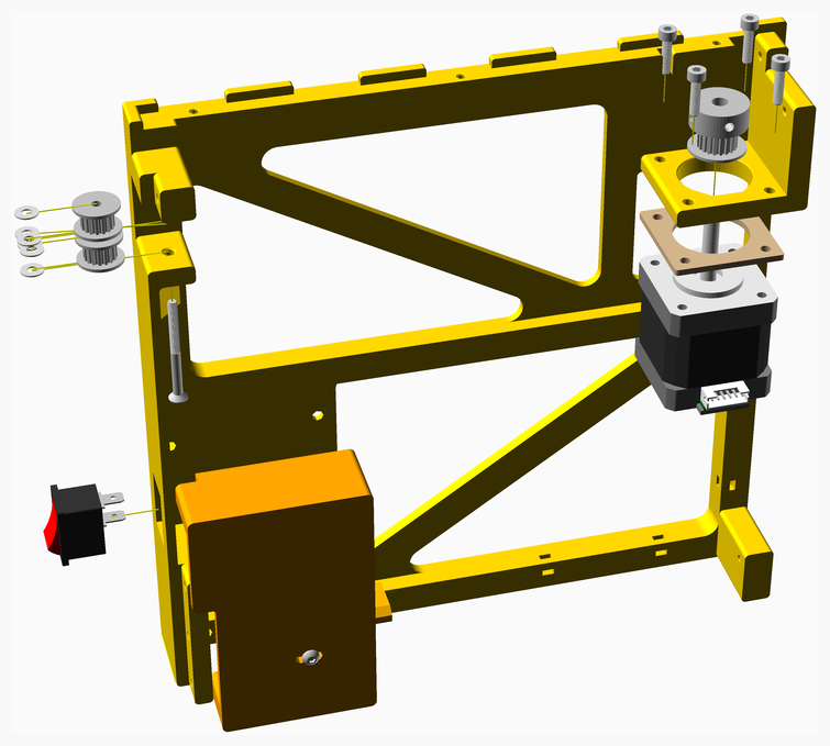
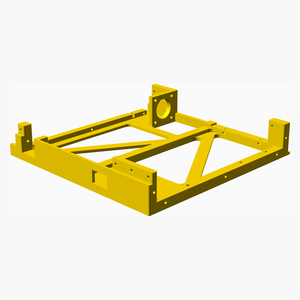
1. Place the cork damper on the stepper motor and bolt the motor to the frame.
Note the cork damper is important as it provides thermal insulation between the stepper motor and the frame.
Note orientation of the JST connector.
2. Secure the motor wires with zip ties.
3. Bolt the two front idler pulleys with washers to the frame.
4. Attach the wires to the switch and bolt the **Switch_Shroud** to the left face.
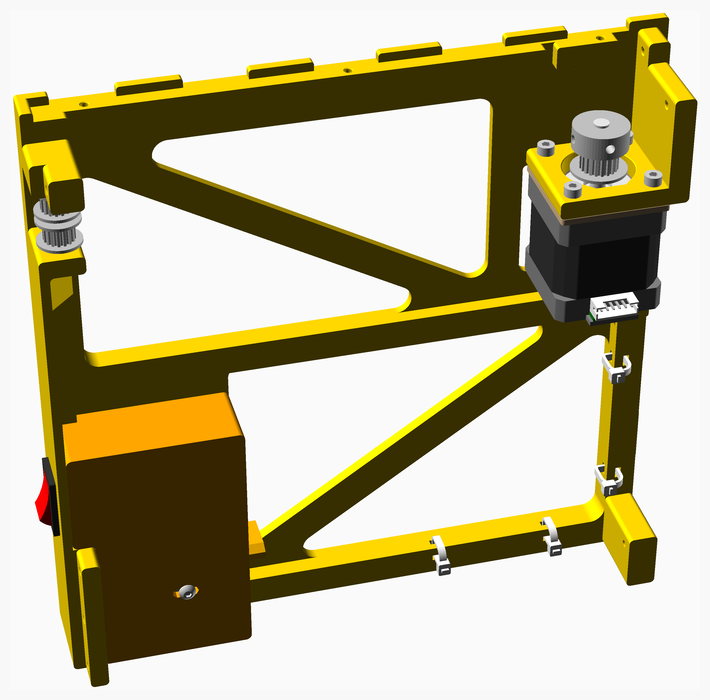
[Top](#TOP)
---
## Stage_1 assembly
### Vitamins
| Qty | Description |
|----:|:------------|
| 2 | Bolt M3 buttonhead x 8mm |
| 8 | Bolt M3 buttonhead x 12mm |
### 3D Printed parts
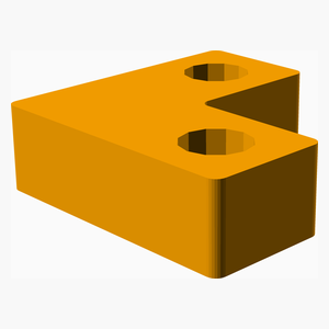
| 4 x Foot_LShaped_8mm.stl |
|----------|
|  |
### Sub-assemblies
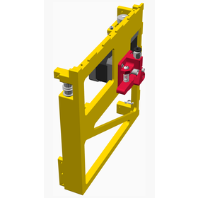
| 1 x Base_assembly | 1 x Left_Face_assembly | 1 x Right_Face_assembly |
|----------|----------|----------|
|  |  |  |
### Assembly instructions
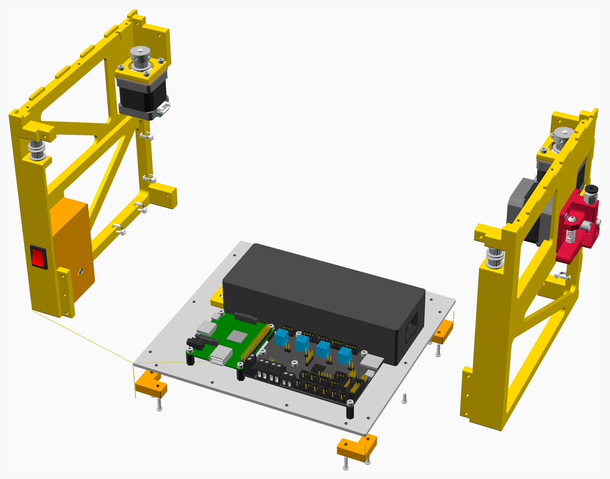
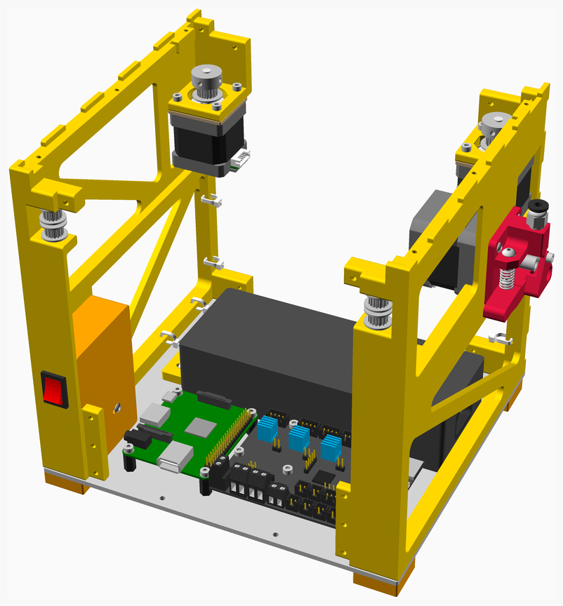
1. Bolt the **Left_Face** and the left feet to the base.
2. Bolt the **Right_Face** and the right feet to the base.
[Top](#TOP)
---
## Stage_2 assembly
### Vitamins
| Qty | Description |
|----:|:------------|
| 2 | Bolt M3 buttonhead x 10mm |
| 6 | Bolt M3 countersunk x 6mm |
| 4 | Bolt M3 countersunk x 10mm |
| 4 | Ziptie 2.5mm x 100mm min length |
### Sub-assemblies
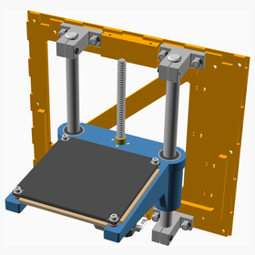
| 1 x Back_Face_assembly | 1 x Stage_1_assembly |
|----------|----------|
|  |  |
### Assembly instructions
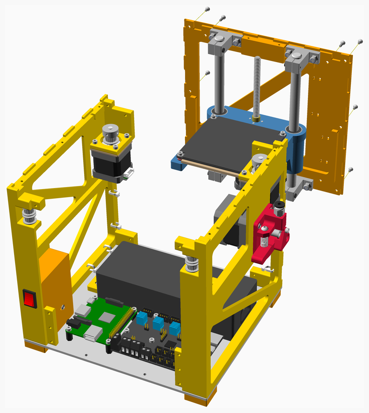
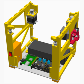
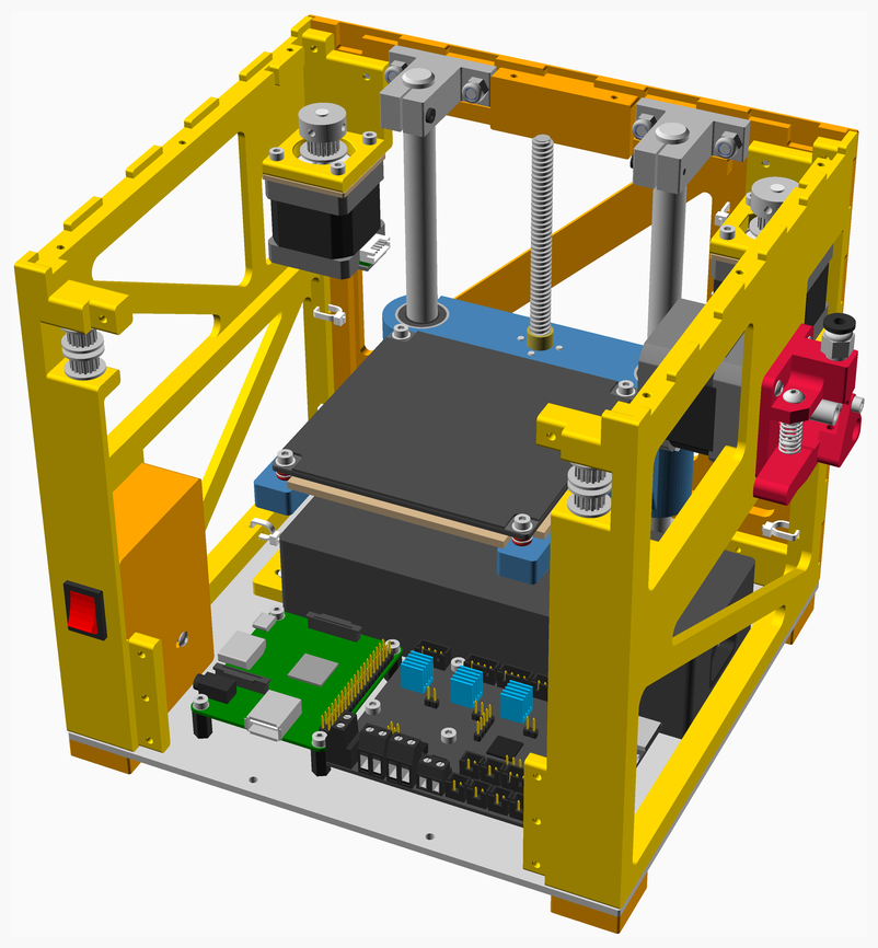
Add the **Back_Face** and bolt it to the left and right faces and the base.
[Top](#TOP)
---
## Stage_3 assembly
### Vitamins
| Qty | Description |
|----:|:------------|
| 2 | Bolt M3 buttonhead x 10mm |
| 8 | Bolt M3 countersunk x 10mm |
### 3D Printed parts
| 1 x Front_Upper_Chord.stl |
|----------|
|  |
### Sub-assemblies
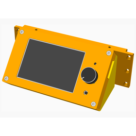
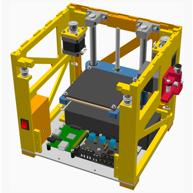
| 1 x Display_Housing_assembly | 1 x Stage_2_assembly |
|----------|----------|
|  |  |
### Assembly instructions
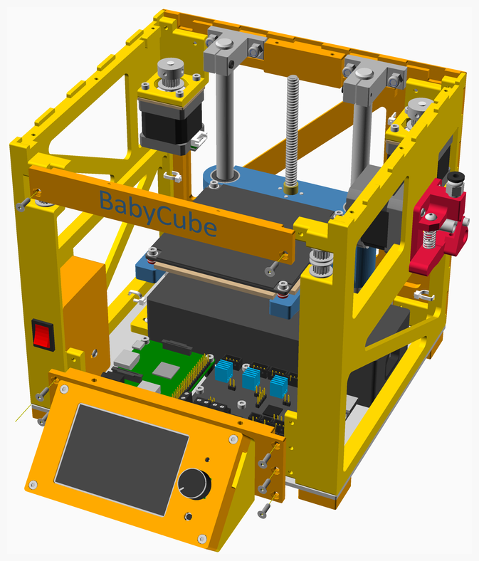
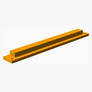
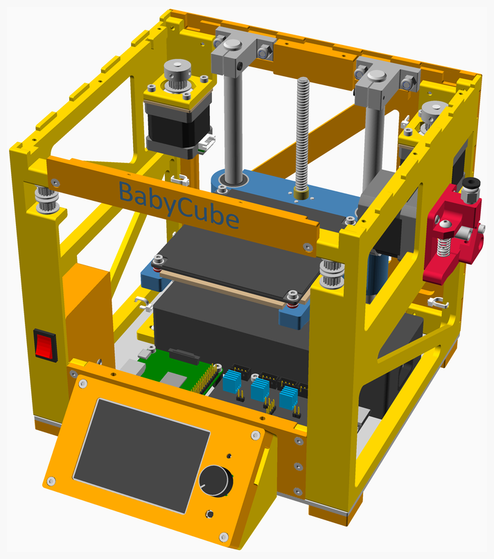
Bolt the BabyCube nameplate and the **Display_Housing** to the front of the frame.
[Top](#TOP)
---
## Stage_4 assembly
### Vitamins
| Qty | Description |
|----:|:------------|
| 10 | Bolt M3 buttonhead x 12mm |
### Sub-assemblies
| 1 x Stage_3_assembly | 1 x Top_Face_assembly |
|----------|----------|
| 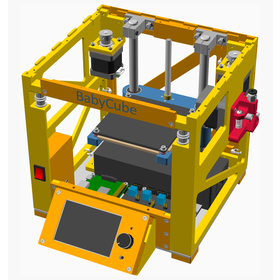 | 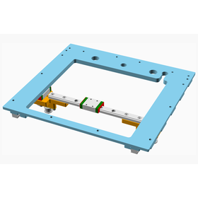 |
### Assembly instructions
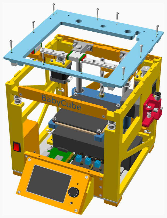
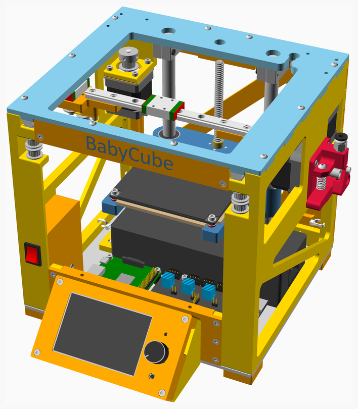
Add the **Top_Face**.
[Top](#TOP)
---
## Stage_5 assembly
### Vitamins
| Qty | Description |
|----:|:------------|
| 1 | Belt GT2 x 6mm x 742mm |
| 1 | Belt GT2 x 6mm x 742mm |
| 2 | Bolt M3 countersunk x 10mm |
| 2 | Bolt M3 countersunk x 12mm |
### 3D Printed parts
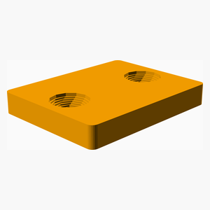
| 1 x X_Carriage_Belt_Clamp.stl |
|----------|
|  |
### Sub-assemblies
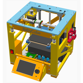
| 1 x Stage_4_assembly | 1 x X_Carriage_Belt_Side_MGN9C_HC_assembly |
|----------|----------|
|  |  |
### Assembly instructions
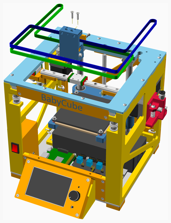
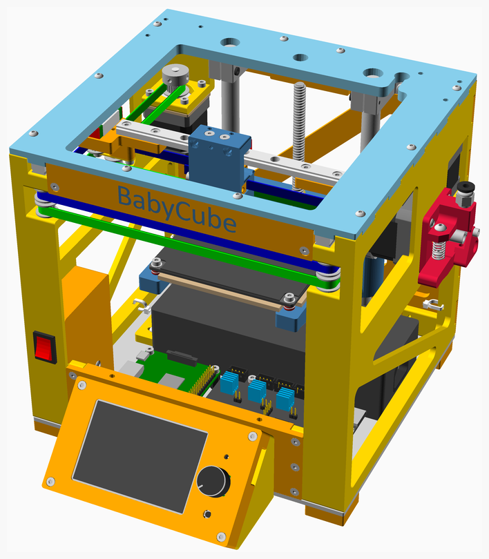
1. Add the Printhead.
2. Thread the belts in the pattern shown.
3. Adjust the belts tension.
[Top](#TOP)
---
## main assembly
### Vitamins
| Qty | Description |
|----:|:------------|
| 2 | Bolt M3 countersunk x 12mm |
| 4 | Bolt M3 countersunk x 30mm |
| 1 | PTFE tube 295 mm |
| 1 | Spiral wrap, 500mm |
### 3D Printed parts
| 1 x Spool_Holder.stl |
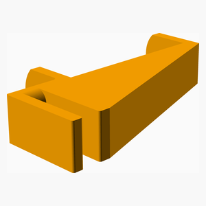
|----------|
|  |
### Sub-assemblies
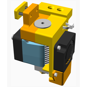
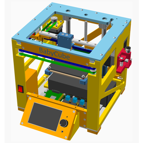
| 1 x Printhead_E3DV6_MGN9C_HC_assembly | 1 x Stage_5_assembly |
|----------|----------|
|  |  |
### Assembly instructions
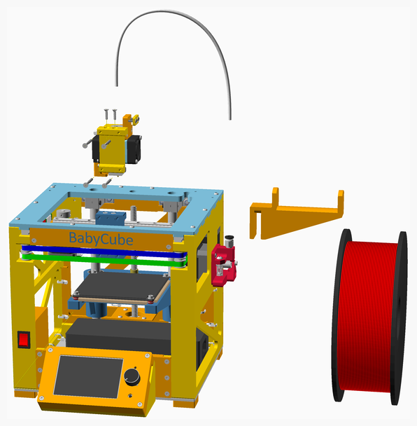
1. Connect the wiring to the printhead.
2. Connect the Bowden tube.
3. Add the S**pool_Holder**.
4. Calibrate the printer.

[Top](#TOP)