{
"cells": [
{
"cell_type": "markdown",
"metadata": {},
"source": [
"# Motorola Radius SM 50/120\n",
"\n",
"
This work is licensed under a Creative Commons Attribution-ShareAlike 4.0 International License.\n",
"\n",
"The Motorola Radius SM-series radios are discontinued land-mobile radios (FCC Part 90) that are available used for under $50. The VHF models can be converted to work on the 2m band, making them an inexpensive option for a dedicated APRS radio.\n",
"\n",
"This article goes over the features of the radio, what you will need to set it up as a dedicated APRS/packet radio, how to program it for the 2m ham band, and my failed attempt to make it work for 9600 baud.\n",
"\n",
"Making these work isn't for everyone. You have to be a little technically adventurous. But if you want a mobile packet radio for very little money, this could be for you.\n",
"\n",
"If you are still reading, this article assumes you can read and understand basic schematic diagrams, have a soldering iron, can build your own cables, and can create basic circuits on a breadboard.\n",
"\n",
"The article assumes you will be connecting the radio to a Mobilinkd TNC3, and have another APRS-capable transceiver for testing. You should also have a dummy load capable of 25W or more, and an RTL SDR.\n",
"\n",
"\n",
"\n",
"## Introduction\n",
"\n",
"One of the more common questions I get at Mobilinkd is for recommendations for inexpensive mobile radios that would work well for APRS or 1200 baud packet. That has not been something I have ever felt qualified to answer. To date Mobilinkd only provides cables for amateur mobile radios with a standard MiniDIN-6 data port. *Les Poston WY0GTR* over at [HamMadeParts](http://www.hammadeparts.com) makes cables that work with our TNCs for a number of other ham radios.\n",
"\n",
"I have done a [review the the ubiquitous KT-8900D](http://www.mobilinkd.com/2017/05/27/a-brief-review-of-the-kt-8900d/), which is rebranded under many names and model numbers, and discussed [why it is unsuitable for APRS](http://www.mobilinkd.com/2017/05/28/kt-8900d-review-follow-up-1/).\n",
"\n",
"Recently I started to get interested in this question of inexpensive mobile radios for another reason. I have been working on adding 9600 baud support to the TNC3. And to do 9600 baud, you really need a mobile radio. The only hand-held radios capable of 9600 baud have built-in TNCs and are rather expensive. And all of the amateur mobile radios that are 9600 baud capable are fairly expensive as well. Partly inspired by the folks at [TARPN](http://tarpn.net/t/packet_radio_networking.html), I wanted to see what was possible for under $100 in the US.\n",
"\n",
"This means foregoing ham radios and going for used commercial gear.\n",
"\n",
"And the focus is going to be on finding radios for dedicated APRS/packet use rather than a do-it-all radio. These are radios you can put in the trunk of your car, or set up as a packet node or digipeater/iGate. Voice communication is a secondary concern.\n",
"\n",
"Because of their nature they won't have VFO knobs, or allow you to enter a specific frequency. They are channelized.\n",
"\n",
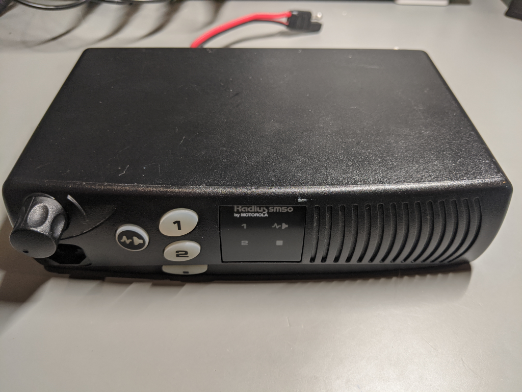
"## Motorola Radius SM50\n",
"\n",
"In my search for inexpensive radios that might be usable for 9600 baud, I came across the Motorola Radius SM50 which I was able to purchase for $30. I had hopes that it could work for 9600 baud as it has flat audio input and output on an accessory port. But even if it was not capable of 9600 baud, it might be a great radio for APRS.\n",
"\n",
"I did a little research at the [Repeater Builder website](http://www.repeater-builder.com/motorola/sm50/sm50.html). There was a lot of detailed information about this radio, including a service manual with full schematics. The service manual is a fairly low-resolution image scan, so it is not searchable and some of the images can be difficult to decipher.\n",
"\n",
"### Model Variations\n",
"\n",
"There are two very similar models in this series -- the SM50, which is a 2-channel radio, and the SM120, which is a 16 channel radio. For this discussion, either will work for a dedicated APRS or packet radio.\n",
"\n",
"More importantly, there are UHF and VHF versions of this radio. The one we need for APRS is the VHF version.\n",
"\n",
"Second, there are 25 watt and 40 watt variants. These can all be determined based on the model number. The [Repeater Builder page](http://www.repeater-builder.com/motorola/sm50/sm50.html) has breakdown of what each component of the model number means. In the end, you want one of these four models:\n",
"\n",
" * M33DGC20A2AA (SM50 VHF 25W) <-- this is the one I purchased.\n",
" * M43DGC20A2AA (SM50 VHF 40W)\n",
" * M33DGC20C2AA (SM120 VHF 25W)\n",
" * M43DGC20C2AA (SM120 VHF 40W)\n",
"\n",
"I prefer the simplicity of the two-channel SM50. But having 16 channels (really 16 \"modes\") offers more flexibility.\n",
"\n",
"### eBay Pricing\n",
"\n",
"The radio pictured above is the exact radio I purchased for $30. That is a reasonable price for the radio. But there are sellers asking more than twice that. They just are not worth much more than what I payed, maybe a bit more if they come with needed accessories (see below). The reason is that these are commercial (FCC Part 90) and there are a bunch of land mobile radios on the market as municipalities switch over to newer digital radios.\n",
"\n",
"In the $60 price range you can get even better radios. I'll do a separate article on a radio in this price range later.\n",
"\n",
"If a seller is trying to sell one at a high price, don't be afraid to offer them what its worth. Lots of people sell stuff on eBay with no clue as to its actual worth. And, in the end, if it is worth $100 to them, they should certainly keep it!\n",
"\n",
"\\[Note: this is written in Spring of 2020. Pricing can change dramatically over time.\\]\n",
"\n",
"## Accessories\n",
"\n",
"One of the things to note is that I purchased the radio you see at the top of the page. Nothing more, nothing less. This means that things you might get with a new radio were missing. I did not get a microphone. I did not get a power cable.\n",
"\n",
"To get this working, you going to need to buy a few accessories.\n",
"\n",
"\n",
" \n",
"  | \n",
"  | \n",
"  | \n",
"
\n",
"
\n",
"\n",
"\n",
"### Antenna Adapter\n",
"\n",
"The radio has a mini-UHF connector for the antenna. I don't have any mini-UHF adapters or cables. I purchased a *Mini-UHF to BNC* adapter for $5.\n",
"\n",
"### Power Cable\n",
"\n",
"The radio has an SAE power connector. These are fairly common in the US. I didn't really need a power cable while it was on the bench. I plugged it into a bench supply using alligator clips. But I will likely put this in a vehicle, so I purchased a power cable. You can find these [on Amazon](https://amzn.to/33MoIu6) for about $10.\n",
"\n",
"### Microphone\n",
"\n",
"For APRS, one does not really need a microphone. I bought one anyway. I don't have a Motorola mic in the lab and I wanted to see how well this radio would work for APRS Voice Alert. These can be found for about $10-15 new. [This is the one I purchased](https://amzn.to/2UjM0Ve). These plug in to a standard RJ-45 connector at the front of the radio.\n",
"\n",
"### Programming Cable\n",
"\n",
"You can buy a programming cable (called a RIB Box), but they cost almost as much as the radio. I built a programming cable using parts I had in my junk drawers. Instructions for how to do that are below.\n",
"\n",
"### Summary\n",
"\n",
"All in, I spent another $30 on parts. But you can get away with spending less than half that.\n",
"\n",
"## Hardware Walkthough\n",
"\n",
"Let's take a quick look at the hardware.\n",
"\n",
"### Front\n",
"\n",
"\n",
" \n",
"  | \n",
"  | \n",
"
\n",
"
\n",
"\n",
"On the front we have the following features:\n",
"\n",
" 1. A power/volume control knob.\n",
" 1. An RJ-45 jack for a speaker-mic and for programming.\n",
" 1. A monitor button to either ignore PL tones and use carrier squelch or open squelch completely.\n",
" 1. Two channel selector buttons. On the SM50 they are labeled 1/2 and on the SM120 they are up/down. These are also referred to as \"modes\" by Motorola.\n",
" 1. An option button whose function can be programmed by the user.\n",
" 1. A channel/mode indicator.\n",
" 1. Indicators for option and monitor indicators.\n",
"\n",
"### Rear\n",
"\n",
"\n",
" \n",
"  | \n",
"  | \n",
"
\n",
"
\n",
"\n",
"On the rear we have three notable items:\n",
"\n",
" 1. The MiniUHF antenna connector.\n",
" 1. The power cable with SAE connector.\n",
" 1. The 16-pin accessory port.\n",
"\n",
"This is really the business end of the radio for APRS use and where we will focus most of our attention.\n",
"\n",
"#### Antenna Connector\n",
"\n",
"There is not a lot of cables or antennas for the ham bands that use MiniUHF. You will want to get an adapter for either SO-239 (female UHF) or, my preference, female BNC. I picked up a male mini-UHF to female BNC for under $5.\n",
"\n",
"You can find them for under $2 from China -- including postage.\n",
"\n",
"It should go without saying that you will also need an antenna for the radio.\n",
"\n",
"#### Power Connector\n",
"\n",
"My radio came with an intact power cable. Unfortunately you see a lot of these radios where it looks like someone just cut the cable while removing it from the last vehicle it was in. Repairing a power cable is trivial. And you can get replacement cables for these radios for under $10. Just search for \"Motorola 3080486U01 Power Cable with Strain Relief\".\n",
"\n",
"These cables have a polarity to them. If you buy a power cord for it, make sure the polarity is correct.\n",
"\n",
"These are soldered to the board, so you will need a soldering iron to replace the cable.\n",
"\n",
"#### Accessory Port\n",
"\n",
"The accessory port is one of the things that drew me to the radio. The pins have a standard 0.1\" (2.54mm) spacing. You can plug standard Dupont connectors into these pins.\n",
"\n",
"You can also get locking connectors for these ports for about $2 on DigiKey. These are [TE Connectivity 104422](https://www.digikey.com/product-detail/en/te-connectivity-amp-connectors/104422-1/104422-1-ND/289312) connectors.\n",
"\n",
"The accessory port has a number of standard pins such as audio input and output, PTT, GND, speaker, ignition sense, and carrier squelch detect. It also has a number of progammable IO pins. You can add an auxilliary PTT signal, for example.\n",
"\n",
"It has flat audio input. The audio output can be programmed to be either squelched and de-emphasized or open with a flat response.\n",
"\n",
"For a full pinout of this port, please refer to the detailed description on the [SM50 information page](http://www.repeater-builder.com/motorola/sm50/sm50.html) at the Repeater Builder website.\n",
"\n",
"For APRS and packet use, we are going to make use of pins 5,7,9,11, which are the top, middle 4 pins. You may need to use 2,3,7,11 for Voice Alert.\n",
"\n",
"### Resources\n",
"\n",
"There are two invaluable resources for information on the radio hardware, both at the Repeater Builder website.\n",
"\n",
" 1. http://www.repeater-builder.com/motorola/sm50/sm50.html This is the main SM50 information page.\n",
" 2. http://www.repeater-builder.com/motorola/manuals/sm50+sm120-svc-man-6880903z45-a.pdf The service manual for the radios.\n",
"\n",
"## Programming\n",
"\n",
"Programming the radio is probably one of the bigger challenges for people. The software to program it is not exactly freely available (original link removed due to spam). And it was made 25+ years ago for MS-DOS.\n",
"\n",
"But I was able to make a programming cable for next to $0, using parts I had in my junk bins. And the programming software worked flawlessly under [DOSBox](https://www.dosbox.com/wiki/Main_Page) on Linux.\n",
"\n",
"When talking about Motorola radios you'll see a lot of talk about RSS, code plugs, and RIBs. It's good to know what these terms mean, but I am going to stick to common terminology and avoid Motorola jargon. RSS is the programming software, code plugs are just radio configuration data, and RIBs are programming cables.\n",
"\n",
"In this section we are going to:\n",
"\n",
" 1. Build a programming cable\n",
" 1. Install and configure DOSBox\n",
" 1. Download and install the programming software\n",
" 1. Read an save the radio's current configuration\n",
" 1. Modify the programming software to allow programming 2m ham band frequencies\n",
" 1. Configure the radio's accessory port\n",
" 1. Program in the APRS channels\n",
"\n",
"So, let's get started!\n",
"\n",
"### Programming Cable\n",
"\n",
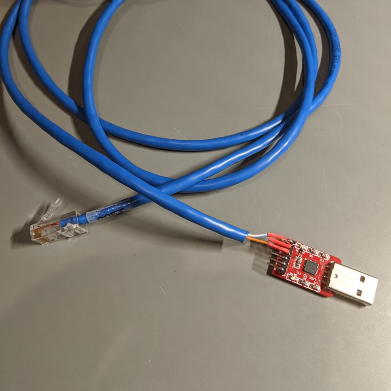
"Programming cables for these radios can be purchased from various online sources. But they are not exactly cheap. They are also very easy to make using a USB UART adapter, a 1N4148 diode, and an old RJ-45 Ethernet cable.\n",
"\n",
"The progamming interface uses a one-wire serial bus. Our programming cable has to convert a two-wire serial bus into a one-wire signal. The protocol used on the Motorola is as simple as it gets, where the transmitter receives everything it sends.\n",
"\n",
"*George Smart M1GEO* has a [schematic diagram](https://www.george-smart.co.uk/scrapbook/gm300_cables/) for a very simple programmer that works really well.\n",
"\n",
"\n",
"\n",
"Things yourll need:\n",
"\n",
" 1. A USB to TTL UART. It needs to be able to handle 3.3V & 5V.\n",
" 1. A general purpose switching diode, such as the 1N4148. Just about any will work.\n",
" 1. An old Ethernet cable with an RJ-45 connector.\n",
" 1. A DMM or continuity tester with sharp probes.\n",
" \n",
"If you want to solder it like I did, you'll need a soldering iron, some solder, and maybe some shrink tubing.\n",
"\n",
"Review the instructions from M1GEO's site linked above. In the image above you can see the blue/white wire connected to ground (GND), the diode bridging TX and RX UART pins, and the orange wire connected to RX. As simple as it is, I still managed to struggle a bit with it because the labels for TX/RX on the UART adapter I used are swapped.\n",
"\n",
" 1. Cut one end off the Ethernet cable. If it is a long one, just cut the length you need.\n",
" 1. Strip off about 2cm of the the outer insulation from the bare end.\n",
" 1. Find the solid orange and white/blue wires.\n",
" 1. Stip about 1cm of insulation from the orange and white/blue wires.\n",
" 1. Use a continuity tester to verify the two wires correspond with the connections on the RJ-45 connector shown [here](https://www.george-smart.co.uk/wordpress/wp-content/uploads/2016/12/GM300_Programming_Schematic.png). Pin 2 of the RJ-45 should be orange and pin 5 should be blue/white.\n",
" 1. If these do not match up, you have a non-standard cable and need to find out what color wires match these pins. In this document I will be referring to them as orange and blue/white.\n",
" 1. Connect the blue/white wire to ground on the USB UART device.\n",
" 1. Connect the orange wire to the RX pin.\n",
" 1. Connect the diode between the TX and RX pins, with the cathode (the stripe) towards the TX pin.\n",
"\n",
"The one you see above is nicely soldered together. But when I was initially figuring out the radio on the bench, this was all done on a breadboard. If you are just going to program one radio, it doesn't have to be well-engineered.\n",
"\n",
"You can buy a RIB on Amazon or eBay and pay $20-40, or you can make one for next to nothing with parts from your junk drawer.\n",
"\n",
"### Programming Software\n",
"\n",
"*As we go through the programming steps, I am going to be using Fedora Linux. You will need to adjust these commands to suit your operating system of choice.*\n",
"\n",
"To program the SM50, you will need to google for \"RSS SM50\". I provided a link above to a site that has the software. This is DOS-based software. In this section I am going to show you how to configure DOSBox, run the software, make some required changes so we can program frequencies in the 2m ham band, and then program the radio for 2m APRS.\n",
"\n",
"#### Download the Programming Software\n",
"\n",
"You will need to download the `SM50/SM120 R04.00.00 RSS` from ... (Apologies -- the original link now point to a spam site. You will need to find a suitable replacement. -- 2023-08-30)\n",
"\n",
"Create a directory under your home directory called SM50 (for me, that's `/home/rob/SM50`), download and unzip the\n",
"file there.\n",
"\n",
" mkdir ~/SM50\n",
" cd ~/SM50\n",
" wget ...\n",
" unzip Sm50_1.zip\n",
"\n",
"After you unzip the ZIP file, you will find a self-extracting archive called SM.EXE.\n",
"\n",
"The next step is to plug in your programming cable and determine the device name assigned. For me that's `/dev/ttyUSB5` or `/dev/serial/by-id/usb-Silicon_Labs_CP2102_USB_to_UART_Bridge_Controller_0001-if00-port0`.\n",
"\n",
"Leave the programming cable plugged in.\n",
"\n",
"#### Installing & Configuring DOSBox\n",
"\n",
"Next, if you don't already have DOSBox installed, install it:\n",
"\n",
" sudo dnf install dosbox\n",
"\n",
"Now we need to start DOSBox at least once. When you start up DOSBox the first time, it will create a configuration file in `~/.dosbox/dosbox-0.74-3.conf`. We need to edit this file. If that file (or one with a similar version number) does not exist, start DOSBox and then just close the window that opens.\n",
"\n",
"We need to edit the config file.\n",
"\n",
" gedit ~/.dosbox/dosbox-0.74-3.conf &\n",
" \n",
"Specifically, we need to edit two sections near the end. The first is the `[serial]` section.\n",
"\n",
" [serial]\n",
" serial1=directserial realport:serial/by-id/usb-Silicon_Labs_CP2102_USB_to_UART_Bridge_Controller_0001-if00-port0\n",
"\n",
"Change the device to match your own. This maps our USB serial device to COM1 on DOS. Note that the `/dev/` prefix is missing from the path. You can also do:\n",
"\n",
" serial1=directserial realport:ttyUSB5\n",
"\n",
"The drawback with this method is that you may have to change it frequently if you change USB connections regularly. You will end up with different tty port assignments.\n",
"\n",
"The next section we need to change is the `[autoexec]` section.\n",
"\n",
" [autoexec]\n",
" # Lines in this section will be run at startup.\n",
" # You can put your MOUNT lines here.\n",
"\n",
" mount d /home/rob/SM50\n",
" D:\n",
"\n",
"Change the path to where you created it. This mounts the directory as a DOS drive (drive D:) and changes to drive D:.\n",
"\n",
"#### Install the Programming Software\n",
"\n",
"Next we need to run the self-extracting archive in dosbox. If you have configured the drive correctly, you can run:\n",
"\n",
" dosbox SM.EXE\n",
"\n",
"Capitalization is important here. This will open a DOSBox window with the extraction running. This is an interactive program, you will will need to respond.\n",
"\n",
"\n",
" \n",
"  | \n",
"  | \n",
"
\n",
"
\n",
"\n",
"Answer \"Y\" to all of the questions.\n",
"\n",
"### Reading the Radio\n",
"\n",
"You can now plug the programming cable into the radio and power on the radio.\n",
"\n",
"The first thing we are going to do is read the radio configuration and save it as a backup.\n",
"\n",
"#### Reading and Saving the Radio Configuration\n",
"\n",
"Once that is done, you can type `SM50` in the DOSBox window and start the application. Press the \"Any Key\" to continue. This brings us to the main menu.\n",
"\n",
"\n",
" \n",
"  | \n",
"  | \n",
"
\n",
"
\n",
"\n",
"One thing to note about the SM50 configuration software is that it is very much driven by function keys. Navigation is done via function keys, tab/shift-tab and the up/down keys. The escape key always takes you back to the main menu.\n",
"\n",
"##### GET/SAVE Codeplug\n",
"\n",
"The first thing we need to do is to read the configuration from the radio. Press F3 -- `GET/SAVE Codeplug`.\n",
"\n",
"In the GET/SAVE menu, press F2 -- `READ Data From Radio Codeplug`.\n",
"\n",
"\n",
" \n",
"  | \n",
"  | \n",
"
\n",
"
\n",
"\n",
"If everything works as it should, this second screen should pop up while it reads from the radio, and the return you to the GET/SAVE menu. You should also hear the radio beep as it leaves programming mode.\n",
"\n",
"If this does not work, you will need to check your serial adapter and cable connections. Make sure that dosbox opened the serial port successfully.\n",
"\n",
"When it finishes reading the radio configuration, you will see the radio model in the upper right panel.\n",
"\n",
"##### SAVE Codeplug Data to Disk\n",
"\n",
"The next step is to save this to disk. Press F7 -- `SAVE Codeplug Data to Archive File Disk`.\n",
"\n",
"Change the archive path to `D:\\ARC` and press enter. Add a meaningful name in the *Customer ID* box. I called mine ORIGINAL. Press F8 to save the file.\n",
"\n",
"It will then want to write the backup to a diskette as well. We don't need to do that. We are just going to press F10 to exit here.\n",
"\n",
"\n",
" \n",
"  | \n",
"  | \n",
"
\n",
"
\n",
"\n",
"We are then going to press F10 again to get back to the main menu.\n",
"\n",
"#### Viewing the Configuration\n",
"\n",
"Press F4 -- `CHANGE/VIEW Codeplug`. Then press F2 -- `RADIO WIDE Configuration`.\n",
"\n",
"This gives us information about the radio based on the model information, such as power output, the frequency range it supports, and the number of channels (labelled *conventional modes*).\n",
"\n",
"\n",
" \n",
"  | \n",
"  | \n",
"
\n",
"
\n",
"\n",
"The thing to note here is that the frequency range supported, 150-170MHz is outside the 2m ham band. This information is hardcoded into the RSS software's own configuration file. We need to change this in order to get the radio to operate in the 2m ham band.\n",
"\n",
"It was important to read the radio configuration and save it with the unpatched version of the software before making this change.\n",
"\n",
"At this point we need to exit the programming softare and make some changes. Press F10 as many times as needed to get back to a DOS prompt. Then close the DOSBox window. We are going back to the Linux terminal window.\n",
"\n",
"### Patching the Software\n",
"\n",
"The SM50.MDF file in the SM50 directory contains hard-coded band ranges based on model number. There are a few online documents which show how to change this file. They are all manual processes that are prone to error.\n",
"\n",
"To make this process easier, I wrote a program in Python that edits the file, shifting the range of the radio down 6MHz to 144-164MHz.\n",
"\n",
"Download the program [mdfham2m.py](mdfham2m.py) from this repository and put it in the ~/SM50/ directory where we unzipped the RSS program. This is where the SM50.MDF file is. Then run the program, giving it the SM50.MDF filename as a command-line parameter.\n",
"\n",
" cp ~/Downloads/mdfham2m.py .\n",
" ./mdfham2m.py SM50.MDF\n",
"\n",
"This will modify the file and write a backup of the original.\n",
"\n",
"\n",
" \n",
"  | \n",
"
\n",
"
\n",
"\n",
"### Configuring the Radio\n",
"\n",
"Start up DOSBox again, this time giving it the SM50.EXE command to run.\n",
"\n",
" dosbox SM50.EXE\n",
"\n",
"This will launch straight into the programming software. We need to read the radio configuration again, then go back to the radio-wide configuration screen. You can follow the steps below or refer to the steps we went through above you if get lost.\n",
"\n",
" 1. Press the any key to get to the main menu.\n",
" 1. Press F3 -- `GET/SAVE Codeplug`.\n",
" 1. Press F2 -- `READ Data From Radio Codeplug`.\n",
" 1. Press F10 -- `EXIT/Return To MAIN Menu` to get back to the main menu.\n",
" 1. Press F4 -- `CHANGE/VIEW Codeplug`.\n",
" 1. Press F2 -- `RADIO WIDE Configuration`.\n",
" \n",
"Now we can see that the radio supports the 2m ham band!\n",
"\n",
"#### Accessory Port Configuration\n",
"\n",
"Press F9 -- `OTHER ACCESSORY`. This will let us modify the accessory port on the back of the radio.\n",
"\n",
"\n",
" \n",
"  | \n",
"  | \n",
"
\n",
"
\n",
"\n",
"We need to make three changes here:\n",
"\n",
" 1. Set the `Acc. Rx Audio` to `Unmuted`.\n",
" 1. Set the `Current Limiter` to `Post`.\n",
" 1. Set the pin 9 function to `External PTT`.\n",
"\n",
"Use the tab and shift-tab to navigate forwards and backwards. Use the up/down keys to change selections.\n",
"\n",
"When you are done, press F10 twice to exit back to the `CHANGE/VIEW CODEPLUG MENU`.\n",
"\n",
"#### Channel Configuration\n",
"\n",
"Press F5 -- `MODE Configuration`. This will let us change the two channels (or modes). The reason they are called modes is that they can refer to the same frequency, but with parameters like power output or squelch type changed.\n",
"\n",
"We're going to set the first channel to the North American APRS frequency, and the second channel to the ARISS/satellite APRS frequency (we have a lot of APRS satellites at the moment). We are going to use low-power for the ARISS channel.\n",
"\n",
"Set the modes as shown. Use F4 to switch between the modes.\n",
"\n",
"\n",
" \n",
"  | \n",
"  | \n",
"
\n",
"
\n",
"\n",
"Press F10 twice when you are done to get back to the main menu.\n",
"\n",
" 1. Press F3 -- `GET/SAVE Codeplug`.\n",
" 1. Press F8 -- `PROGRAM Data Into Radio Codeplug`\n",
" 1. Press F2 -- `CONTINUE`\n",
" \n",
"\n",
"\n",
" \n",
"  | \n",
"  | \n",
"
\n",
"
\n",
"\n",
"Congratulations! You have programmed your SM50 for APRS. In the next section, we are going to make a cable to connect the radio to a TNC3 and test it out.\n",
"\n",
"## TNC Cable\n",
"\n",
"In this section we are going to build a basic TNC cable using an IDC cable with female Dupont connectors and a [3.5mm 4-pole connector](https://store.mobilinkd.com/collections/connectors/products/3-5mm-4-pole-trrs-male-plug-tnc-connector).\n",
"\n",
"We are also going to convert the basic cable to one that is custom designed for this radio.\n",
"\n",
"### Basic Cable Construction\n",
"\n",
"We are going to start building the basic cable. This is also the foundation for the advanced cable, so start here.\n",
"\n",
"You will need the following:\n",
"\n",
" 1. A strip of 4 wires from an IDC connector with female Dupont connectors on at least one end. This is what I used: [Breadboard Jumper Wires Ribbon Cables Kit](https://amzn.to/3dBU1N1)\n",
" 1. A [3.5mm 4-pole connector](https://store.mobilinkd.com/collections/connectors/products/3-5mm-4-pole-trrs-male-plug-tnc-connector)\n",
" 1. Diagonal cutters.\n",
" 1. Wire stripper/crimper.\n",
" 1. A soldering iron.\n",
" 1. Fine 0.5mm rosin core solder.\n",
" \n",
" \n",
" \n",
"  | \n",
"  | \n",
"
\n",
"
\n",
"\n",
"Construction steps:\n",
"\n",
" 1. With the strip of 4 wires, cut the ends off one end, leaving four female Dupont connectors on the other end.\n",
" 1. Separate the sleeve from the plug of the 3.5mm connector.\n",
" 1. Slide the plastic sleeve over the 4 wires.\n",
" 1. Strip about 4mm (5/32\") of insulation from each wire.\n",
" 1. Make sure the connector sleeve is over the 4 wires.\n",
" 1. Solder the connectors in order: sleeve, ring 2, ring 1, tip. This is so you can look at the cable and know which wire is which.\n",
" 1. Verify once more that you slid the connector sleeve over the 4 wires.\n",
" 1. Crimp the connector over the wires for strain relief.\n",
" 1. Screw the plastic sleeve onto the plug.\n",
" \n",
"#### Prep\n",
"\n",
"Prep the cable by cutting the ends off of one end of the cable, unscrewing the sleeve from the plug, sliding the sleeve over the IDC cable, and stripping 4mm of insulation from the ends. Verify the order in which you will be soldering the wires.\n",
"\n",
" \n",
" \n",
"  | \n",
"  | \n",
"  | \n",
"
\n",
"
\n",
"\n",
"#### Solder\n",
"\n",
"Soldering the connector and getting the connections right is easy if you use the 3.5mm connector from the Mobilinkd store. Start at the bottom connecting the sleeve and then go counter-clockwise in order to ring 2, ring 1 and the tip.\n",
"\n",
" \n",
" \n",
"  | \n",
"  | \n",
"
\n",
" \n",
"  | \n",
"  | \n",
"
\n",
"
\n",
"\n",
"#### Crimp\n",
"\n",
"Crimp the connector to the insulation of the wires, being careful not to damage the insulation. Thread the sleeve onto the plug.\n",
"\n",
"\n",
" \n",
"  | \n",
"  | \n",
" | \n",
"
\n",
"
\n",
"\n",
"\n",
"That's it. The cable is ready.\n",
"\n",
"#### Connect Radio to TNC\n",
"\n",
"The pinout of the cable is as follows:\n",
"\n",
" * Tip: SPKR -- Radio audio output / TNC audio input.\n",
" * Ring 1: PTT -- Key the transmitter.\n",
" * Ring 2: MIC -- Radio audio input / TNC audio output\n",
" * Sleeve: GND -- Common\n",
"\n",
"\n",
"We are now ready to connect the radio to a TNC. Just plug the wires in like so:\n",
"\n",
"|Left|_|_|Top|_|_|Ri|ght|\n",
"|--|--|--|--|--|--|--|--|\n",
"|15|13|SPKR|PTT|GND|MIC|03|01|\n",
"|16|14|12|10|08|06|04|02|\n",
"\n",
"Then plug the cable into the TNC3.\n",
"\n",
"\n",
" \n",
"  | \n",
"  | \n",
"  | \n",
"
\n",
"
\n",
"\n",
"If you want to use APRS Voice Alert, you will need to connect the TNC to the radio slightly differently. In fact, this is probably the most useful configuration. After completing this article, what you see below is the recommended pinout to use.\n",
"\n",
"\n",
"|Left|_|_|Top|_|_|Ri|ght|\n",
"|--|--|--|--|--|--|--|--|\n",
"|15|13|SPKR|09|GND|05|PTT|01|\n",
"|16|14|12|10|08|06|04|MIC|\n",
"\n",
"Connect the TNC PTT and MIC wires to the *External Mic PTT* (pin 3) and *External Mic Audio* (pin 2) inputs on the accessory connector.\n",
"\n",
"\n",
" \n",
"  | \n",
"
\n",
"
\n",
"\n",
"You can skip the next step and come back to it later. This cable is perfectly usable to get started with the radio.\n",
"\n",
"### Advanced Cable\n",
"\n",
"To constuct the advanced cable, you will need the following additional items:\n",
"\n",
" 1. The basic cable we constructed earlier.\n",
" 1. A [TE Connectivity 104422](https://www.digikey.com/product-detail/en/te-connectivity-amp-connectors/104422-1/104422-1-ND/289312) connector.\n",
" 1. A small zip tie.\n",
" 1. A hot glue gun.\n",
" 1. An Exacto knife or similar thin pointy tool.\n",
" 1. Some tape.\n",
"\n",
"Use the Exacto knife to pry up the small plastic tab on the Dupont connector, releasing the crimped wire on all four wires. These are going to slide straight into the 16-pin connector.\n",
"\n",
"\n",
" \n",
"  | \n",
"  | \n",
"  | \n",
"
\n",
"
\n",
"\n",
"\n",
"The radio's 16-pin connector looks like this:\n",
"\n",
"|Left|_|_|Top|_|_|Ri|ght|\n",
"|--|--|--|--|--|--|--|--|\n",
"|15|13|11|09|07|05|03|01|\n",
"|16|14|12|10|08|06|04|02|\n",
"\n",
"\n",
"Since you've been using the cable constructed early to connect to the radio and test it out, this should be familiar to you by now.\n",
"\n",
"We are going to connect the cable like so:\n",
"\n",
"|Left|_|_|Top|_|_|Ri|ght|\n",
"|--|--|--|--|--|--|--|--|\n",
"|15|13|SPKR|PTT|GND|MIC|03|01|\n",
"|16|14|12|10|08|06|04|02|\n",
"\n",
"Push the wires into the connector. Tape the wires down to the plastic tab. Test the cable with the TNC.\n",
"\n",
"\n",
" \n",
"  | \n",
"  | \n",
"
\n",
"
\n",
"\n",
"If everything works, use the zip tie to fasten the cable to the connector but running it through two of the holes and over the cable.\n",
"\n",
"\n",
" \n",
"  | \n",
"
\n",
"
\n",
"\n",
"\n",
"## 1200 Baud APRS\n",
"\n",
"At this point we have the TNC3 connected to the SM50. In this section we are going to run through the configuration steps for the TNC using the Mobilinkd Config App for iOS and use the aprs.fi app on iOS to send and receive our first packets.\n",
"\n",
"### Equipment Needed\n",
"\n",
"To configure the radio and the TNC, we need a few pieces of equipment. Besides the Motorola SM50 radio, the Mobilinkd TNC3, and the cable we built earlier, we will need the following:\n",
"\n",
" 1. A dummy load.\n",
" 1. RF cables and adapters to connect the radio to the dummy load.\n",
" 1. An RTL SDR (one with a TXCO is best), along with antenna.\n",
" 1. Software such as GQRX or SDR# to view the RF spectrum.\n",
" 1. An Android or iOS phone to run the TNC configuration app.\n",
" \n",
"We will go through the steps below using GQRX on Linux. This assumes you have installed the Mobilinkd Config App on your phone and that you are familiar with its use. We will be using the iOS version of this app.\n",
" \n",
"You will see me using 144.910MHz for testing, but you can use whatever frequency is easiest. If channel 1 is programmed to 144.390MHz for APRS, use that. I recommend programming the radio for low power while doing this configuration.\n",
"\n",
"I have a large 100W dummy load that I use quite a bit in the lab. However, I also have a [25W 40dB attenuator](https://amzn.to/2R9qqAK) along with a 50Ω terminator that I will use in a pinch. This is a more flexible option for those on a budget. I don't recommend connecting the radio through the attenuator directly to the RTL SDR. Even with 40dB attenuation, it can overdrive the input of the SDR.\n",
"\n",
"There is enough RF emitted via the cables and connectors that can be picked up with an antenna connected to the RTL SDR.\n",
"\n",
"\n",
" \n",
"  | \n",
"  | \n",
"
\n",
"
\n",
"\n",
"Connect the radio to the dummy load, to the TNC and to power.\n",
"\n",
"Connect an antenna to the RTL SDR, plug it into a USB port on the computer, and start GQRX.\n",
"\n",
"\n",
" \n",
"  | \n",
"  | \n",
"
\n",
"
\n",
"\n",
"Start up GQRX. We need to configure the SDR for a narrow frequency span. Click on the \"Configure IO Devices\" icon. Then select the RTL SDR device and configure the input rate for 1.8Msps, 32x decimation, and 50kHZ (0.050MHz) bandwidth.\n",
"\n",
"Next, on the Input Controls tab, configure the input controls for your RTL SDR device. Add any frequency correction necessary.\n",
"\n",
"\n",
" \n",
"  | \n",
"  | \n",
"
\n",
"
\n",
"\n",
"Switch to the Receiver Options tab and set the frequency you will be testing at, the filter width to Wide, the mode to Narrow FT and disable AGC. In the FFT Settings tab, set the FFT size to 8192 and adjust the dispay so that the panadapter (the top part) takes up at least 2/3 of the view. I also recommend muting the output. Click on the images above to get a higher resolution view of the settings.\n",
"\n",
"\n",
" \n",
"  | \n",
"  | \n",
"  | \n",
"
\n",
"
\n",
"\n",
"\n",
"Turn on the radio and the TNC. Open the config app. You should see the TNC appear in the connection screen. Tap the TNC to connect. Tap *Audio Input Settings...* to go to that screen. Tap on *Auto-Adjust Levels*. You should see the audio input a gain set to 0 and the input twist level somewhere close to 0. +/-2dB is normal since we are using flat audio input.\n",
"\n",
"Here is where we will be using GQRX. Press the *Start DSP* button in QGRX.\n",
"\n",
"Tap the back button in the config app and tap *Audio Output Settings...*. Select *Simplex* PTT style, and a 1200Hz test tone. Then tap *Transmit*. You should see the transmission in GQRX on the panadapter and in the waterfall display. It should appear as a set of distinct lines, each 1200Hz appart.\n",
"\n",
"\n",
" \n",
"  | \n",
"
\n",
"
\n",
"\n",
"We are going to use the Bessel Null method to set our output level.\n",
"\n",
"Starting a level of 0, slowly adjust the output level up. You will see more and more peaks appear. At some point you will notice the carrier (the middle frequency peak) start to dip. Adjust the level until the carrier is at its lowest level (see image above). For me, the output level was 172. Fine tuning this level can be a bit challenging in the app. Just know that it does not have to be perfect. Setting the output level a little bit higher than the perfect Null is OK. This provides almost 3kHz deviation. Since we are using the pre-emphasis, the 2200Hz tone will have higher deviation -- somewhere closer to 3.3kHz.\n",
"\n",
"Now that we are done, tap *Back* in the app to go back to the main menu, then tap *Save* to save these settings to the TNC.\n",
"\n",
"That's it. You can now exit the app and close GQRX. At this point you can start up the [aprs.fi](https://apps.apple.com/us/app/aprs-fi/id922155038) app or, if you are using Android, [APRSDroid](https://play.google.com/store/apps/details?id=org.aprsdroid.app).\n",
"\n",
"In the next section we will be exploring 9600 baud operation.\n",
"\n",
"\n",
"## 9600 Baud Modifications\n",
"\n",
"I am going to start right now by telling you that my attempt to modify the radio for 9600 baud failed. I was able to send and receive packets over 9600 baud. But the modification required for transmit had a horrible impact on the behavior of the transmitter.\n",
"\n",
"### Tools and Equipment\n",
"\n",
"We are going to be using a spectrum analyzer, an RTL SDR, a vector signal generator, a function generator, and an oscilloscope. To make simialar changes, you will need good soldering skills. And having access to a bench microscope, such as the [AmScope SE400-Z](https://amzn.to/2xMg5E4), which is what I use, will be helpful.\n",
"\n",
"A note about the test setup.\n",
"\n",
"\n",
" \n",
"  | \n",
"
\n",
"
\n",
"\n",
"\n",
"An HP E4433B vector signal generator is used to generate the 9600 baud GMSK signal to the radio.\n",
"\n",
"To get the eye diagrams you will see below, I used a [Siglent SDG2042X](https://amzn.to/3aKuAH0) arbitrary waveform generator to generate a 9600Hz square wave which was fed into the trigger input of the oscilloscope. The oscilloscope was set to 180us delay and 1s persistence. This delay causes the trigger to occur a number of bit periods before the display. What we see on the screen is the waveform 180us after the trigger.\n",
"\n",
"First off, let's discuss why modification of the radio was necessary.\n",
"\n",
"### Receive Audio\n",
"\n",
"\n",
" \n",
"  | \n",
"  | \n",
"
\n",
"
\n",
"\n",
"When looking at the receive audio that came out of the discriminator, and which was available at the\n",
"feature port *inside the radio*, it was a clean signal, easily usable for 9600 baud demodulation. However, the signal that was present at the *flat audio output* pin of the accessory port on the back was not. It seemed as if there was a high-pass filter in the audio path that was affecting the low frequency response.\n",
"\n",
"\n",
" \n",
"  | \n",
"
\n",
"
\n",
"\n",
"Looking at the schematic and probing around a bit with the oscilloscope, I suspected that C559 was the culprit (or at least part of it).\n",
"\n",
"\n",
" \n",
"  | \n",
"  | \n",
"
\n",
"
\n",
"\n",
"C559 is a 0603 MLCC surface mount capacitor. To test my hypothesis, I soldered a 2.2uF capacitor in parallel, by piggy-backing an 0805 package MLCC on top.\n",
"\n",
"What you see above is the result. The demodulated output looked clean and I was able to decode 9600 baud packets easily.\n",
"\n",
"### Transmit Audio\n",
"\n",
"Transmit audio was a bit trickier. It turns out that flat TX audio isn't flat, and is completely attenuated beyond 3kHz. The audio is routed through the AFIC (Motorola's audio processor IC) U402. There are multiple paths depending on whether the MIC PTT is pressed or an auxilliary PTT signal is used, and whether pre- or post-limiter is selected in the audio path configuration when setting up the accessory port. None of those options provided clean, unfiltered access to the the VCO.\n",
"\n",
"One of the tricks used to make the GM300 support 9600 baud is to bypass the AFIC [as described here](http://www.redwaveradio.com/5_7487f484c875f483_1.htm). I found a similar path on the SM50.\n",
"\n",
"\n",
" \n",
"  | \n",
"  | \n",
"
\n",
"
\n",
"\n",
"This routes the signal when an auxilliary PTT is used around the AFIC and straight into the VCO. I could not quite get R671 into the image through the microscope. Luckily, R671 and R655 & R656 are on the same side of the PCB and near each other.\n",
"\n",
"This worked! I could now send and receive data at 9600 baud.\n",
"\n",
"But something was not right. When I went to fine tune the deviation on the radio using an RTL-SDR and GQRX, I observed the TX frequency jumping around +/- almost 3kHz.\n",
"\n",
"\n",
" \n",
"  | \n",
"
\n",
"
\n",
"\n",
"All of these transmissions should line up perfectly. This is a 1200Hz tone being sent in multiple bursts.\n",
"\n",
"When transmitting just a carrier, by triggering PTT with the output level set to 0, the carrier is always centered on the expected transmit frequency (within its specification).\n",
"\n",
"What I believe happens is that during normal operation the AFIC suppresses the modulation output until after the VCO PLL locks. Bypassing the AFIC and preseting a modulated signal to the VCO before the PLL is locked causes the PLL to lock to the wrong frequency.\n",
"\n",
"The radio always transmits on the proper frequency after modifying the firmware in the TNC to key the transmitter and wait about 60ms (determined empirically) before sending the preamble (TX Delay) and the HDLC frame.\n",
"\n",
"But that is not done on any TNC that I am aware of. What happens (or what is *specified to happen*) is that the transmitter is keyed and either IDLE or FLAG bytes are immediately sent (the standard says FLAG, but there are advantages to sending IDLE).\n",
"\n",
"So, in the end I abandoned my attempt to use this radio for 9600 baud.\n",
"\n",
"The good news is that reverting the change on the TX side eliminated the problem and allowed me to complete the 1200 baud section above using both flat and pre-emphasized TX audio.\n",
"\n",
"## Summary\n",
"\n",
"The SM50 is a fine radio for 1200 baud APRS when it can be found for a reasonable price. Accessories are easy to come by and inexpensive. The programming cable is easy to make. The programming software runs easily in DOSbox on virtually any platform. And the accessory connector allows the use common Dupont connectors when constructing a cable.\n",
"\n",
"While it is unsuitable for 9600 baud operation, the radio is still a very good value for a dedicated mobile APRS radio.\n",
"\n",
"There is further research to be done if there are other modifications possible to achieve 9600 baud without the problems docuemented here. And it may be worth researching whether adding an additional \"modulation delay\" parameter to a TNC, where PTT is engaged without modulation for some time period, would be a generally useful feature to implement.\n",
"\n",
"As others have documented a [similar modification to Motorola MaxTrac radios](http://motorolamaxtrac.blogspot.com/2014/02/maxtrac-radius-9600-baud-packet.html), it may be worthwhile to investigate whether similar transmit frequency errors occur with these radios and, if not, how the problem is avoided in these radios.\n",
"\n",
"I would like to encourage radio manufacturers to make the software required to program their radios publicly and freely available to radio amateurs when the radio equipment is no longer an economically viable products. Requiring that radio amateurs download software from unofficial sites in order to program their equipment is undesireable.\n",
"\n",
"At the same time, I would also encourage more radio amateurs to take on the task of decoding the programming protocols of these radios and providing open software for programming them. [Chirp](https://chirp.danplanet.com/projects/chirp/wiki/Home) is a great resource for a large number of radios.\n",
"\n",
"But since Motorola apparently [encrypts the data between programmer and radio](https://chirp.danplanet.com/issues/1333), it seems will not be an option for owners of Motorola equipment unless Motorola themselves step forward to addres."
]
},
{
"cell_type": "code",
"execution_count": null,
"metadata": {},
"outputs": [],
"source": []
}
],
"metadata": {
"kernelspec": {
"display_name": "Python 3 (ipykernel)",
"language": "python",
"name": "python3"
},
"language_info": {
"codemirror_mode": {
"name": "ipython",
"version": 3
},
"file_extension": ".py",
"mimetype": "text/x-python",
"name": "python",
"nbconvert_exporter": "python",
"pygments_lexer": "ipython3",
"version": "3.11.4"
}
},
"nbformat": 4,
"nbformat_minor": 2
}