{
"cells": [
{
"cell_type": "markdown",
"metadata": {},
"source": [
"# Nucleo TNC\n",
"\n",
"The Nucleo TNC is a breadboard implementation of the [Mobilinkd TNC3](https://store.mobilinkd.com/products/mobilinkd-tnc3) using a STM32L432KC Nucleo32 board. This TNC faithfully implements the audio section and EEPROM storage of the TNC3. It omits the battery charging and Bluetooth components of the TNC3. It presents as a KISS TNC over a USB serial port.\n",
"\n",
"The Nucleo TNC is a 1200 baud KISS TNC built using an inexpensive microcontroller board with great digital signal processing capabilities and very low power consumption. It's an open implementation of our commercial product, the TNC3, designed to encourage experimentation and learning in electronics and software engineering. It's a more advanced version of a [similar project we designed for the Arduino Nano](http://www.mobilinkd.com/2014/09/11/arduino-kiss-tnc/), which was based on our TNC1/TNC2 product.\n",
"\n",
"The Nucleo TNC can be assembled for about $25 in parts, assuming you already have a breadboard and hookup wire. The bill of materials and the equipment needed to build and use the TNC are provided below in the *Bill of Materials* and *Equipment* sections, respectively.\n",
"\n",
"Please join the [Mobilindk Community](https://groups.io/g/mobilinkd) on groups.io to share your builds and for help troubleshooting and using it. Send us pictures of your breadboards. We would love to see them!\n",
"\n",
"This project is intended for amateur radio operators from beginners to advanced. If you want to just dive in to building it without understanding the theory of operations, start at the overview and skip to the BOM and Assembly Instructions. For those who wish to understand the theory of operation from an electrical perspective, we start with the *Schematic* and *Theory of Operation* sections after a brief overview.\n",
"\n",
"And for those who wish to understand the digital signal processing involved in this project, please refer to the [AFSK Demodulator](https://nbviewer.jupyter.org/github/mobilinkd/afsk-demodulator/blob/master/afsk-demodulator.ipynb) tutorial which outlines the basics of how the demodulator is constructed. You can also refer to the source repository for the firmware.\n",
"\n",
"This breadboard TNC has the same radio interface pinout as the Mobilinkd TNCs and is designed to be used with the same cables as a Mobilinkd TNC. Pre-made cables for your radio can be purchased at http://store.mobilinkd.com or you can make your own.\n",
"\n",
"\n",
"\n",
"## Table of Contents\n",
"\n",
" * [Schematic](#Schematic)\n",
" * [Theory of Operation](#Theory-of-Operation)\n",
" * [Radio Connection](#Radio-Connection)\n",
" * [PTT Circuitry](#PTT-Circuitry)\n",
" * [EEPROM](#EEPROM)\n",
" * [Indicator LEDs](#Indicator-LEDs)\n",
" * [Audio Input](#Audio-Input)\n",
" * [Audio Output](#Audio-Output)\n",
" * [Nucleo Board](#Nucleo-Board)\n",
" * [Bill of Materials](#Bill-of-Materials)\n",
" * [Equipment](#Equipment)\n",
" * [Assembly](#Assembly)\n",
" * [Nucleo and ICs](#Nucleo-and-ICs)\n",
" * [Bypass Capacitors](#Bypass-Capacitors)\n",
" * [Power and Ground](#Power-and-Ground)\n",
" * [LEDs](#LEDs)\n",
" * [3.5mm Jack](#3.5mm-Jack)\n",
" * [PTT](#PTT)\n",
" * [EEPROM Connections](#EEPROM-Connections)\n",
" * [Audio Input Circuitry](#Audio-Input-Circuitry)\n",
" * [Audio Output Circuitry](#Audio-Output-Circuitry)\n",
" * [Wiring](#Wiring)\n",
" * [Programming](#Programming)\n",
" * [Operation](#Operation)\n",
" * [Troubleshooting and Testing](#Troubleshooting-and-Testing)\n",
" \n",
"## Overview\n",
"\n",
"The Nucleo TNC is part of a larger system for sending and receiving digital information over the radio. This TNC is designed for 1200 baud AFSK, which means it is designed to send data over an audio channel -- specifically over a standard FM voice channel. One of the more popular uses for this is for APRS. It can also be used for Winlink, or to attach to packet radio BBS systems, and for direct one-on-one communication.\n",
"\n",
"To use this TNC you will need the following:\n",
"\n",
" * A radio -- typically a hand-held radio or mobile radio.\n",
" * The TNC itself.\n",
" * A computer with a USB port or a mobile device (Android, iOS) with a USB-OTG interface.\n",
" \n",
"```\n",
" RADIO <-> Nucleo TNC <-> COMPUTER\n",
"```\n",
"\n",
" * The radio is responsible for sending and receiving the modulated data signals over the air.\n",
" * The TNC is responsible for decoding the data received byt the radio into packets and sending them to the computer; and for receiving packets from the computer, modulating the signal, and causing the radio to transmit the data over the air.\n",
" * The computer is responsible dispaying the data in a human-friendly way.\n",
"\n",
"Because the radio is an integral part of this system, the quality of the radio plays a big part in the quality of the system as a whole. The TNC outlined here is a high-performane TNC that is rendered mediocre with a cheap radio.\n",
"\n",
"And because the computer is an integral part of the system, the software available on the computer and operating systems of choice dictate what packet radio options are available. For example, as of the time this was written, there is no Winlink software that will work with a KISS TNC on MacOS or Android.\n",
"\n",
"Also, because Apple restrict USB access via iOS, just as it does with Bluetooth SPP, you cannot access the TNC from an iOS device at this time. Apple users should complain loudly about this. It's an asinine policy.\n",
"\n",
"This document is divided into a number of sections. We start with the schematic diagram and theory of operation, then go into the bill of materials, the tools you will need, construction, troubleshooting, and operation.\n",
"\n",
"## References\n",
"\n",
" * [MBed NUCLEO-L432KC](https://os.mbed.com/platforms/ST-Nucleo-L432KC/)\n",
" * [MCP 6004 Datasheet](https://ww1.microchip.com/downloads/en/DeviceDoc/21733j.pdf)\n",
" * [MCP 24LC32A Datasheet](http://ww1.microchip.com/downloads/en/devicedoc/21713m.pdf)\n",
" * [2N7000 Datasheet](http://ww1.microchip.com/downloads/en/DeviceDoc/2N7000.pdf)\n",
"\n",
"## Glossary\n",
"\n",
" * ADC - analog to digital converter. An electronic component that converts analog voltages to digital numbers.\n",
" * APRS - Automatic Packet Reporting System. A packet radio system invented by Bob Bruninga, WB4APR.\n",
" * BBS - Bulletin Board System. An online interactive computer system common before the advent of the Internet.\n",
" * DAC - digital to analog converter. An electronic component that converts digital numbers to analog voltages.\n",
" * DMM - digital multimeter. A piece of test equipment used to check voltage, current, resistance, continuity, and possibly other electrical characteristics of electronic components and circuits.\n",
" * EEPROM - electrically-erasable programmable read-only memory. An integrated circuit for semi-permanent data storage.\n",
" * I2C - a two-wire digital communications bus used by integrated circuits for inter-chip communication. It contains a clock line (SCL) and a data line (SDA). https://en.wikipedia.org/wiki/I%C2%B2C\n",
" * KISS - Acronym for *Keep it Simple, Stupid*. A type of TNC defined by a minimal control interface. This is in contrast to other modems that have a full human-readable command language.\n",
" * LED - light emitting diode.\n",
" * MCU - microcontroller unit. A microprocessor with embedded memory and peripherals.\n",
" * PGA - programmable gain amplifier. An amplifier whose gain can be set programmatically.\n",
" * PTT - Push-to-talk. The mechanism for enabling the transmitter on a radio.\n",
" * TNC - terminal node controller. In our case it refers to a modulator/demodulator (a modem).\n",
" * TRRS - Tip, ring, ring, sleeve. Short-hand for a 4-pole phone connector.\n",
"\n",
"\n",
"## Schematic\n",
"\n",
"This schematic is an SVG file so it should scale up infinitely.\n",
"\n",
"\n",
"\n",
"The schematic consists of a number of block:\n",
"\n",
" * Audio Connector (audio in, audio out, PTT control)\n",
" * PTT circuitry for both simplex PTT and multiplex PTT.\n",
" * EEPROM storage for TNC configuration data.\n",
" * LEDs for TX/RX indication.\n",
" * Audio input processing.\n",
" * Audio output processing.\n",
" * The STM32 microcontroller board.\n",
" \n",
"A KiCAD project for the Nucleo TNC used to generate this schematic can be found at the [Nucleo TNC GitHub repository](https://github.com/mobilinkd/NucleoTNC) in the `KiCAD` directory.\n",
"\n",
"## Theory of Operation\n",
"\n",
"In this section we will discuss all of the section at least briefly, but will focus most of the attention on the audio input and output sections and the PTT circuitry.\n",
"\n",
"The audio input and output circuitry share a single quad op-amp IC.\n",
"\n",
"The microcontroller (MCU) used in this project is an STM32L432KC on an ST Microelectronics Nucleo-32 board. This has a similar size an pin compatibility with the Arduino Nano. It contains a Cortex-M4F CPU capable of running at up to 80MHz, a 12-bit analog to digital converter (ADC) capable of over-sampling to achieve up to 16-bit resolution, and a dual-channel 12-bit digital to analog converter (DAC). It also includes a programmable gain amplifier (PGA) with up to 16X (24dB) amplification. The MCU has 64KB of static RAM and 256KB of flash program memory. It is an order of magnitude more capable then the Aduino Nano used in the previous breadboard TNC project.\n",
"\n",
"Both the EEPROM and the quad op amp have 100nF decoupling caps across VDD and GND.\n",
"\n",
"### Radio Connection\n",
"\n",
"The TNC radio interface consists of a 4-pole (TRRS) 3.5mm phone jack, similar to what is used in most mobile phones (for those that still have headphone jacks). The 4 poles are referred to as Tip (T), Ring 1 (R1), Ring 2 (R2) and Sleeve (S). Ring 1 is closest to the tip and ring 2 is closest to the base or sleeve.\n",
"\n",
"The connector pinout is:\n",
"\n",
" * Tip - TNC audio input / radio speaker.\n",
" * Ring 1 - PTT signal for simplex PTT. This is used by Kenwood radios and MiniDIN-6 packet interfaces.\n",
" * Ring 2 - TNC audio output / radio mic+ input, as well as multiplex PTT for Yaesu, Icom, Alinco (and other) radios.\n",
" * Sleeve - Common ground.\n",
"\n",
"We will discuss the PTT circuitry and options affecting Ring 1 and Ring 2 in the next section.\n",
"\n",
"### PTT Circuitry\n",
"\n",
"There are two types of PTT systems in common use on amateur radios: simplex and multiplex.\n",
"\n",
"Simplex is used on Kenwood HTs, as well as all HTs that use the Kenwood connector. This includes most of the cheap Chinese radios flooding the western markets. It is also the dominant (only?) PTT signaling system used on mobile and base station radios. It is the PTT signalling mechanism used on the standard MiniDIN-6 packet radio interface.\n",
"\n",
"Multiplex signalling is used on many hand-held radios and was the dominant signalling method on HTs for a while -- until the Chinese radios standardized on the Kenwood interface. Most Yaesu, Icom, Alinco and other brands still use this method.\n",
"\n",
"\n",
"#### Simplex PTT\n",
"\n",
"Simplex PTT is rather straight-forward. A dedicated PTT signal line is held high by a weak pull-up on the radio. When this signal is brought low by connecting it to ground, the transmitter is engaged. On the TNC, this signal line is connected to ground using a N-channel MOSFET. When the gate on the MOSFET goes high, the PTT signal is connected to ground through the MOSFET, engaging the transmitter. The MOSFET gate is pulled low (normally off) with a 100K pull-down resistor.\n",
"\n",
"There are three components to this circuit:\n",
"\n",
" * Q2 - this is a jelly-bean N-Channel MOSFET\n",
" * R13 - gate resistor\n",
" * R11 - pull-down resistor\n",
"\n",
"The signal from the MCU pin PA12 is active HIGH. This turns PTT on and off. The 2N7000 MOSFET connects PTT directly to ground when active. The 220 Ohm gate resistor R13 is there to prevent gate ringing on the MOSFET and the 100K pull-down resistor R11 is to ensure the PTT connection is OFF even when the MCU pin is not driven.\n",
"\n",
"\n",
"#### Mulitplex PTT\n",
"\n",
"Multiplex PTT relies on applying a DC bias to the radio's MIC+ signal by connecting it to ground through a 2.2K resistor. The bias is held high by the radio via a weak pull-up resistor internal to the radio. When the MIC+ line is connected to a 2.2K resistor to ground, this shifts the DC bias down and triggers PTT. Similar to the simplex PTT circuitry, the multiplex PTT circuit uses an N-channel MOSFET to switch this PTT signal on and off.\n",
"\n",
"There are four components to this circuit:\n",
"\n",
" * Q1 - this is a jelly-bean N-Channel MOSFET\n",
" * R4 - PTT bias resistor\n",
" * R6 - gate resistor\n",
" * R5 - pull-down resistor\n",
"\n",
"The signal from the MCU pin PA11 is active HIGH. This turns PTT on and off. The 2N7000 MOSFET connects MIC+ to ground through R4 when active to bias the MIC+ line. Just like the simples PTT circuit, the 220 Ohm gate resistor R6 is there to prevent gate ringing on the MOSFET and the 100K pull-down resistor R5 is to ensure the PTT connection is OFF even when the MCU pin is not driven.\n",
"\n",
"### EEPROM\n",
"\n",
"The TNC requires storage for configuration information (PTT style, KISS parameters, audio twist, etc). The STM32L4 series does not contain an internal EEPROM so we rely on an external EEPROM for this. The EEPROM uses a 400kHz I2C interface.\n",
"\n",
"The EEPROM circuitry consists of 4 components:\n",
"\n",
" * U2 - a 24LC32 32-kbit (4096 byte) EEPROM using an I2C interface\n",
" * C10 - a 100nF bypass capacitor\n",
" * R17 and R18 - two 2.2K pull-up resistors on the I2C lines, SDA and SCL\n",
"\n",
"The SCL and SDA lines of the EEPROM (U2) are connected to PA7 and PB4 on the MCU respectively. I2C requires external 2.2K pullups (R17 & R18) on these lines.\n",
"\n",
"The power pins on the EEPROMS are bypassed using a 100nF capacitor (C10).\n",
"\n",
"The EEPROM has 3 address pins and a write protect (WP) pins. We tie all of the address pins to GND to ensure the EEPROM uses the base address value. The WP pin is tied to GND to ensure that the EEPROM can be written. We do not need to write protect the EEPROM for this system.\n",
"\n",
"### Indicator LEDs\n",
"\n",
"There are two indicator LEDs. These are used to indicate transmit, when PTT is enabled, and receive, for data carrier detect (DCD).\n",
"\n",
"The DCD LED (D3) is connected to 3.3V via a 470 Ohm current limiting resistor (R19) to its anode, and then to pin PA9 on the MCU, which is configured in open drain mode. The LED_DCD MCU pin is active low.\n",
"\n",
"Likewise, the TX LED (D4) is connected to 3.3V via a 470 Ohm current limiting resistor (R20) to its anode, and then to pin PA8 on the MCU, which is configured in open drain mode. The LED_TX MCU pin is active low.\n",
"\n",
"### Audio Input\n",
"\n",
"The audio input has a nominal peak-to-peak voltage limit of 3.3V. To achieve the best decode performance, it should have at least 200mV peak-to-peak input level. However it can work with input levels much lower than this.\n",
"\n",
"The audio input circuit starts with a DC-blocking capacitor and a programmable DC-offset section required to set the proper DC bias for the audio section. This programmable DC offset is required because there is an additional component of the audio input circuit that is not apparent in the schematic. There is a built-in programmable gain amplifier (PGA) in the MCU that is used and this requires varying DC offsets depending on the gain selected. The gain is selectable from 0dB, 6dB, 12dB, 18db, & 24dB.\n",
"\n",
"The input voltage is limited via two Schottky diodes and then fed into a buffer. The audio is fed through a 3-pole Bessel anti-aliasing filter with a cut-off of 7200Hz. This is then fed into the PGA and ADC of the MCU.\n",
"\n",
"There are a number of components in this subsection:\n",
"\n",
" * C1 - 1uF DC blocking capacitor.*\n",
" * R1 - 10K DC-offset resistor, along with C1 forms a 15Hz high-pass filter.\n",
" * D1, D2 - voltage limiter.\n",
" * U1C - audio buffer.\n",
" * R7, R10, R14, C4, C6, C8, and U1D - 3-pole active Bessel anti-aliasing filter.\n",
" \n",
"C1 was changed in 2021 to a 1uF to improve the low frequency response needed for 9600 baud.\n",
"\n",
"The quad op amp U1 is shared across the Audio Input and Audio Output sections.\n",
" \n",
"Audio signal from the radio is fed through the capacitor C2 to block DC from the radio. A DC bias voltage fed in from the MCU's DAC channel 2 (PA5) through a 10K resistor (R1), forming a high-pass filter. This then passes through a pair of diodes which limit the voltage begin fed into the op-amp. Amplified audio from a radio's speaker output can easily exceed the voltage limits of the op amp inputs. The op-amp U1C is an audio buffer to provide the low output impedance to feed the anti-aliasing filter.\n",
"\n",
"The anti-aliasing filter is a low-pass filter designed to limit noise beyond the Nyquist range of the analog to digital converter (ADC) in the microcontroller. The ADC samples the audio data at 26400 samples per second. The Nyquist frequency is half the sample rate, or 13.2kHz. Any noise in the input signal beyond the Nyquist range will be folded back into the sampled data. The anti-aliasing filter limits the power of the noise outside the Nyquist range by at least 20dB.\n",
"\n",
"https://en.wikipedia.org/wiki/Anti-aliasing_filter\n",
"\n",
"I used the following resources when designing the filter:\n",
"\n",
" * http://www.ti.com/lit/an/sloa049b/sloa049b.pdf\n",
" * http://sim.okawa-denshi.jp/en/OPstool.php\n",
"\n",
"After the anti-alaising filter, the audio enters the MCU. Inside the MCU is a programmable gain amplifier (PGA) which can amplify the audio signal in discrete steps of 1X (0dB), 2X, 4X, 8X, and 16X. The DC offset of the amplifier changes based on the amplification level from 1/2 to 1/32 (1.65V - 100mV). The bias voltage output by DAC channel 2 is adjusted in step with the amplification level by the firmware in the TNC.\n",
"\n",
"### Audio Output\n",
"\n",
"Audio output from the TNC is generated by the MCU on DAC channel 1 (PA4). This is output at 26400 samples per second, resulting in 22 samples per bit. The output of the DAC looks like stair-steps, with discrete jumps in the various levels.\n",
"\n",
"The output of the DAC is fed into a low-pass reconstruction filter, which is a 7200Hz, 3-pole Bessel filter, exactly the same as the anti-aliasing filter on the input side. The output of the reconstruction filter results in a smooth, sine-wave output expected from an audio signal.\n",
"\n",
"The outut of the DAC has about 24dB of dynamic range for output volume control. Immediately after the reconstruction filter there is a 1/16 voltage divider formed by R8 and R9 resulting in a 24dB attenuation when PB5 is pulled low on the MCU. This divider give the output stage a range of about 48dB.\n",
"\n",
"The output of filter is then buffered and passes through a decoupling cap C2 to the MIC+ line of the radio. The resistors R2 and R3 are there to ensure stability of the output stage. C3 ensures proper isolation from GND. I cannot find my notes on exactly why these were added.\n",
"\n",
"The audio output section has the following components:\n",
"\n",
" * R12, R15, R16, C5, C9, C7, U1A - 3-pole Bessel reconstruction filter.\n",
" * R8, R9 - switchable 24dB audio attenuator.\n",
" * U1B - buffer.\n",
" * C2, C3, R2, R3 - AC coupling capacitor and output compensation.\n",
"\n",
"\n",
"### Nucleo Board\n",
"\n",
"The TNC uses an STM32L432KC Nucleo32 board. This contains a 32-bit ARM Cortex-M4F CPU, along with numerous peripherals, 64kB of SRAM and 256KB or flash program memory.\n",
"\n",
"https://os.mbed.com/platforms/ST-Nucleo-L432KC/\n",
"\n",
"The Nucleo board presents two interfaces when connected to a computer: a serial interface and a mass storage device. The mass storage device is used to program the MCU. Firmware is copied to the mass storage device and instantly uploaded to the microcontroller. The serial interface connects to pins PA2 (TX) and PA15 (RX). These two pins are not exposed on the Nucleo board.\n",
"\n",
"The Nucleo board provides power to the breadboard via the +3V3 pin and the two GND pins. The TNC3 was designed for very low power. The circuitry we will be implementing draws very little additional power from the board.\n",
"\n",
"The microcontroller can run at up to 80MHz. For this project we will run the MCU at 48MHz, which is still more than we really need.\n",
"\n",
"The source code for the firmware running on the board can be downloaded from the [Nucleo TNC GitHub repository](https://github.com/mobilinkd/NucleoTNC).\n",
"\n",
"A detailed discussion of the demodulator implementation can be found here: [AFSK Demodulator Tutorial](https://github.com/mobilinkd/afsk-demodulator/blob/master/afsk-demodulator.ipynb) \n",
"\n",
"## Bill of Materials\n",
"\n",
"To build this project, you will need the following items:\n",
"\n",
" * Standard 830 point breadboard (such as an Elenco Model 9425)\n",
" * Jumper wire. I prefer pre-made flexible wires with pin headers, along with short stuff jumpers for connecting power rails.\n",
" * Micro-USB cable to connect the computer to the Nucleo board for both programming and accessing the TNC.\n",
" \n",
"Breadboard TNC Components:\n",
"\n",
" \n",
"| Manufacturer \t| Manufacturer Part Number \t| Description \t| Quantity \t| Unit Price \t| Extended Price \t|\n",
"|--------------------------------------\t|--------------------------\t|----------------------------------\t|----------\t|------------\t|----------------\t|\n",
"| SparkFun Electronics \t| BOB-11570 \t| SPARKFUN TRRS 3.5MM JACK BREAKOU \t| 1 \t| 3.95 \t| 3.95 \t|\n",
"| Vishay Semiconductor Diodes Division \t| BAT85S-TAP \t| DIODE SCHOTTKY 30V 200MA DO35 \t| 2 \t| 0.38 \t| 0.76 \t|\n",
"| STMicroelectronics \t| NUCLEO-L432KC \t| NUCLEO-32 STM32L432KC EVAL BRD \t| 1 \t| 10.99 \t| 10.99 \t|\n",
"| Microchip Technology \t| MCP6004-I/P \t| IC OPAMP GP 4 CIRCUIT 14DIP \t| 1 \t| 0.45 \t| 0.45 \t|\n",
"| Microchip Technology \t| 24LC32A-I/P \t| IC EEPROM 32K I2C 400KHZ 8DIP \t| 1 \t| 0.41 \t| 0.41 \t|\n",
"| Microchip Technology \t| 2N7000-G \t| MOSFET N-CH 60V 0.2A TO92-3 \t| 2 \t| 0.38 \t| 0.76 \t|\n",
"| Broadcom Limited \t| HLMP-1301 \t| LED RED DIFFUSED T-1 T/H \t| 1 \t| 0.41 \t| 0.41 \t|\n",
"| Broadcom Limited \t| HLMP-1503 \t| LED GREEN DIFFUSED T-1 T/H \t| 1 \t| 0.41 \t| 0.41 \t|\n",
"| Stackpole Electronics Inc \t| RNF18FTD100K \t| RES 100K OHM 1/8W 1% AXIAL \t| 3 \t| 0.1 \t| 0.30 \t|\n",
"| Stackpole Electronics Inc \t| RNF14FTD10K0 \t| RES 10K OHM 1/4W 1% AXIAL \t| 1 \t| 0.1 \t| 0.10 \t|\n",
"| Stackpole Electronics Inc \t| RNMF14FTC510R \t| RES 510 OHM 1/4W 1% AXIAL \t| 2 \t| 0.1 \t| 0.20 \t|\n",
"| Stackpole Electronics Inc \t| RNMF14FTC6K80 \t| RES 6.8K OHM 1/4W 1% AXIAL \t| 1 \t| 0.1 \t| 0.10 \t|\n",
"| Stackpole Electronics Inc \t| RNF14FTD470R \t| RES 470 OHM 1/4W 1% AXIAL \t| 4 \t| 0.1 \t| 0.40 \t|\n",
"| Stackpole Electronics Inc \t| RNMF14FTC220R \t| RES 220 OHM 1/4W 1% AXIAL \t| 2 \t| 0.1 \t| 0.20 \t|\n",
"| Stackpole Electronics Inc \t| RNMF14FTC2K20 \t| RES 2.2K OHM 1/4W 1% AXIAL \t| 3 \t| 0.1 \t| 0.30 \t|\n",
"| Stackpole Electronics Inc \t| RNMF14FTC16K0 \t| RES 16K OHM 1/4W 1% AXIAL \t| 2 \t| 0.1 \t| 0.20 \t|\n",
"| Stackpole Electronics Inc \t| RNMF14FTC30K0 \t| RES 30K OHM 1/4W 1% AXIAL \t| 2 \t| 0.1 \t| 0.20 \t|\n",
"| Vishay BC Components \t| K471J15C0GF53L2 \t| CAP CER 470PF 50V C0G/NP0 RADIAL \t| 2 \t| 0.22 \t| 0.44 \t|\n",
"| AVX Corporation \t| SR201A102JAR \t| CAP CER 1000PF 100V C0G/NP0 RAD \t| 2 \t| 0.29 \t| 0.58 \t|\n",
"| Vishay BC Components \t| K103M15X7RF53L2 \t| CAP CER 10000PF 50V X7R RADIAL \t| 1 \t| 0.21 \t| 0.21 \t|\n",
"| AVX Corporation \t| SR215C104KAA \t| CAP CER 0.1UF 50V X7R RADIAL \t| 2 \t| 0.2 \t| 0.40 \t|\n",
"| TDK Corporation \t| FG26X7R1E105KNT06 \t| CAP CER 1UF 25V X7R RADIAL \t| 1 \t| 0.34 \t| 0.34 \t|\n",
"| TDK Corporation \t| FG28X7R1A225KRT06 \t| CAP CER 2.2UF 10V X7R RADIAL \t| 1 \t| 0.34 \t| 0.34 \t|\n",
"| Vishay BC Components \t| K333K15X7RF5TL2 \t| CAP CER 0.033UF 50V X7R RADIAL \t| 2 \t| 0.23 \t| 0.46 \t|\n",
"\n",
"\n",
"The total component cost for these items is about $25 USD from Digikey.\n",
"\n",
"It might be worthwhile to buy an extra one of each of the passive components in case one is lost or a lead is accidentally cut too short.\n",
"\n",
"*Note: C1 was changed from a 220nF capacitor to a 1uF capacitor in early 2021.*\n",
"\n",
"### Substitutions\n",
"\n",
"Note that we are using high-quality C0G/NP0 capacitors and 1% resistors in the audio filters in order to ensure the best accuracy. This is what we use in the TNC3. It is certainly possible to substitute less expensive components if you have them readily available. We specify 3mm T-1 LEDs. You can certainly use 5mm LEDS if that's what you have. You can replace the MOSFETs with general purpose N-type transistors. You can also substitute two dual-channel op amps for the one quad op amp. Just ensure that your op amp has a similar 1MHz bandwidth. This is required by the active filter. And you will need to address the layout changes required as a result of any part change.\n",
"\n",
"The actual resistor and capacitor values used by the audio section are important.\n",
"\n",
"The size of the EEPROM cannot be changed because doing so changes the page size, which is fixed in the firmware.\n",
"\n",
"The Nucleo board cannot be substituted. *The firmware will only work with the specified board.*\n",
"\n",
"\n",
"## Equipment\n",
"\n",
"In order to build and test the Nucleo TNC, you will need:\n",
"\n",
" * A digital multimeter (DMM).\n",
" * An amateur radio license.\n",
" * A 2-meter VHF amateur radio.\n",
" * A computer (preferably running Linux).\n",
" * Either a home-made cable to connect the radio to the TNC or a cable from https://store.mobilinkd.com/collections/tnc-cables\n",
" * A dummy load and a cable to connect the radio to the dummy load.\n",
" * An external antenna, that can be mounted well away from the breadboard.\n",
" * Diagonal cutters to trim the leads of the passive components (resistors, capacitors, and diodes).\n",
" * Grounded anti-static mat and wrist-strap.\n",
" * Access to USB power from the assembly area.\n",
" \n",
"A dummy load allows an amateur radio operator to test his or her equipment without interfering with others, and without accidentally damaging their own equipment. It is an important tool in every experimenter's toolbox.\n",
"\n",
"Nice to have equipment:\n",
"\n",
" * An extra 2M radio or, better yet...\n",
" * An [ultra-cheap SDR](https://amzn.to/2LslXHj) (AKA RTL-based USB DVB dongle).\n",
" * An oscilloscope.\n",
" * A signal generator.\n",
" * A logic analyzer, such as a $15 [USB logic analyzer](https://amzn.to/2XhLOnS) controlled with the [Sigrok software & firmware](https://sigrok.org/wiki/Noname_Saleae_Logic_clone) is more than adequate for this project.\n",
"\n",
"\n",
"## Assembly\n",
"\n",
"The assembly process is divided into a few different steps, most of them following the major components in the schematic.\n",
"\n",
" * Install the larger components: Nucleo board, op amp, EEPROM, phone jack.\n",
" * Install the bypass capacitors for the op amp and EEPROM.\n",
" * Connect power and ground rails.\n",
" * Install the LEDs and their current limiting resistors.\n",
" * Install the PTT circuitry: MOSFETS & resistors.\n",
" * Install the I2C pull-up resistors for the EEPROM.\n",
" * Install the diodes, resistors and capacitors for the audio input section.\n",
" * Install the resistors and capacitors for the audio input section.\n",
" * Install the resistors and capacitors for the audio output section.\n",
" * Connect the Nucleo board to the various subsystems.\n",
" * Connect the rest of the components together.\n",
" \n",
"Breaking the assembly down in this manner will allow us to test the various subsystems as we go to ensure they are working correctly.\n",
"\n",
"These assembly instructions assume you can plug the Nucleo board into USB power for testing.\n",
"\n",
"Note that the breadboard is labelled with rows 1-63 and columns a-j. We will be using these to align the parts to the board.\n",
"\n",
"If you or anyone else may have used the breadboard for other projects before, take the time now to verify that all of the components and jumper wires have been removed from the board.\n",
"\n",
"\n",
"Assemble the Nucleo TNC on a well-grouned anti-static mat and wear a grounding wrist strap when assembling the board. The Nucleo board, the ICs and the MOSFETs are static-sensitive devices and can be damaged by static discharge from your body that you cannot feel.\n",
"
\n",
"\n",
"\n",
"### Nucleo and ICs\n",
"\n",
"**Parts Required:**\n",
"\n",
" * Nucleo board\n",
" * MCP6004 quad op amp IC\n",
" * 24LC32A EEPROM IC.\n",
"\n",
"Install the Nucleo board, EEPROM and quad op-amp as shown. Note the orientation of the components.\n",
"\n",
"Before inserting the Nucleo board into the breadboard, plug the Nucleo board into your computer with the USB cable that you will be using and verify that it powers on. Verify that you see both a serial port and a mass storage device on your computer. And verify that the red LED labelled LD2 is on. Do not proceed until this is working. Once the Nucleo board, USB cable and your computer configuration is confirmed to be working, disconnect the TNC from the USB device and proceed with the build.\n",
"\n",
" * The Nucleo board starts at row 1. Insert the board pins into columns *d* and *h*. Orient the board so that the USB port is nearest row 1, so that it is easily accessible.\n",
" * Insert the 24LC32 EEPROM into rows 21-24, columns *e* and *f*, with pin 1 on row 21.\n",
" * Insert the MCP6004 quad op amp into rows 32-38, columns *e* and *f*, with pin 1 on row 38. Note that this is the opposite orientation of the EEPROM.\n",
"\n",
"The chips are oriented this way so that only one 3.3V power rail is needed at the top, closest to column *j*.\n",
"\n",
"\n",
"The NucleoTNC after the first step in the assembly.\n",
"\n",
"### Bypass Capacitors\n",
"\n",
"**Parts Required:**\n",
"\n",
" * 2 100nF capacitors\n",
"\n",
"Install the 100nF bypass capacitors across the VDD and VSS pins of the two ICs. The capacitors are going to straddle the chips. Trim the leads so that the capacitors nearly touch the IC body.\n",
"\n",
"Refer to the datasheets in the [Reference](#Reference) section above to confirm the pin configuration.\n",
"\n",
" * Insert one capacitor across the EEPROM, inserting one leg into *g21* and the other into *d24*.\n",
" * Insert the other capacitor across the quad op amp, inserting one leg into *d35* and the other into *g35*.\n",
"\n",
"\n",
"The NucleoTNC with the bypass capacitors installed on the ICs.\n",
"\n",
"### Power and Ground\n",
"\n",
"**Parts Required:**\n",
"\n",
" * 8 short, stiff wires.\n",
"\n",
"We are now going to connect the power and ground rails to the Nucleo board, the op amp, EEPROM, and the 3.5mm jack which we will be installing shortly.\n",
"\n",
" * Connect pin *j2* to the upper ground rail (blue).\n",
" * Connect pin *a4* to the lower ground rail.\n",
" * Connect pin *j14* to the upper power rail (red).\n",
" * Connect pin *j21* to the upper power rail.\n",
" * Connect pin *a24* to the lower ground rail.\n",
" * Connect pin *j35* to the upper power rail.\n",
" * Connect pin *a35* to the lower ground rail.\n",
" * Connect pin *a61* to the lower ground rail.\n",
"\n",
"\n",
"The NucleoTNC with the power and ground rails connected.\n",
"\n",
"----\n",
"\n",
"\n",
"Be gentle with the Nucleo board's USB connector. It can be damaged if too much force is used to insert or extract the USB cable, or if the USB cable is forcefully moved when it is plugged into the device.\n",
"
\n",
"\n",
"You will need a DMM to verify that the board is powered correctly. If any of the diagnostic steps below fail, verify all of the above steps.\n",
"\n",
"While the USB cable is disconnected:\n",
"\n",
" * Verify that there is continuity between upper and lower ground rails.\n",
" * Verify that the upper power rail and the ground rails are not shorted.\n",
"\n",
"Plug in the USB cable to the Nucleo board.\n",
"\n",
" * Verify that the red LED labelled LD2 on the Nucleo board is on.\n",
" * Verify that there is at least 4.5V on the 5V pin of the Nucleo board (refer to the board layout above).\n",
" * Verify that there is at least 3.2V on the 3.3V pin of the Nucleo board.\n",
" * Verify that there is at least 3.2V on the upper power rail.\n",
"\n",
"When complete, disconnect the USB cable from the Nucleo board. It is helpful to run through this diagnostic process after each of the steps below. That way if a power fault is introduced, you know where it happened and can limit the search area for the cause.\n",
"\n",
"\n",
"### LEDs\n",
"\n",
"**Parts Required:**\n",
"\n",
" * 2 470 Ohm resistors\n",
" * 1 red LED\n",
" * 1 green LED\n",
"\n",
"For this step we need the two LEDs and two 470 Ohm resistors. The LEDs will be inserted between the EEPROM and the Nucleo board, so the fit may be a bit tight. The resistors will be connected from the top power rail to column *i* and the LEDs will straddle the channel in the board.\n",
"\n",
" * Trim the leads of the two 470 Ohm resistors.\n",
" * Insert one resistor into *j19* and the upper power rail.\n",
" * Insert the other resistor into *j20* and the upper power rail.\n",
" * Trim the leads of the two LEDs, noting their orientation. The longer lead is the anode and will be oriented towars the top, connecting to the resistor.\n",
" * Insert the red LED into *f19* and *e19*.\n",
" * Insert the green LED into *f20* and *e20*.\n",
"\n",
"Test the LEDs by connecting the Nucleo to USB power and use a jumper wire to connect the cathode of each LED to ground. Verify that the LED lights up. When done, disconnect the USB cable from the Nucleo board and remove the jumper wire used in the test.\n",
"\n",
"\n",
"The NucleoTNC with the LEDs assembly complete. The LEDs provide visual indication of transmit and receive.\n",
"\n",
"### 3.5mm Jack\n",
"\n",
"**Parts required:**\n",
"\n",
" * SparkFun BOB-11570 breakout board.\n",
"\n",
"The sleeve of the 3.5mm jack needs to be connected to ground. In order to preserve space on the board, the ground connection is going to be made underneath the jack breakout board.\n",
"\n",
"Note: *The breakout board shown in the images is not the same as the one specified in the BOM.* These layout instructions assume that you are using the SparkFun BOB-11570 in place of the board shown.\n",
"\n",
" * Insert the 3.5mm jack breakout board into *b58-b61*.\n",
" \n",
"\n",
"The NucleoTNC with the 3.5mm jack installed. This provides the interface between the TNC and the radio.\n",
"\n",
"### PTT\n",
"\n",
"**Parts required:**\n",
"\n",
" * 2 2N7000 N-channel MOSFETs\n",
" * 2 220 Ohm resistors.\n",
" * 2 100K Ohm resistors.\n",
" * 1 2.2K Ohm resistor.\n",
" * 5 short, stiff jumper wires.\n",
"\n",
"We will now install the PTT circuitry and connect it to the 3.5mm jack. The two MOSFETs provide simplex and multiplex PTT signalling.\n",
"\n",
"Refer to the 2N7000 datasheet in the [References](#References) section to understand the pinout and orientation of the TO-92 body.\n",
"\n",
" * Insert a 100K resistor at *j52* and the upper ground rail.\n",
" * Insert a 100K resistor at *j55* and the upper ground rail.\n",
" * Insert a 2.2K resistor at *j54* and the upper ground rail.\n",
" * Insert a jumper wire across *j51* and the upper ground rail.\n",
" * Insert one 2N7000 with the flat face towards the lower rails at *i51-i53*.\n",
" * Insert one 2N7000 with the flat face towards the lower rails at *i54-i56*.\n",
" * Insert one 220 Ohm resistor across the gap at *e52-f52*.\n",
" * Insert one 220 Ohm resistor across the gap at *e55-f55*.\n",
" * Insert a jumper wire from *g53-g59*.\n",
" * Insert a jumper wire from *h56-h60*.\n",
" * Insert a jumper wire across the gap at *e59-f59*.\n",
" * Insert a jumper wire across the gap at *e60-f60*.\n",
"\n",
"\n",
"The NucleoTNC with the PTT assembly complete.\n",
"\n",
"Run through the [Power and Ground](#Power-and-Ground) diagnostics again.\n",
"\n",
"### EEPROM Connections\n",
"\n",
"**Parts required:**\n",
"\n",
" * 4 short, stiff jumper wires.\n",
" * 2 2.2K Ohm resistors\n",
"\n",
"We now need to connect the EEPROM address lines and write-protect line to ground, and connect the I2C SCL and SDA lines to 3.3V through the two pull-up resistors.\n",
"\n",
"Refer to the 24LC32A datasheet in the [References](#References) section to understand the pinout of this chip.\n",
"\n",
"We are going to be connection pins 1,2,3 & 7 to ground. And we are going to connect pins 5 & 6 to the pullup resistors.\n",
"\n",
" * Insert a jumper wire across *a21* and the lower ground rail.\n",
" * Insert a jumper wire across *a22* and the lower ground rail.\n",
" * Insert a jumper wire across *a23* and the lower ground rail.\n",
" * Insert a jumper wire across *j22* and the upper ground rail.\n",
" * Insert a 2.2k Ohm resistor from *j23* to the upper power rail.\n",
" * Insert a 2.2k Ohm resistor from *j24* to the upper power rail.\n",
"\n",
"\n",
"The NucleoTNC with the EEPROM assembly complete.\n",
"\n",
"The next two steps are the most involved, as we will be constructing the audio input and output filters.\n",
"\n",
"Run through the [Power and Ground](#Power-and-Ground) diagnostics again.\n",
"\n",
"### Audio Input Circuitry\n",
"\n",
"**Parts required:**\n",
"\n",
" * 2 BAT85S Schottky diodes.\n",
" * 1 1uF capacitor.*\n",
" * 1 33nF capacitor.\n",
" * 1 1nF capacitor.\n",
" * 1 470pF capactor.\n",
" * 1 10kΩ resistor.\n",
" * 1 16kΩ resistor.\n",
" * 1 30kΩ resistor.\n",
" * 1 510Ω resistor.\n",
" * Various jumper wires.\n",
"\n",
"*\\*Note: this was changed to from 220nF to 1uF in early 2021.*\n",
"\n",
"We will now create the audio input section, including the AC coupling cap, DC offset connection, protection diodes, input buffer, and anti-aliasing filter.\n",
"\n",
" * Connect a wire from *c58-c50*\n",
" * Connect one diode from *a49* to the lower ground rail. The cathode band should be nearest *a49*.\n",
" * Connect one diode from *j49* to the upper power rail. The cathode bnad should be neares the power rail.\n",
" * Connect a jumper wire across the *e49-f49* gap.\n",
" * Connect the 1uF capacitor, C1, from *e50* to *g49*.\n",
" * Connect the 10kΩ resistor from *h46* to *h49*.\n",
" * Connect a wire from *i49* to *i36*.\n",
" * Connect a short jumper from *g37* to *g38*, tying VinA- to VoutA\n",
" * Connect a short jumper from *g32* to *g33*, tying VinB- to VoutB\n",
" * Connect the 470pF capacitor from *j34* to the upper ground rail.\n",
" * Connect the 30kΩ resistor from *j37* to *j41*.\n",
" * Connect the 16kΩ resistor from *g41* to *g34*. Ensure it is not shorted against the jumper between *g37* and *g38* or the decoupling capacitor at *g35*.\n",
" * Connect the 1nF capacitor from *h41* to *h33*.\n",
" * Connect the 510Ω resistor from *i32* to *i29*.\n",
" * Connect the 33nF capactor from *j29* to the upper ground rail.\n",
"\n",
"\n",
"The NucleoTNC with the audio input section assembled.\n",
"\n",
"Run through the [Power and Ground](#Power-and-Ground) diagnostics again.\n",
"\n",
"### Audio Output Circuitry\n",
"\n",
"**Parts required:**\n",
"\n",
" * 1 2.2uF capacitor.\n",
" * 1 33nF capacitor.\n",
" * 1 10nF capacitor.\n",
" * 1 1nF capacitor.\n",
" * 1 470pF capactor.\n",
" * 1 16kΩ resistor.\n",
" * 1 30kΩ resistor.\n",
" * 1 510Ω resistor.\n",
" * 2 470Ω resistors.\n",
" * 1 6.8kΩ resistor.\n",
" * 1 100kΩ resistor.\n",
"\n",
"We will now wire up the audio output circuitry; the reconstruction filter and output buffer.\n",
"\n",
" * Connect a short jumper from *d32* to *d33*, tying VinC- to VoutC\n",
" * Connect a short jumper from *d37* to *d38*, tying VinD- to VoutD\n",
" * Insert the 30kΩ resistor, spanning *e26* to *e30*.\n",
" * Insert the 16kΩ resistor, spanning *c30* to *c34*.\n",
" * Insert the 470pF capacitor, spanning *a34* to the lower ground rail.\n",
" * Insert the 1nF capacitor, spanning *b30* to *b32*.\n",
" * Insert the 510Ω resistor, spanning *b33* to *b39*.\n",
" * Insert the 33nF capacitor, spanning *a39* to the lower ground rail.\n",
" * Insert the 100kΩ resistor, spanning *d39* to *d36*.\n",
" * Insert the 6.8kΩ resistor, spanning *c36* to *c40*.\n",
" * Insert a small insulated jumper from *a38* to *a41*, being careful to avoid shorting the capacitor at *a39*.\n",
" * Insert a 470Ω resistor from *c41* to *c46*.\n",
" * Insert a 470Ω resistor from *b41* to *b45*.\n",
" * Insert a 10nF capacitor from *a46* to the lower ground rail.\n",
" * Insert a 2.2uF capacitor from *e45* to *e47*.\n",
" * Connect a jumper wire from *d47* to *d60*.\n",
" \n",
"\n",
"The NucleoTNC with the audio output section assembled. Note that there is a jumper from *d37* to *d38* hidden underneath the 100kΩ resistor.\n",
"\n",
"Run through the [Power and Ground](#Power-and-Ground) diagnostics again.\n",
"\n",
"### Wiring\n",
"\n",
"This is the final step in wiring up the breadboard TNC. For this step, we are simply using jumper wires to connect the Nucleo board to the various inputs, outputs and control likes of the circuitry we just built.\n",
" \n",
" * Connect a wire from *a12* to *a19* for TX LED control.\n",
" * Connect a wire from *a1* to *a20* for DCD LED control.\n",
" * Connect a wire fram *a5* to *a52* for simplex PTT control.\n",
" * Connect a wire from *a13* to *a55* for multiplex PTT control.\n",
" * Connect a wire from *a14* to *b40* for audio output attenuation control.\n",
" * Connect a wire from *a15* to *i24* for I2C SDA on the EEPROM.\n",
" * Connect a wire from *j6* to *i23* for I2C SCL on the EEPROM.\n",
" * Connect a wire from *j8* to *j46* for DC offest control.\n",
" * Connect a wire from *j9* to *a26* for the DAC audio output.\n",
" * Connect a wire from *j12* to *h29* for the ADC audio input.\n",
" \n",
"\n",
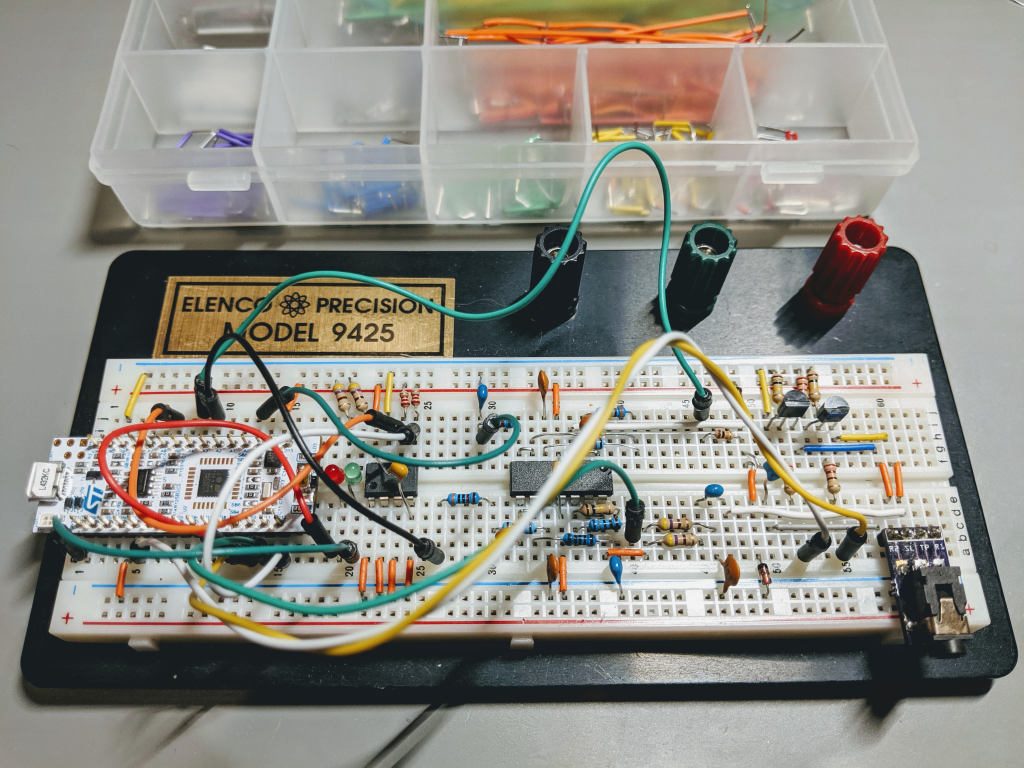
"The completely assembled NucleoTNC.\n",
"\n",
"Run through the [Power and Ground](#Power-and-Ground) diagnostics again.\n",
"\n",
"## Programming\n",
"\n",
"Programming is fairly simple. When you plug the Nucleo board into your computer, a new drive (mount point) will appear. Programming is done by simply copying the firmware file into this new mount point.\n",
"\n",
"Connect a USB cable from your computer to the Nucleo board. Be careful with the USB connector on the Nucleo board. When connected, it should enumerate a number of devices including a removable storage device and a serial port. For programming, we care about the removable storage device. On Windows this should appear as a drive letter. On Linux, this should be mounted somewhere like `/run/media/{USER}/NODE_L432KC`. And it should appear as a folder on your MacOS desktop.\n",
"\n",
"Download the `firmware.bin` file from the Mobilinkd GitHub site: https://github.com/mobilinkd/NucleoTNC/releases/tag/v1.0.0\n",
"\n",
"Copy the `firmware.bin` file to the Nucleo removable storage device. You should see the multi-color LED near the USB connector on the Nucleo flash while it is programming.\n",
"\n",
"That's all there is to it. The Nucleo TNC is now operational!\n",
"\n",
"\n",
"## Operation\n",
"\n",
"Before we begin -- a word of warning.\n",
"\n",
"----\n",
"\n",
"Do not tranmit RF near the Nucleo TNC. Use a dummy load when testing and use an external antenna that is mounted well away from the TNC when operating the TNC on the air. The long wires used in the assembly of the TNC, and the breadboard itself can act as antennas and will conduct RF energy into the TNC components and any equipment you have attached to it, including your computer. This may cause the TNC to misbehave and can potentially damage your equipment.\n",
" \n",
"Also, when not using a dummy load, it is your responsibility to avoid interfering with others and to announce your callsign. Use an unused channel, announce that you will be testing, perform the tests, then announce that you are done using the frequency.\n",
"
\n",
"\n",
"----\n",
"\n",
"The Nucleo TNC presents as a serial port and must be used with the following serial parameters:\n",
"\n",
" * 38400 baud, 8N1\n",
"\n",
"### Radio Configuration\n",
"\n",
"The configuration of your radio is important. If you are using an HT, go through the settings and turn everything off that can be turned off. Power saver settings and VOX must be turned off. If you are using a Baofeng or other cheap Chinese radio, turn off dual receive, squelch tail elimination, etc. In general, everything that can be turned off should be turned off.\n",
"\n",
"A note about cheap radios. Most of the cheap radios flooding the market as of late do not work well for general packet use. The problem is turn-around time -- the time it takes from turning off the transmitter to until the receiver can hear anything. A good radio has a turn-around time in the 10s of milliseconds. To be useful for packet radio, it cannot be much more than 100ms. Most of these cheap radios have turn-around times in the hundreds of milliseconds. Most Boafeng radios are in the 300ms range, which is unusable. You will miss the response from the remote end.\n",
"\n",
"These radios are adequate for running an APRS tracker, where you just want to beacon your position. The radio will probably miss the first digipeated response but you may not care about that.\n",
"\n",
"\n",
"### TNC Configuration\n",
"\n",
"For this step you will need a computer running Linux (preferrablY), MacOS or Windows.\n",
"\n",
"Plug the Nucleo board into the computer. Note the serial port address (/dev/tty device or COM port) assigned byt the operating system. On Linux this is often /dev/ttyACM0. On MacOS you should see /dev/cu.usbmodemXXXXX (where the X's are some number). On Windows it will be a COM port.\n",
"\n",
"#### Download Config App\n",
"\n",
"Download the Mobilinkd Config App for Linux/MacOS/Windows (TncConfigApp) for serial port.\n",
"\n",
"There is a Windows installer here: https://mobilinkd.s3.amazonaws.com/TncConfigApp-1.0.2-amd64.msi\n",
"\n",
"Note that on Windows, this installation may interfere with the RFCOMM version of the Mobilindk Config app for the Mobilinkd Bluetooth TNCs.\n",
"\n",
"Otherwise, for Linux and MacOS, download the source from our GitHub repository: https://github.com/mobilinkd/tnc1-python-config/archive/v1.0.1.tar.gz and follow the build instructions in the README.md file.\n",
"\n",
"\n",
"#### Connect to the TNC\n",
"\n",
"Run the Config App. Ensure you are running the *Serial Port Variant* of the app. Select the serial port from the dropdown menu and press \"Connect\".\n",
"\n",
"\n",
"\n",
"#### Check the TNC Information\n",
"\n",
"Once connected, go to the *TNC Information* screen and verify that you are connected to the breadboard TNC. If you do not see any information here, go to the [Testing and Troubleshooting](#Testing-and-Troubleshooting) section.\n",
"\n",
"\n",
"\n",
"#### Adjust the Audio Input Levels\n",
"\n",
"Connect the radio to the TNC. Tune to an unused frequency. Open the squelch on the radio.\n",
"\n",
"Go to the *Audio Input* section and configure the audio. An unused channel should have static noise on it. For an HT, the audio gain on the TNC should be set to 0, and the audio volume on the radio should be adjusted so that the right-most element in the bar graph flickers.\n",
"\n",
"If you are connecting the TNC to a mobile radio's data port and the output level is too low to cause the last LED to flicker, adjust the input gain until the desired level is reached. If it is still down a few bars, it should still work fine.\n",
"\n",
"If you do not see any activity in the bar graph, go to the [Testing and Troubleshooting](#Testing-and-Troubleshooting) section.\n",
"\n",
"The audio input twist should generally be set to 6 for an HT and most mobile radios. If connected to the discriminator input of a radio (no de-emphasis), set the twist to 0.\n",
"\n",
"\n",
"\n",
"#### Adjust the Audio Output Levels & PTT\n",
"\n",
"For this, you will need another radio (a receiver) tuned to the same frequency as the radio connected to the TNC. An RTL-SDR is inexpensive and works well for this.\n",
"\n",
"Go to the *Audio Output* section of the config app to configure the PTT style and output levels.\n",
"\n",
"Select the correct PTT signalling method. Mobile radios and hand-held radios with a Kenwood connector use Simplex PTT signalling. Most other hand-held radios use Multiplex PTT signalling. If you don't know, experiment to find the right one. Select the PTT signalling method and press the *Transmit* button. The radio should transmit a test tone. You should see the transmit indicator on the radio light up and you should hear the test tone in the other radio.\n",
"\n",
"If one PTT style does not work, try the other.\n",
"\n",
"To set output volume level, set the tone to 2200Hz and adjust the volume until the tone no longer increases in volume. For most hand-held radios this will be pretty low (in the 30s or 40s). Drop the volume level another 10%. \n",
"\n",
"In general, the output twist should be set to \"50\", the midway point.\n",
"\n",
"If you cannot trigger PTT or do not hear any audio, go to the [Testing and Troubleshooting](#Testing-and-Troubleshooting) section.\n",
"\n",
"\n",
"\n",
"#### Save Changes\n",
"\n",
"Once you are done configuring the TNC for your radio, go to the *Save Settings* section and press the \"Save Changes* button. This will write the configuration values to the board's EEPROM.\n",
"\n",
"We will then need to verify that the settings have been saved. It may be helpful to jot down all of the settings right now in case the settings are not retained.\n",
"\n",
"\n",
"Save Settings screen. Ignore the \"There are no unsaved changes\" text.\n",
"\n",
"To verify that the settings have been saved, press the \"Disconnect\" button on the top right.\n",
"\n",
"Unplug the USB cable from the TNC for a few seconds, then plug it back in. Using the Config App, reconnect to the TNC and verify that all of the level settings that you have just made have been retained.\n",
"\n",
"If the settings have not been retained, go to the [Testing and Troubleshooting](#Testing-and-Troubleshooting) section.\n",
"\n",
"### Using the TNC\n",
"\n",
"The TNC is now a fully operational KISS TNC. You can use APRS applications like Xastir on Linux, APRSIS32/CE on Windows, even \n",
"\n",
"\n",
"## Testing & Troubleshooting\n",
"\n",
"The most common cause of problems with any such project is that a part is not placed correctly, either in the wrong breadboard location or reversed if polarized, or the miswired. Review all of the build steps. Verify component and wiring placement.\n",
"\n",
"Please joing the [Mobilindk Community](https://groups.io/g/mobilinkd) on groups.io tfor help troubleshooting and using your Nucleo TNC.\n",
"\n",
"We are going to walk through the fault tree to narrow down the location of the problem.\n",
"\n",
"The Nucleo32 board has three LEDs on it which will be used for diagnostics.\n",
"\n",
" * USB communication (LD1)\n",
" * Power LED (LD2)\n",
" * User LED (LD3)\n",
"\n",
"The first step is always to check power and ground.\n",
"\n",
"### Power and Ground Troubleshooting\n",
"\n",
"**Does the board have power?**\n",
"\n",
"Refer to the board layout here: https://os.mbed.com/platforms/ST-Nucleo-L432KC/\n",
"\n",
"Run through the [Power and Ground](#Power-and-Ground) diagnostics again.\n",
"\n",
"Given the number of times we ran through this process in the build, there should be no problem with the power and ground rails. If there is, it is generally because something has shorted out. Check the two areas of concern in the input and output circuitry.\n",
"\n",
"Verify that your USB port is capable of delivering 500mA.\n",
"Verify that your USB cable is still in good condition. If in doubt, try another one.\n",
"Verify that the USB connector on the Nucleo board has not been damaged. If it has, you will need to repair or replace the Nucleo board.\n",
"\n",
"### Nucleo Connection\n",
"\n",
"**Is the Nucleo board recognized by the OS**\n",
"\n",
"This section assumes that you have verified that power and ground are OK.\n",
"\n",
"The Nucleo board, when connected to a computer via USB, should enumerate a number of ports on the host machine:\n",
"\n",
" * A mass storage device which is mounted by the operating system\n",
" * This will mount as a drive letter on Windows\n",
" * This will appear as a drive on the MacOS desktop\n",
" * This should be mounted at/run/media/{USER}/NODE_L432KC on modern Linux systems, and appear as a mount point in the file explorer.\n",
" * A serial port\n",
" * This will appear as a COM port on Windows.\n",
" * This will appear as /dev/cu.usbmodemXXXXX on MacOS.\n",
" * This will appear as /dev/ttyACMx on Linux.\n",
" * An MBED or ST/Link progamming interface\n",
" * This is not used by this project.\n",
"\n",
"If the Nucleo board fails to enumerate all of these devices, you may be using a \"power only\" USB cable. Use your DMM to check the connectivity on the USB cable data lines. Or try another cable.\n",
"\n",
"I have not run into any problems with drivers on any of the operating systems tested.\n",
"\n",
"### Firmware Programming\n",
"\n",
"This section assumes that you have verified that the Nucleo device is enumerating properly and the Nucleo's mass storage device is mounted.\n",
"\n",
"Programming simply involves copying the firmware binary to the mass storage device. You will see the multi-color LED (LD1) on the Nucleo board flash while it programs.\n",
"\n",
"Linux may report that the device is full if you have programmed it once already. The solution here is to disconnect the USB cable from the Nucleo board and plug it back in. If you have permissions issues on Linux, you may need to add your user to the \"plugdev\" group use `sudo` to copy the file to the Nucleo board.\n",
"\n",
"There are few potential issues with programming. The MBED site is the best place for help on mounting an programming the Nucleo board.\n",
"\n",
"\n",
"### Audio Input\n",
"\n",
"You will need an oscilloscope to fully test the audio input section.\n",
"\n",
"This section assumes that you have verified the power settings, that the Nucleo connections are OK, that the firmware has been programmed, and that you can connect to the TNC from the Mobilinkd Config App.\n",
"\n",
"#### DC Offset\n",
"\n",
"Disconnect the radio from the TNC. We will be using the Mobilinkd Config App to charaterize the DC offset by changing the audio input gain.\n",
"\n",
" * Connect the config app to the TNC and go to the *Audio Input* settings.\n",
" * Set the audio input gain to 0. Use a DMM to verify that the voltage at *g49* is 1.65V.\n",
" * Set the audio input gain to 1. Use a DMM to verify that the voltage at *g49* is 0.825V.\n",
" * Set the audio input gain to 2. Use a DMM to verify that the voltage at *g49* is 0.41V.\n",
" * Set the audio input gain to 3. Use a DMM to verify that the voltage at *g49* is 0.2V.\n",
" * Set the audio input gain to 4. Use a DMM to verify that the voltage at *g49* is 0.1V.\n",
"\n",
"If the voltage is not 1.65V when the gain is set to 0, check the wiring of the cable from *j8* to *j46* and the 10kΩ resistor from *h46* to *h49*. Check the output of pin A4 on the Nucleo board. Each of these points should be at 1.65V. Fix any wiring problems. Verify that the Schottky diodes are oriented properly. Use the diode test function on the DMM to verify that the diodes have not been damaged.\n",
"\n",
"When changing the input gain, the measured voltage should roughly halve at each step. The voltages should change if the TNC is programmed and the config app is communicating with the TNC. If the voltages do not change, the TNC is not programmed or the config app is not communicating with the TNC.\n",
"\n",
"#### Audio Cable\n",
"\n",
"You will need an oscilloscope to check the audio input.\n",
"\n",
"Connect the audio cable to the radio only.\n",
"Disconnect it from the TNC if it is connected.\n",
"Turn on the radio.\n",
"Using the oscilloscope, verify that the radio's audio output signal is present at the the cable tip\n",
"\n",
" * Measure across the tip and sleeve of the connector (the sleeve is ground). If an audio signal is not present:\n",
" * turn up the volume on the radio\n",
" * use a DMM to check continuity on the cable\n",
" * verify that the cable is properly seated in the radio\n",
" * verify that the cable pinout is correct\n",
"\n",
"#### Raw Audio Input\n",
"\n",
"Connect the cable to the TNC.\n",
"\n",
"With the oscilloscope, verify that you see an audio signal at:\n",
"\n",
" * The 3.5mm connector tip *c58*.\n",
" * The capacitor at *e50* and *g49*\n",
" * The wire from *i49* to *i36* -- this is the input to the audio input buffer.\n",
"\n",
"Check the wiring along the way.\n",
"\n",
"If the audio output is being clipped at -0.3V and/or +3.6V, reduce the audio volume on the radio.\n",
"\n",
"#### Buffered Audio Input\n",
"\n",
"This assumed that the raw audio output is good up to the audio input buffer at *i36*.\n",
"\n",
"With the oscilloscope, verify that you see an audio signal at:\n",
"\n",
" * The jumper at *g37* to *g38*.\n",
"\n",
"Verify that the resistor from *g41* to *g32* is not shorted to the jumper at *g37* to *g38*.\n",
"Verify that conenction power and ground connections of the op amp.\n",
"\n",
"#### Filtered Audio Input\n",
"\n",
"This assumed that the buffered audio output is good up to the jumper at *g37* to *g38*.\n",
"\n",
"Filtered audio output should appear at the resistor lead at *i29*.\n",
"\n",
"Verify all of the connections in the [Audio Input](Audio Input) section.\n",
"\n",
"### Saving Settings\n",
"\n",
"To verify that settings are being saved:\n",
"\n",
" * Connect the Nucleo board via USB to turn it on.\n",
" * Start the configuration app.\n",
" * Connect to the TNC.\n",
" * Change a setting, such as the input twist.\n",
" * Go to the \"Save Settings\" page.\n",
" * Click the \"Save Changes\" button. This should write the changes to EEPROM.\n",
" * Press the \"Disconnect\" button.\n",
" * Disconnect the USB cable momentarily, then reconnect it. This will reset the board and cause the TNC to read the configuration from EEPROM.\n",
" * In the configuration app, connect to the TNC.\n",
" * Verify that the setting you change has been retained.\n",
"\n",
"If the above test fails:\n",
"\n",
" * Using a DMM, check that the EEPROM has 3.3V power at *f21*.\n",
" * Using a DMM, check that the EEPROM is pulled up to 3.3V at *f23* and *f24*.\n",
" * Using a DMM, check that the WP pin at *f22* is pulled low (0V).\n",
" * Using a DMM, check that all of the address lines and ground line, *e21, e22, e23, e24* are connected to ground.\n",
" * Verify a wire connects from *a15* to *i24* for I2C SDA on the EEPROM.\n",
" * Verify a wire connects from *j6* to *i23* for I2C SCL on the EEPROM.\n",
"\n",
"If this looks OK, we will need to probe the I2C bus.\n",
"\n",
" * Use an oscilloscope to probe the I2C lines at *g23* (CH1/SCL) and *g24* (CH2/SDA).\n",
" * Use a logic analyzer to probe the data on the I2C bus. Refer to the data sheet for the expected data.\n",
"\n",
"Sigrok software can be used to decode the I2C data and even the higher-level 24Cxx EEPROM read/write protocol."
]
},
{
"cell_type": "code",
"execution_count": null,
"metadata": {},
"outputs": [],
"source": []
}
],
"metadata": {
"kernelspec": {
"display_name": "Python 3",
"language": "python",
"name": "python3"
},
"language_info": {
"codemirror_mode": {
"name": "ipython",
"version": 3
},
"file_extension": ".py",
"mimetype": "text/x-python",
"name": "python",
"nbconvert_exporter": "python",
"pygments_lexer": "ipython3",
"version": "3.7.9"
}
},
"nbformat": 4,
"nbformat_minor": 2
}