# Blender project of the Game Boy CPU
I don't know how to use Blender, I just watched a turorial on how to import a
VLSI layout into Blender to render it in 3D.
This is the tutorial I used:
Here is the Electric VLSI project that contains the layout:
I put this out here, so maybe someone else can help me improve it and maybe make
some flying animations.
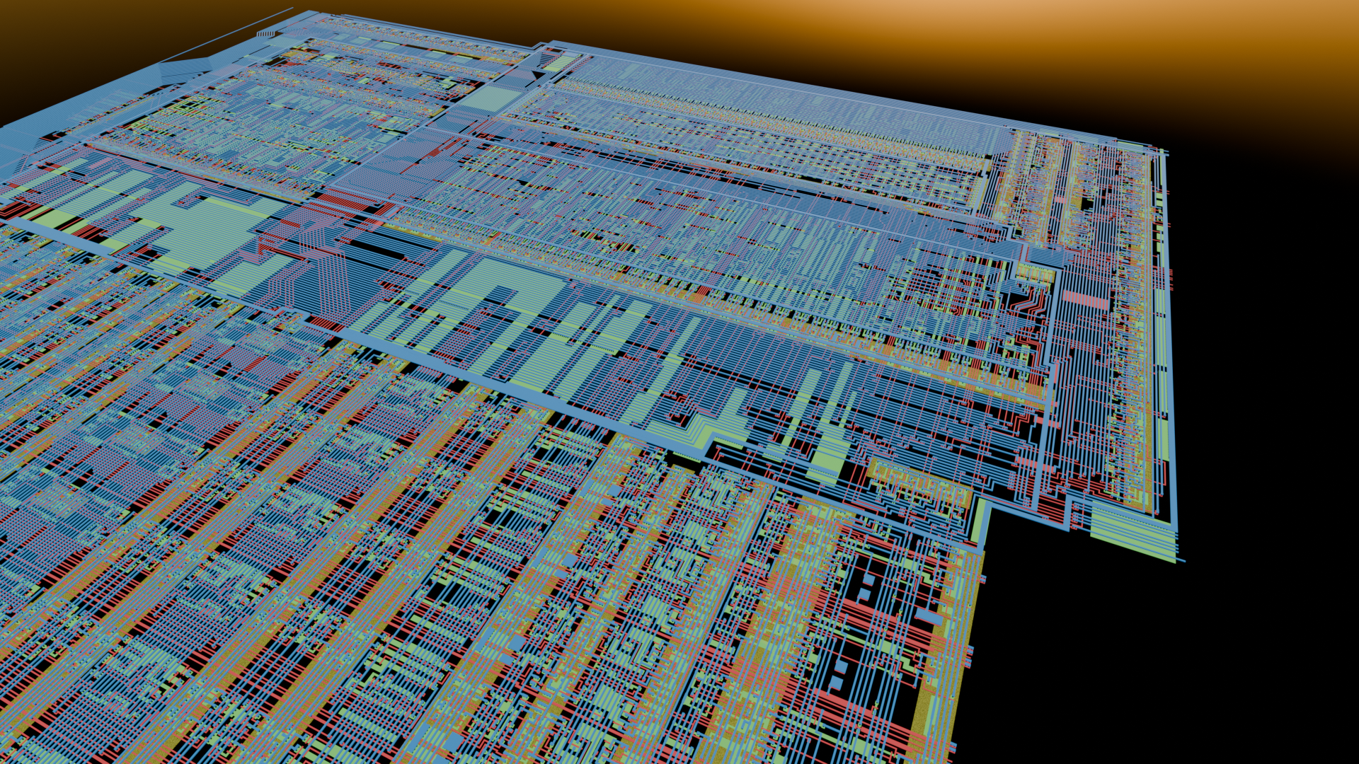
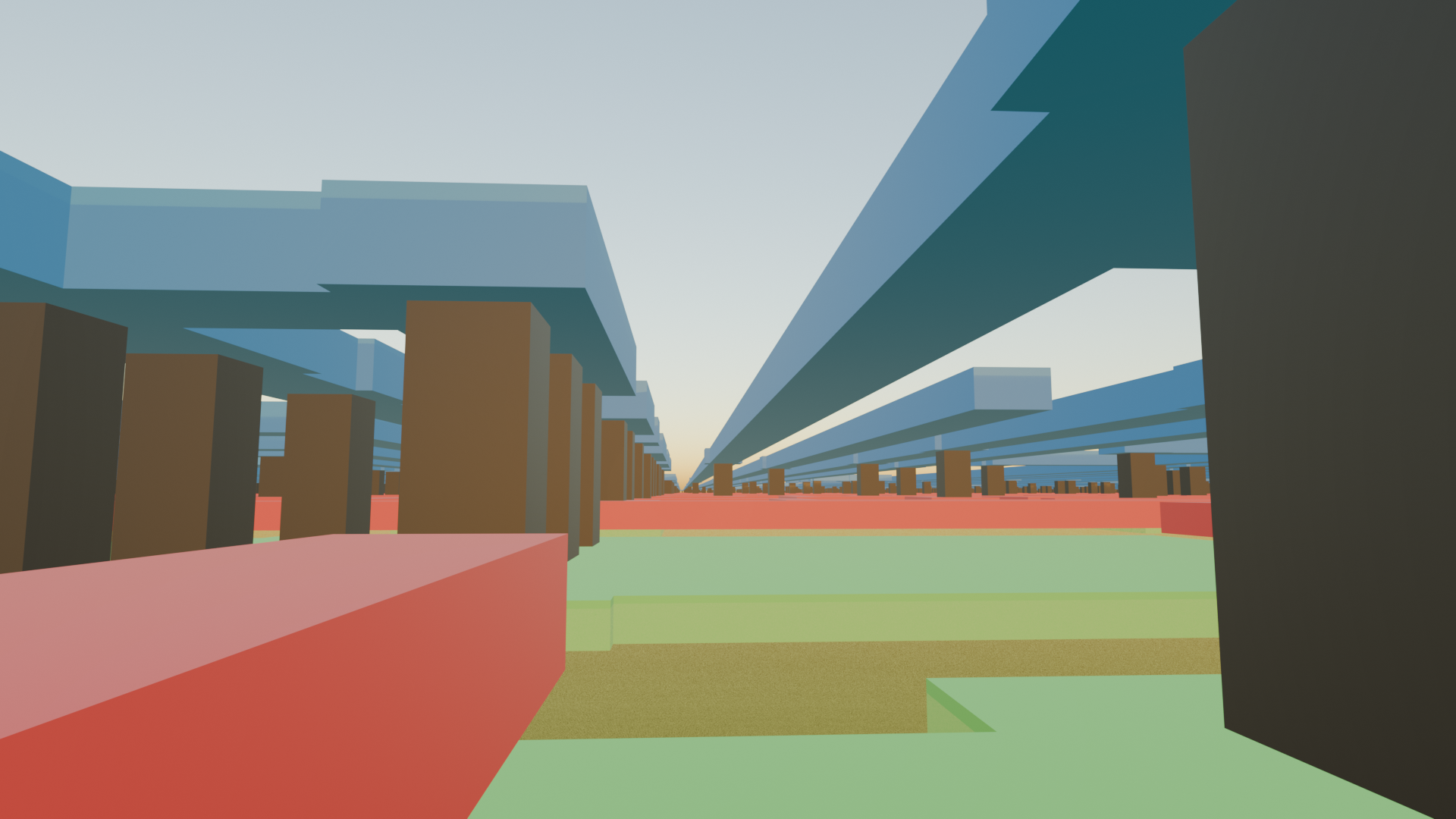
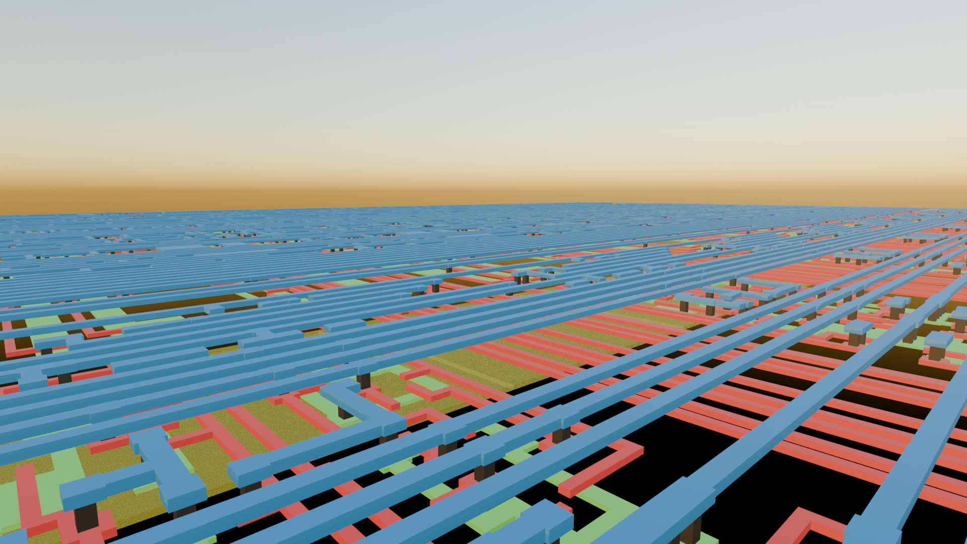
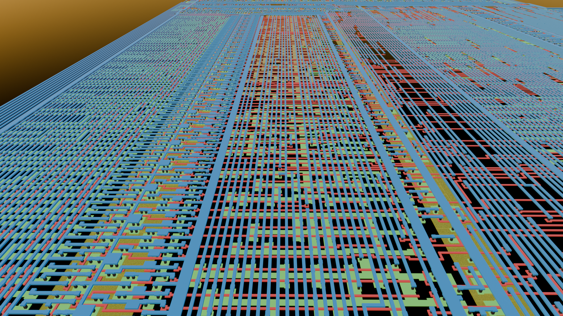
Here are some renderings:
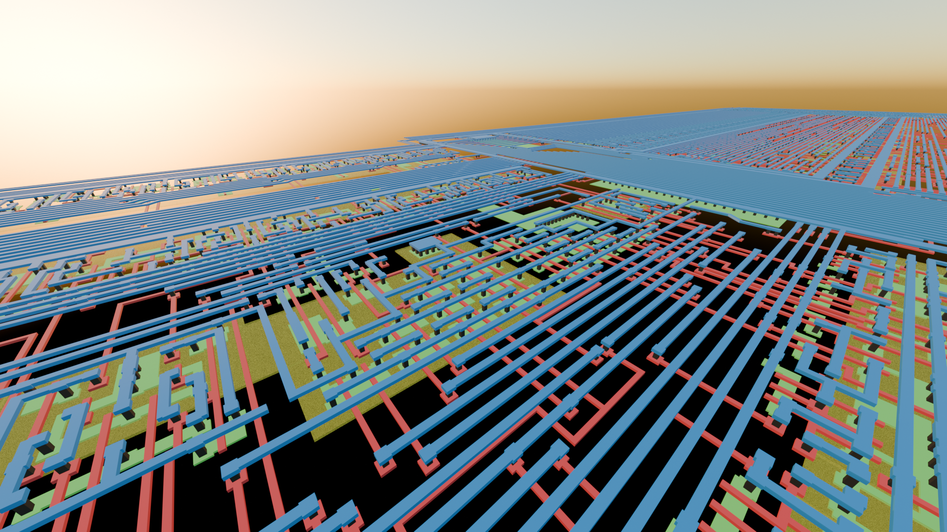
I placed the poly layer directly ontop of the active areas without a gap, because
otherwise you would see the poly cuts peak out underneath the poly. The technology
I used in Electric uses the same layer for poly and active cuts. So when I make the
cuts shorter, then there would be a gap between the active cuts and the active
areas. I don't know if this can be done in Blender, so that the cuts are
shortened only where they're above poly.