# Details Wiring
## Actuator Module Wiring
*Electrical connection actuator modules*
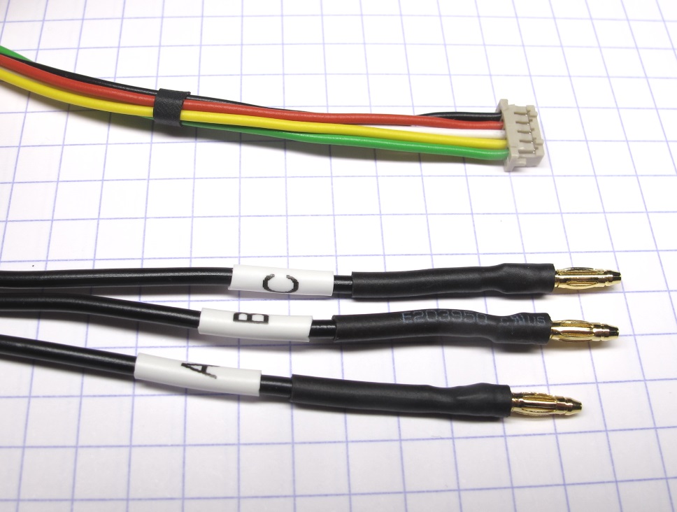
* the electrical interface of the actuator modules consists of a 5 pole encoder wire and 3 motor phase wires
* for the encoder wires we use [0,14 mm² Kabeltronik wires](details_components.md#kabeltronik-encoder-wires) with a [5 pole Hirose DF13 connector](details_components.md#hirose-df13-sockets)
* for crimping the wires you will need the [DF13 crimp terminals](details_components.md#hirose-df13-crimp-terminals) and the [Hirose DF13 crimp tool](details_components.md#hirose-crimp-tool)
* the color code and pin assignment is documented below
* for the motor phase wires we use [0,50 mm² Kabeltronik wires](details_components.md#motor-phase-wires) with [2mm Reely gold connectors](details_components.md#motor-phase-connectors)
* we measure the wire length of the actuator modules from the surface where the wires exit the shell to the connector interface
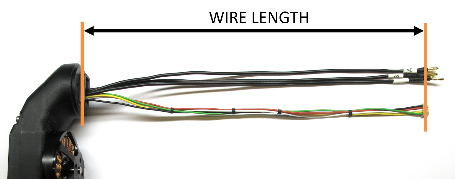
*Wire length actuator modules*
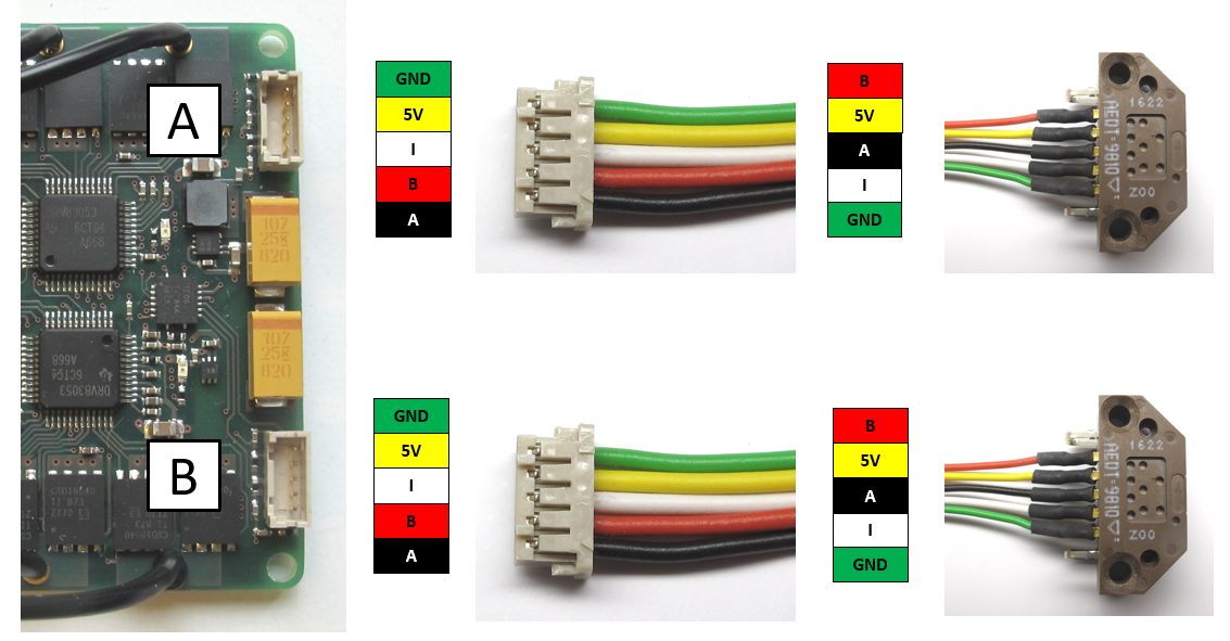
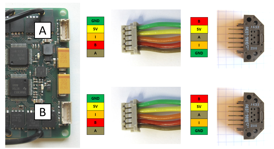
*Encoder wiring with Kabeltronik wires*
## Micro Driver Board Wiring
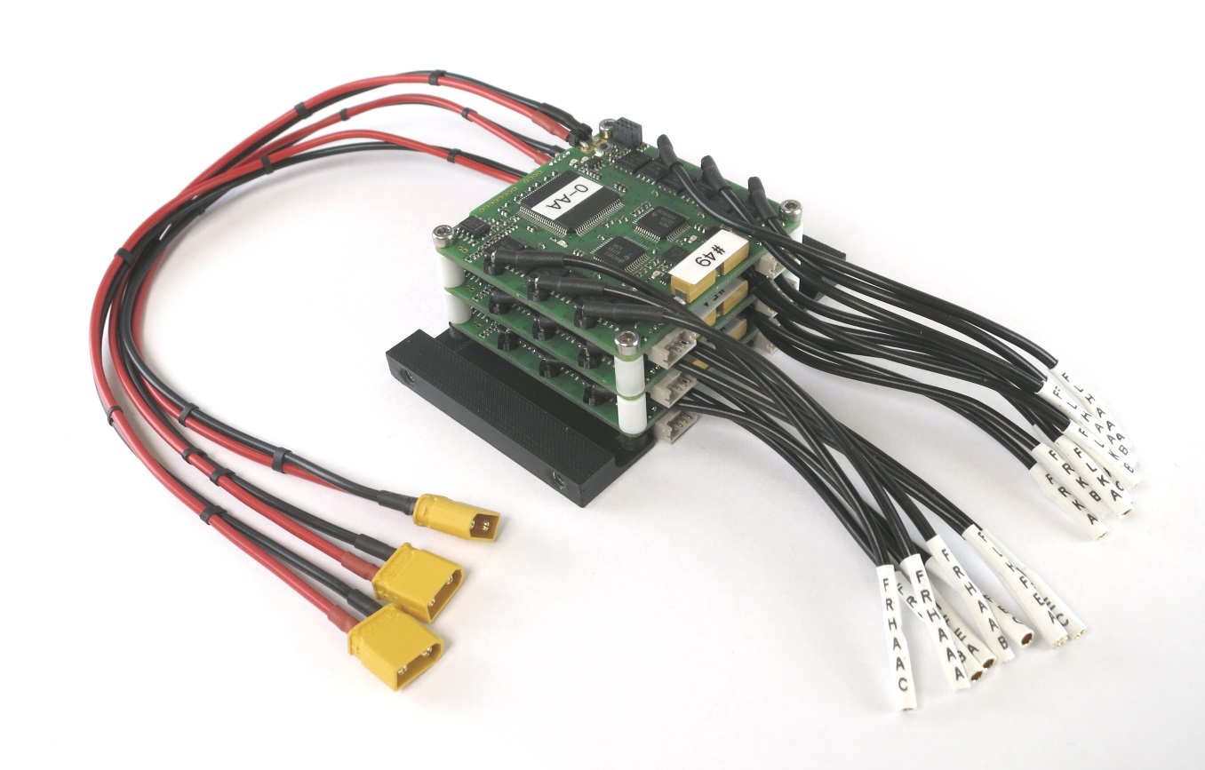
*Fully assembled micro driver stack*
* we use [right angle pin headers](details_components.md#right-angle-pin-headers) for connecting the motor phase and power wires to the micro driver board
* for the motor phase wires we use [0,50 mm² Kabeltronik wires](details_components.md#motor-phase-wires) with [2mm Reely gold connectors](details_components.md#motor-phase-connectors)
* for the power supply wires wie use [0,50 mm² Kabeltronik wires](details_components.md#motor-phase-wires) with [XT30 power connectors](details_components.md#power-connectors)
* we measure the wire length of the electronics from the edge of the electronis board to the connector interface.
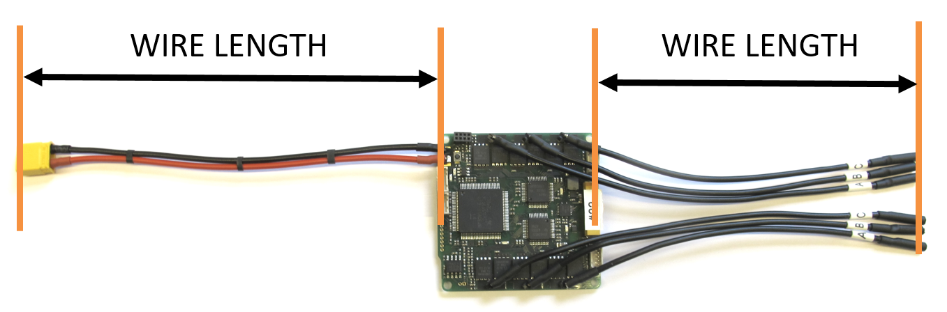
*Wire length electronics boards*
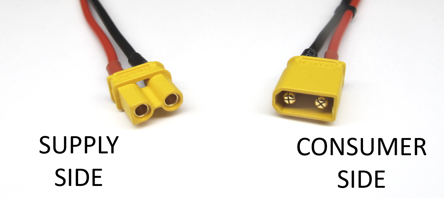
*Convention power connectors*
---
## SPI Wires
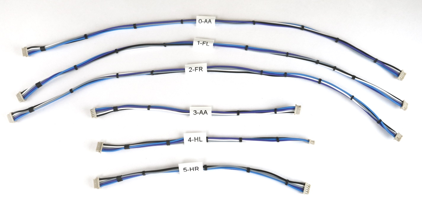
* for the SPI connections between the master board and the micro driver boards we use [0,14 mm² Kabeltronik wires](details_components.md#kabeltronik-encoder-wires) with two [5 pole Hirose DF13 connectors](details_components.md#hirose-df13-sockets)
* for crimping the wires you will need the [DF13 crimp terminals](details_components.md#hirose-df13-crimp-terminals) and the [Hirose DF13 crimp tool](details_components.md#hirose-crimp-tool)
* the color code and pin assignment is documented below
* the spi bus operates at high frequencies - keep the wires short
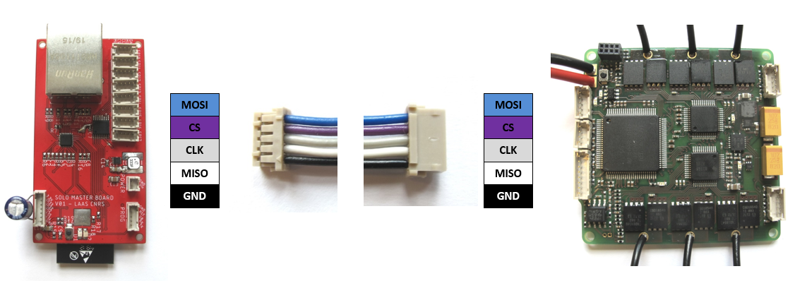
*SPI bus connection between the master board and the micro driver boards*
---
## IMU Wire
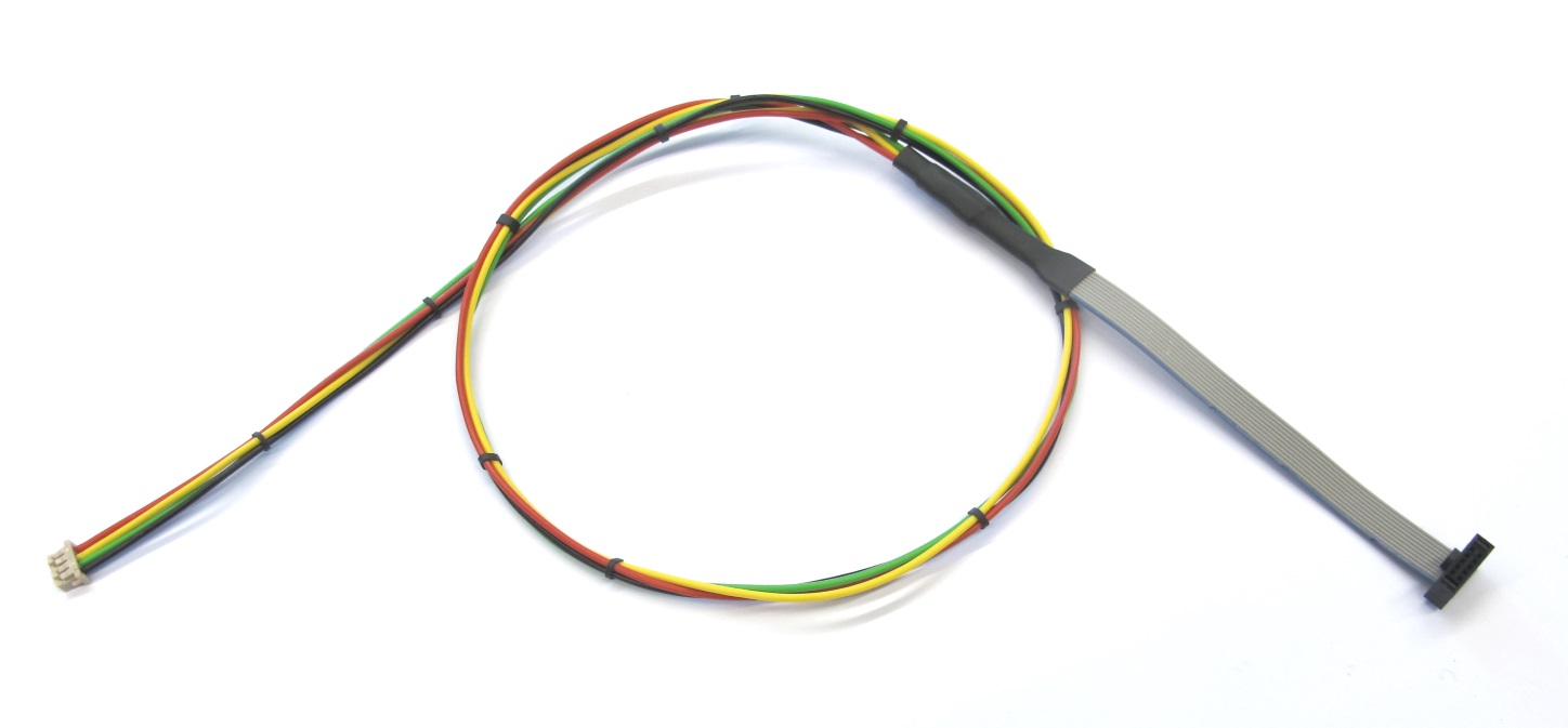
*Wire for Inertia Measurement Unit*
* for connecting the inertia measurement unit to the master board we use a [ribbon cable with a 10 pin rectangular connector](details_components.md#imu-cable) and extension wires with a [4 pin Hirose connector](details_components.md#hirose-df13-sockets)
* the pin assignment is documented here: [Master Board Wiring](https://github.com/open-dynamic-robot-initiative/master-board/blob/master/documentation/masterboard_wiring.md#imu)
---
## Robot Interface Wire
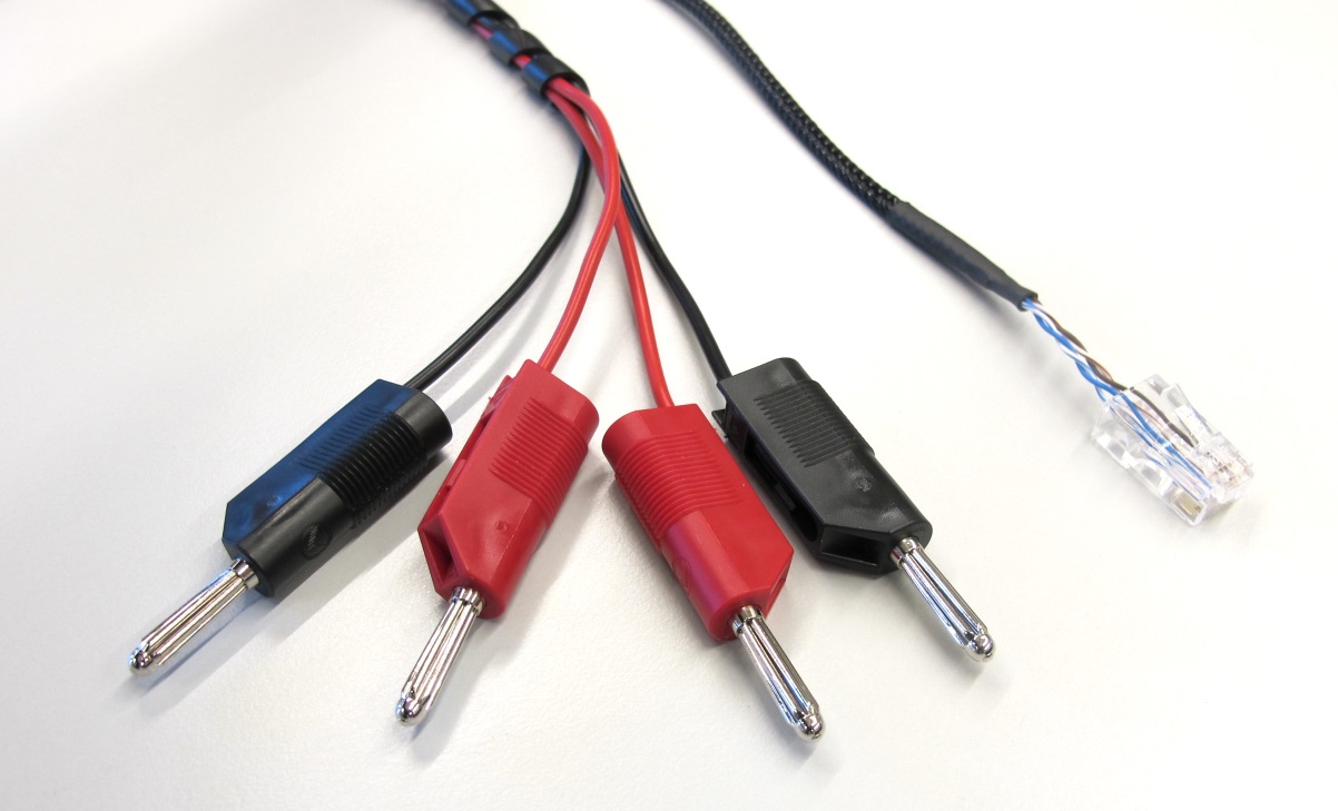
*Robot Interface Wire - Supply Side*
* for powering the robots we use [1 mm² Kabeltronik wires](details_components.md#power-connectors-and-cable) with [4mm power connectors](details_components.md#power-connectors-and-cable) on the supply side
* to reduce the diameter and stiffness of the wire we use a self-made 4 pole ethernet wire
* the color code and pin assignment is documented below - the ethernet connectors are identical on both sides
* for crimping the [ethernet connectors](details_components.md#ethernet-connector) you will need the corresponding [crimp tool](details_components.md#crimp-tool-ethernet-connector)
* you can use a standard ethernet wire instead
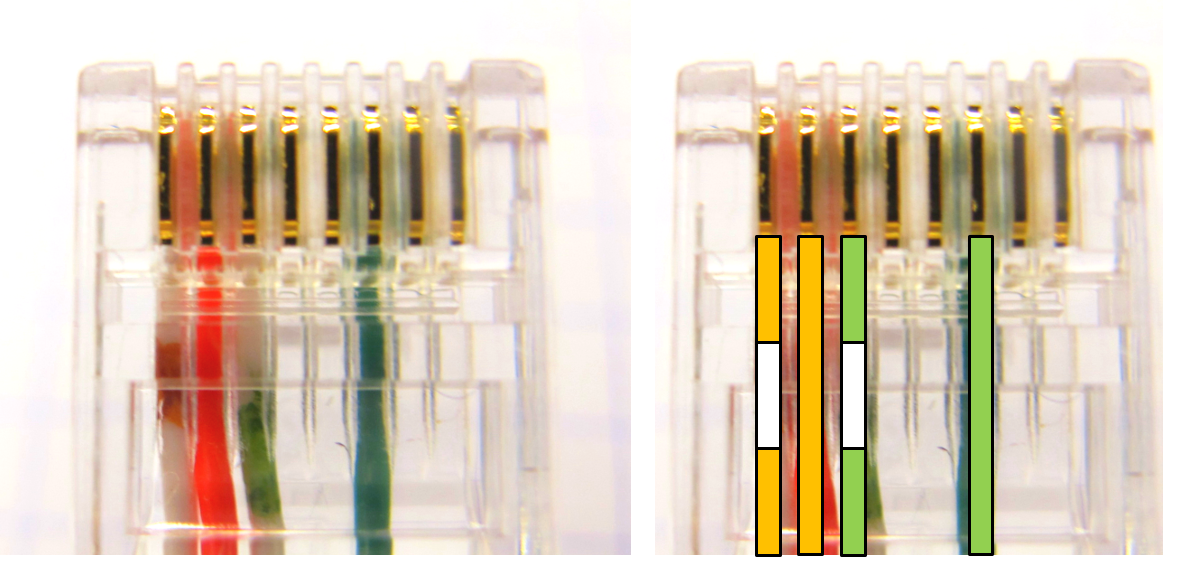
*Self-made ethernet wire with 4 connections*
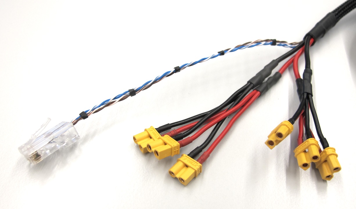
*Robot Interface Wire - Robot Side*
* for powering the robots we use [1 mm² Kabeltronik wires](details_components.md#power-connectors-and-cable) with [XT30 power connectors](details_components.md#power-connectors) on the robot side
*Convention power connectors*
---
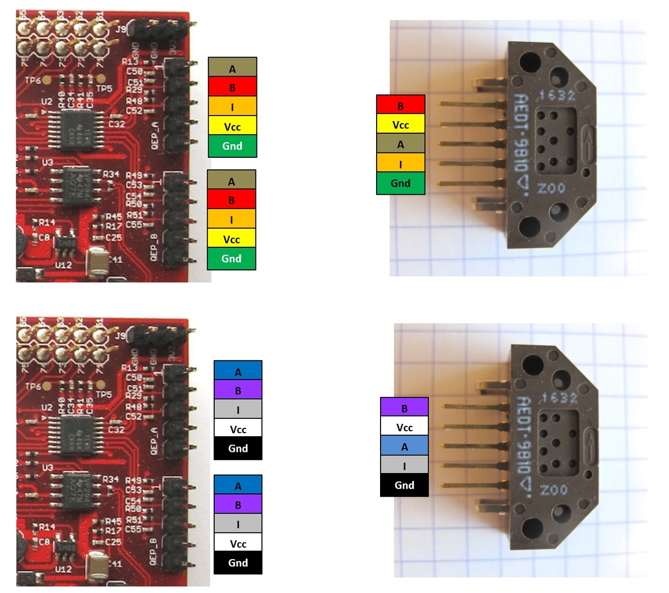
## Wiring Ribbon Cables- Encoder to Micro Driver Electronics
*Encoder wiring with ribbon cables*
---
## Wiring Ribbon Cables - Encoder to TI Launchpad
*Encoder wiring with ribbon cables*
---
## Wiring - Foot Sensor
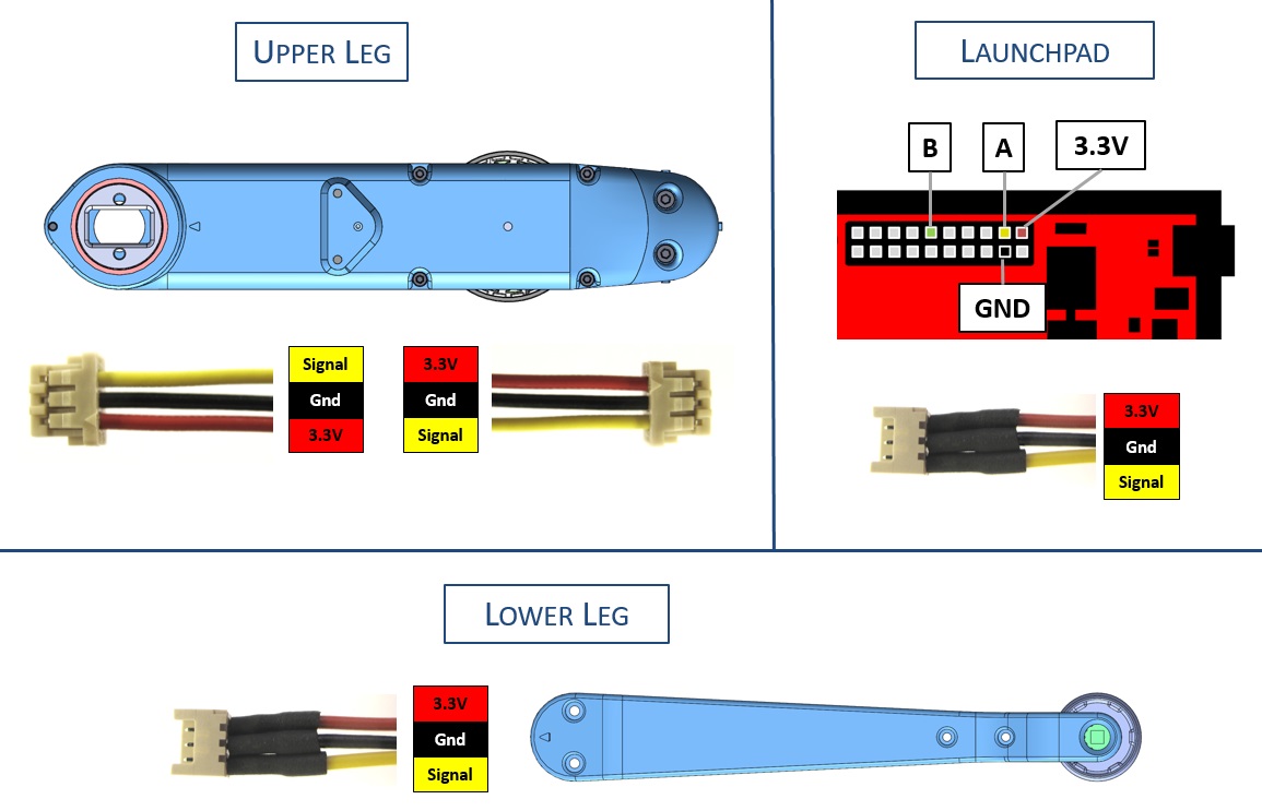
*Foot sensor wiring*
---
## CAN Connector Wiring
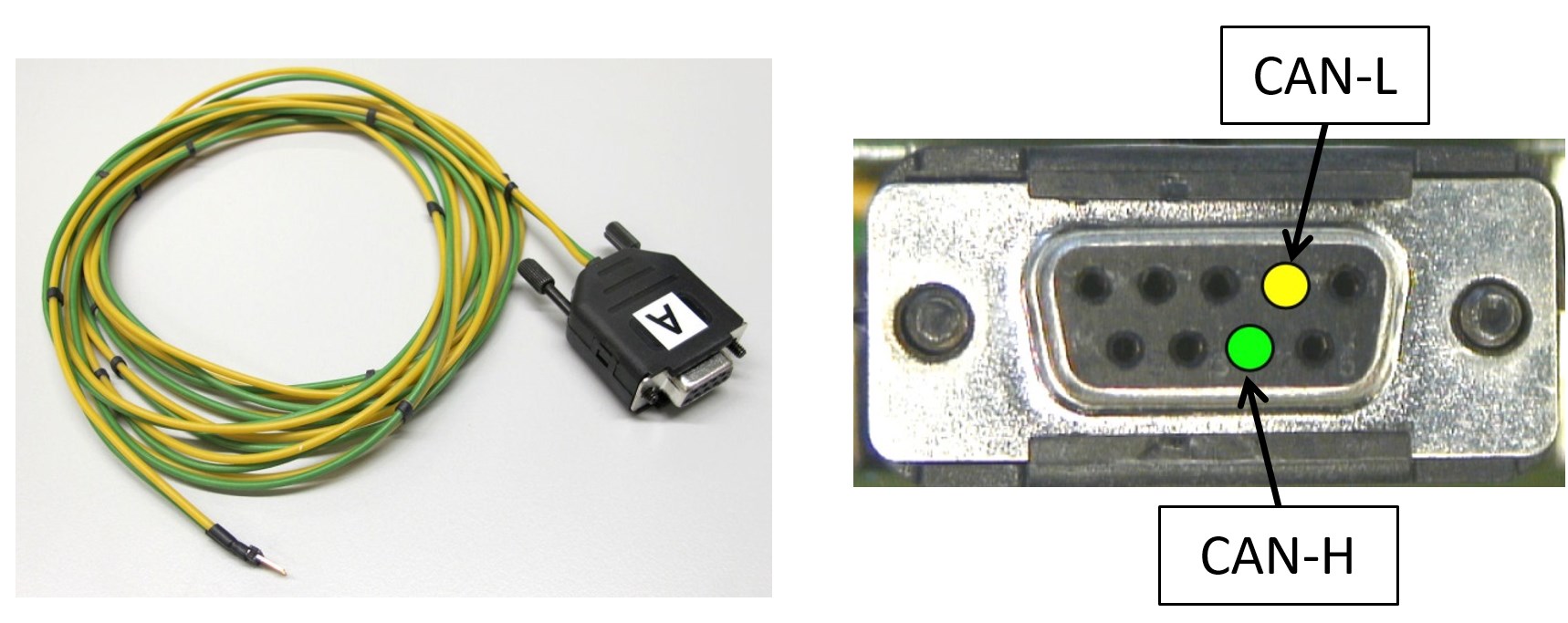
*CAN connector wiring*
* for communicating with the Texas Instruments Evaluation Boards we use a 2 pole wire with a [9 pin D-sub connector](details_components.md#can-connector)
* on the computer side we use a [PEAK PCI Express CAN card](details_components.md#can-card)
---
## More Information
[Open Dynamic Robot Initiative - Webpage](https://open-dynamic-robot-initiative.github.io)
[Open Dynamic Robot Initiative - YouTube Channel](https://www.youtube.com/channel/UCx32JW2oIrax47Gjq8zNI-w)
[Open Dynamic Robot Initiative - Forum](https://odri.discourse.group/categories)
[Open Dynamic Robot Initiative - Paper](https://arxiv.org/pdf/1910.00093.pdf)
[Hardware Overview](../../README.md#open-robot-actuator-hardware)
[Software Overview](https://github.com/open-dynamic-robot-initiative/open-dynamic-robot-initiative.github.io/wiki)
[Back to Electronics](../README.md)
## Authors
Felix Grimminger
## License
BSD 3-Clause License
## Copyright
Copyright (c) 2019-2020, Max Planck Gesellschaft and New York University