# Leg Test Stand v2

## Description
This teststand allows us to evaluate the performance of a single 2dof leg with external sensors.
The teststand has a linear guided vertical degree of freedom and a carriage that holds the leg and the motor driver electronics. The ground reaction forces are measured with a 6 axis force-torque-sensor and are transmitted to the control pc at 1kHz. The vertical position of the carriage is measured with an analog string potentiometer. The test stand can be equipped with a pull-up-motor module for automated resetting to the initial position for machine learning experiments.
* This is an updated version of the [Leg Test Stand v1](../leg_test_stand_v1#leg-test-stand-v1)
* The details of the 2dof leg are described here: [Leg 2dof v2](../leg_2dof_v2/README.md#leg-2dof-v2)
* the details of the custom electronics are described here:
* [Details Master Board](https://github.com/open-dynamic-robot-initiative/master-board#master-board)
* [Details Micro Driver Board](../../electronics/micro_driver_electronics/README.md#micro-driver-electronics)
## Details Leg Test Stand

*Leg Test Stand v2 cad model*
* vertical range: 85cm
* pull-force height sensor about 2N
* weight carriage with electronics and 2dof leg: 713g
* 24V power supply and ethernet connection

*Carriage with 2dof leg and custom motor driver electronics - weight: 713g*
## Electronics
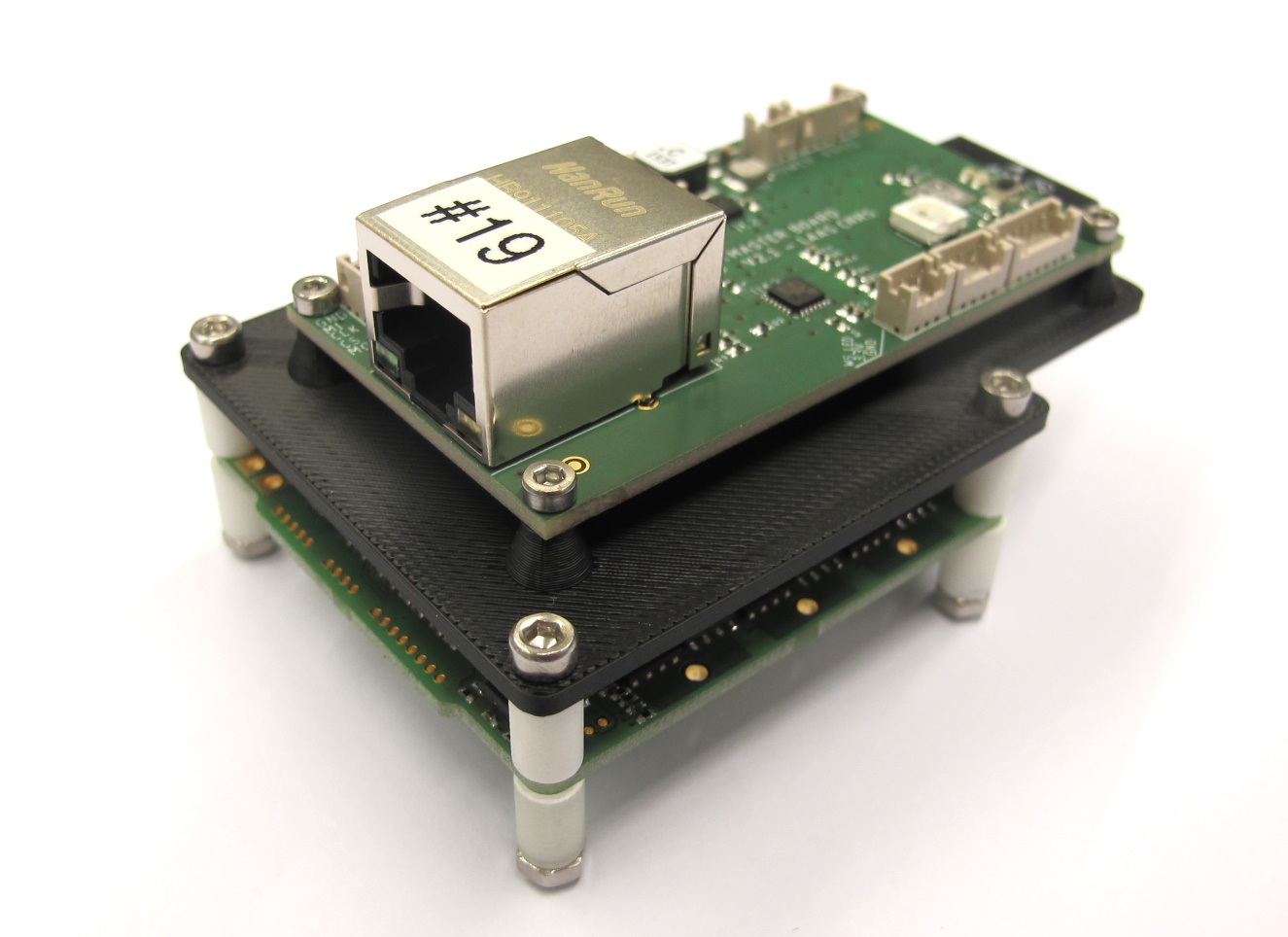
*Electronics Stack - weight: 45g*
### Master Board

*Master Board v2 - weight: 19g each*
* [Master Board Documentation](https://github.com/open-dynamic-robot-initiative/master-board#master-board)
### Micro Driver Electronics
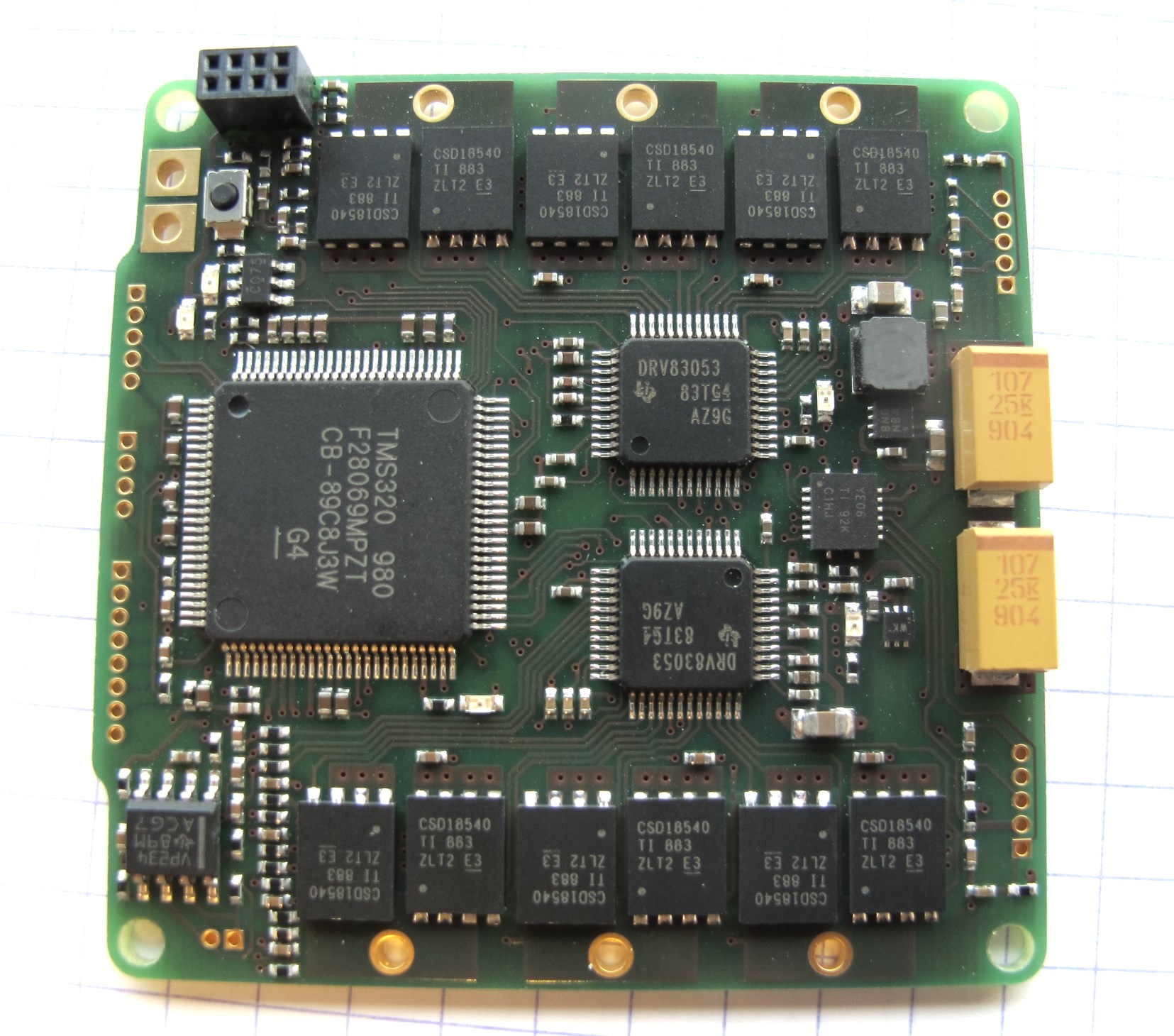
*Micro Driver Electronics - weight: 13g*
* the micro driver board controls 2 brushless motors
* [Micro Driver Board Documentation](../../electronics/micro_driver_electronics/README.md#micro-driver-electronics)
### Height Sensor

*Waycon string potentiometer*
* Waycon LX-PA-40 string potentiometer
* measurement range 1000mm
* [Waycon Webpage](https://www.waycon.biz)
* [Waycon String Potentiometer Datasheet](https://www.waycon.biz/fileadmin/draw-wire-sensors/Draw-Wire-Sensor-LX.pdf)
* ordering information [below](#bill-of-materials---leg-test-stand-v2)
### Force Torque Sensor

*ATI Mini-40-E force-torque-sensor*
* 6 axis force-torque sensor
* ATI Mini-40-E with SI-40-2 Calibration
* NetBA Interface Box required
* Ethernet communication with control pc
* [ATI Mini-40 Product Page](https://www.ati-ia.com/products/ft/ft_models.aspx?id=Mini40)
* [ATI Mini-40-E Technical Drawing](https://www.ati-ia.com/app_content/Documents/9230-05-1314.auto.pdf)
* [NetBA Interface Box Technical Drawing](https://www.ati-ia.com/app_content/documents/9230-05-1327.auto.pdf)
* ordering information [below](#bill-of-materials---leg-test-stand-v2)
## Off-the-shelf Components
### Linear Guide
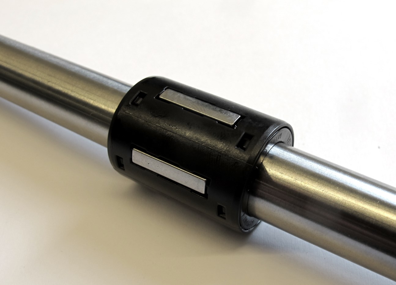
*Linear ball bearing and linear motion rod*
* Linear ball bearings: KB-1
* Rod diameter 14mm
* Linear motion rods: Precision Stainless Steel Rods X46 14h6 x 1000mm
* ordering information [below](#bill-of-materials---leg-test-stand-v2)
### Aluminum profiles

*Item aluminum profile*
* Item aluminum profiles - Size 8 - 40mm x 40mm
* required profile length: 2,7m
* segment lengths: 120cm / 70cm / 50cm / 30cm
* ordering information [below](#bill-of-materials---leg-test-stand-v2)
### Angle brackets

*Item 90 degree angle bracket 40mm*
* 90 degree 40mm angle brackets
* ordering information [below](#bill-of-materials---leg-test-stand-v2)
### End caps

*Item end caps*
* end caps - size 8
* ordering information [below](#bill-of-materials---leg-test-stand-v2)
### T-slot nuts

*Item M5 t-slot nuts*
* T-slot nuts M5
* ordering information [below](#bill-of-materials---leg-test-stand-v2)
### Steel Pins
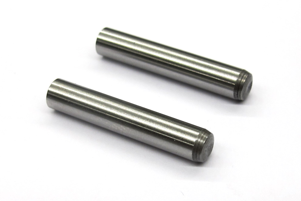
*5mm Steel Pins*
* Steel Pins - 5mm x 28mm
* ordering information [below](#bill-of-materials---leg-test-stand-v2)
### Carbon-Fiber Tube

*Carbon-fiber tube*
* O.D. 6mm / I.D. 4mm / Length 30cm
* for wire management
* ordering information [below](#bill-of-materials---leg-test-stand-v2)
---
## 3D Printed Parts

`The recommended printing direction for all the parts below is the positive z direction of the stl files.`
All the STL files for 3d printing the Leg Test Stand can be found here: [STL Files Leg Test Stand](stl_files).
---

* [Carriage - STL file](stl_files/carriage.STL)
* print on FDM or SLS printer
---

* [Master Board Support - STL file](stl_files/master_board_support.STL)
* print on FDM or SLS printer
---

* [Spacer Micro Driver Stack - STL file](stl_files/spacer_micro_driver_stack.STL)
* print on SLA, Multijet or Polyjet printer
---

* [Linear Bearing Cover - STL file](stl_files/linear_bearing_cover.STL)
* print on FDM or SLS printer
---

* [Adjustment Sleeve - STL file](stl_files/adjustment_sleeve.STL)
* print on SLA, Multijet or Polyjet printer
---

* [Linear Motion Rod Attachment - STL file](stl_files/linear_motion_rod_attachment.STL)
* print on FDM or SLS printer
---
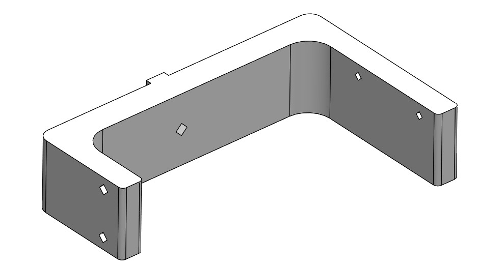
* [String Potentiometer and Pullup Motor Mount - STL file](stl_files/string_potentiometer_pullup_motor_mount.STL)
* print on FDM or SLS printer
---

* [Pulley Pullup Module - STL file](stl_files/pulley_pull_up_module.STL)
* for pullup motor / optional
* print on FDM or SLS printer
---

* [ATI Sensor Top Plate - STL file](stl_files/ati_sensor_top_plate.STL)
* print on FDM or SLS printer
---

* [ATI Sensor Bottom Plate - STL file](stl_files/ati_sensor_bottom_plate.STL)
* print on FDM or SLS printer
---

* [Motor Driver Electronics Attachment - STL file](stl_files/motor_driver_electronics_attachment.STL)
* for pullup motor electronics / optional
* print on FDM or SLS printer
---

* [Stopper Attachment - STL file](stl_files/stopper_attachment.STL)
* print on FDM or SLS printer
---

* [Stopper Wing - STL file](stl_files/stopper_wing.STL)
* print on FDM or SLS printer
---
## Bill of Materials - Leg Test Stand v2

| Description | Quantity | Ordering Information | Comments |
| --- | --- | --- | --- |
|2DOF Leg |1|[2DOF Leg Documentation](../leg_2dof_v2/README.md#leg-2dof-v2)|Custom assembly|
|Master Board|1|[Master Board Documentation](https://github.com/open-dynamic-robot-initiative/master-board#master-board)|Custom electronics|
|Micro Driver Board|1|[Micro Driver Board Documentation](../../electronics/micro_driver_electronics/README.md#micro-driver-electronics)|Custom electronics|
|String Potentiometer|1|Waycon LX-PA-40
[Waycon Distributors](https://www.waycon.biz/distributors/europe/)|1000mm measurement range
[Waycon String Potentiometer Datasheet](https://www.waycon.biz/fileadmin/draw-wire-sensors/Draw-Wire-Sensor-LX.pdf)|
|6 Axis Force-Torque-Sensor|1|ATI Mini-40-E
SI-40-2 calibration
[ATI Sales](https://www.ati-ia.com/company/contacts.aspx)|[ATI Mini-40 Product Page](https://www.ati-ia.com/products/ft/ft_models.aspx?id=Mini40)
We ordered the sensor and interface box from [Schunk](https://schunk.com/de_en/gripping-systems/product/30836-ftn-mini-40-si-40-2/) in Germany.|
|Inertia Measurement Unit|1|Lord Microstrain 3DM-GX5-25 AHRS
[Lord Microstrain Distributors](https://www.microstrain.com/support/distributors)| [3DM-GX5-25 AHRS Datasheet](https://www.microstrain.com/sites/default/files/3dm-gx5-25_datasheet_8400-0093_rev_o.pdf)
We ordered the IMU from [ZSE Electronic GmbH](https://www.zse.de/en/) in Germany.|
|Linear Ball Bearings|4|KB-1 14mm
[Mädler 64699814](https://www.maedler.de/product/1643/1630/2358/linearkugellager-kb-1-iso-serie-1-rostfrei-mit-deckscheiben?result=64699814)||
|Linear Motion Rods|2|Precision Stainless Steel Rods X46 14h6 x 1000mm
[Mädler 64799214](https://www.maedler.de/product/1643/1630/559/praezisions-wellenstahl-edelstahl-x46-rostfrei-gehaertet-und-geschliffen?result=64799214)||
|Aluminum Profiles|4|Item Size 8 - 40mm x 40mm
[Item 7.0.000.09](https://product.item24.de/en/products/product-catalogue/productdetails/products/line-8-construction-profiles-1001042794/profile-8-40x40-e-natural-7000009/)|Segment lengths: 120cm / 70cm / 30cm / 50cm|
|Angle Brackets|4|[Item 0.0.411.15](https://product.item24.de/en/products/product-catalogue/productdetails/products/angle-brackets-zn-1001046547/angle-bracket-set-8-40x40-41115/)|Bolts and nuts included.|
|End Caps|5|[Item 0.0.026.01](https://product.item24.de/en/products/product-catalogue/productdetails/products/caps-for-profiles-in-modular-dimensions-1001042804/cap-8-40x40-black-2601/)||
|T-Slot Nuts M5|7|[Item 0.0.480.54](https://product.item24.de/en/products/product-catalogue/productdetails/products/t-slot-nuts-st-1001042830/t-slot-nut-v-8-st-m5-bright-zinc-plated-48054/)||
|Steel Pin 5mm x 28mm|2|||
|Carbon-fiber tube 6mm|1|[R&G 7406041](https://shop1.r-g.de/en/art/740908)|Length 30cm|
|Carriage|1|[STL file](stl_files/carriage.STL)|3d printed part
Print on FDM or SLS printer.|
|Master Board Support|1|[STL file](stl_files/master_board_support.STL)|3d printed part
Print on FDM or SLS printer.|
|Spacer Micro Driver Stack|8|[STL file](stl_files/spacer_micro_driver_stack.STL)|3d printed part
Print on SLA, Polyjet or Multijet printer.|
|Linear Bearing Cover|4|[STL file](stl_files/linear_bearing_cover.STL)|3d printed part
Print on FDM or SLS printer.|
|Adjustment Sleeve|4|[STL file](stl_files/adjustment_sleeve.STL)|3d printed part
Print on SLA, Polyjet or Multijet printer.|
|Linear Motion Rod Attachment|2|[STL file](stl_files/linear_motion_rod_attachment.STL)|3d printed part
Print on FDM or SLS printer.|
|String Potentiometer and Pullup Motor Mount|1|[STL file](stl_files/string_potentiometer_pullup_motor_mount.STL)|3d printed part
Print on FDM or SLS printer.|
|Pulley Pullup Module|1|[STL file](stl_files/pulley_pull_up_module.STL)|3d printed part / optional
Print on FDM or SLS printer.|
|ATI Sensor Top Plate|1|[STL file](stl_files/ati_sensor_top_plate.STL)|3d printed part
Print on FDM or SLS printer.|
|ATI Sensor Bottom Plate|1|[STL file](stl_files/ati_sensor_bottom_plate.STL)|3d printed part
Print on FDM or SLS printer.|
|Motor Driver Electronics Attachment|1|[STL file](stl_files/motor_driver_electronics_attachment.STL)|3d printed part / optional
Print on FDM or SLS printer.|
|Stopper Attachment|2|[STL file](stl_files/stopper_attachment.STL)|3d printed part
Print on FDM or SLS printer.|
|Stopper Wing|1|[STL file](stl_files/stopper_wing.STL)|3d printed part
Print on FDM or SLS printer.|
|Carbon Fiber Rod|1||O.D. 5mm
I.D. 4mm
Length 30cm|
|Fasteners M3 x 8|16||Fasteners linear bearing covers|
|Fasteners M3 x 16|4||Fasteners 2dof leg|
|Fasteners M2,5 x 22|4||Fasteners electronics stack|
|Fasteners M2 x 5|4||Fasteners Master Board|
## Preparing the 3D Printed Parts


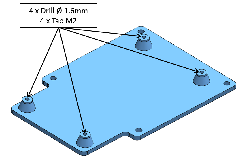


## View the Teststand Cad Model in your Web Browser

*Leg Test Stand v2 - Click on the picture to view the cad model in your browser*
* You can download the Solidworks CAD files [here](solidworks_files/leg_test_stand_v2.zip).
## More Information
[Open Dynamic Robot Initiative - Webpage](https://open-dynamic-robot-initiative.github.io)
[Open Dynamic Robot Initiative - YouTube Channel](https://www.youtube.com/channel/UCx32JW2oIrax47Gjq8zNI-w)
[Open Dynamic Robot Initiative - Forum](https://odri.discourse.group/categories)
[Open Dynamic Robot Initiative - Paper](https://arxiv.org/pdf/1910.00093.pdf)
[Hardware Overview](../../README.md#open-robot-actuator-hardware)
[Software Overview](https://github.com/open-dynamic-robot-initiative/open-dynamic-robot-initiative.github.io/wiki)
## Authors
Felix Grimminger
## License
BSD 3-Clause License
## Copyright
Copyright (c) 2019-2021, Max Planck Gesellschaft and New York University


