 v1.4
v1.4
For documentation on new version of emonTx (V2.0) see here
emonTx stands for Energy Monitoring Transmitter.
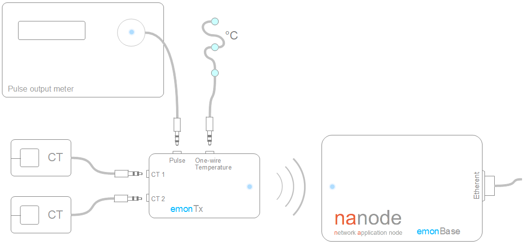
It's a small wireless energy monitoring node. It's designed to take inputs from multiple CT sensors, optically from a pulse-output utility meter and from multiple one-wire temperature sensors. It is designed to be powered by 2x AA batteries or 5V USB.
Interested in the emonTx? Please fill in the interest form
Buy an emonTx V1.4 kit
 |
 |
 |
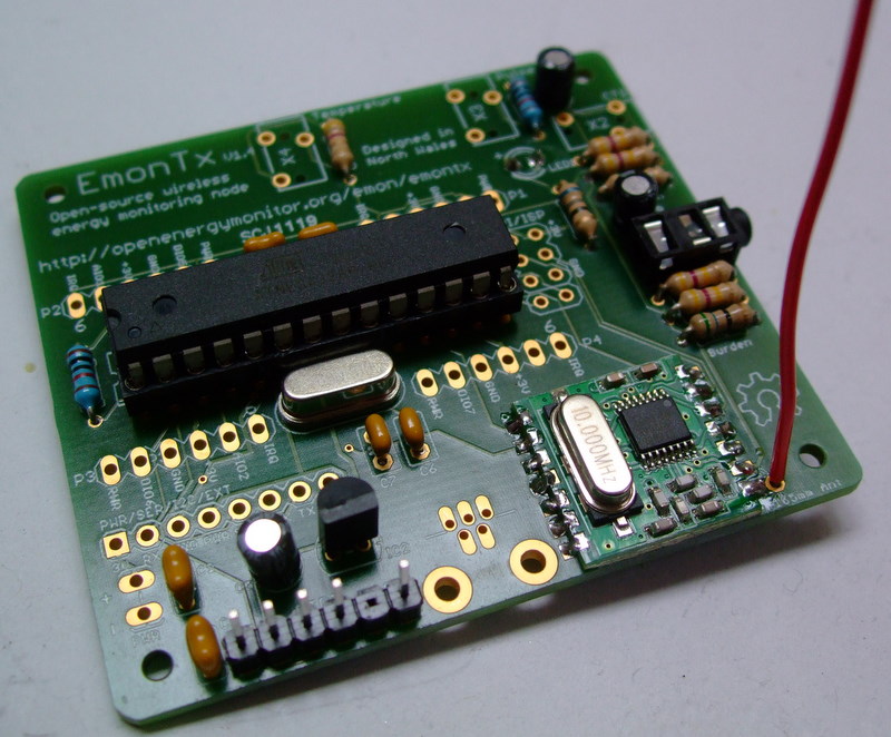
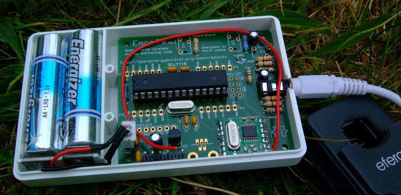
above: emonTx V1.4 with one CT channel soldered in
emonTx is based on the Atmega328 8-bit micro-controller and is fully compatible with Arduino IDE. An FTDI to USB cable is required for programming.
The design is based on the JeeNodeV5, is fully open-source and is designed for easy expandability and compatability with JeeLabs shields.
Applications
- Electricity consumption monitoring
- Renewable generation monitoring
- Heatpump monitoring
- Water and gas monitoring (from pulse output meter)
- Temperature monitoring
- Large scale monitoring - up to 29 emonTx's can potentially transmit to a single base station
Hardware
- Based on JeeNodeV5 design - many thanks to Jean-Claude Wippler for sharing his good work
- Compatible with most JeeNode shields (JeeNode ports P2 and P3 fully available)
- Designed to run on 3.3V and be powered by 2x AA batteries
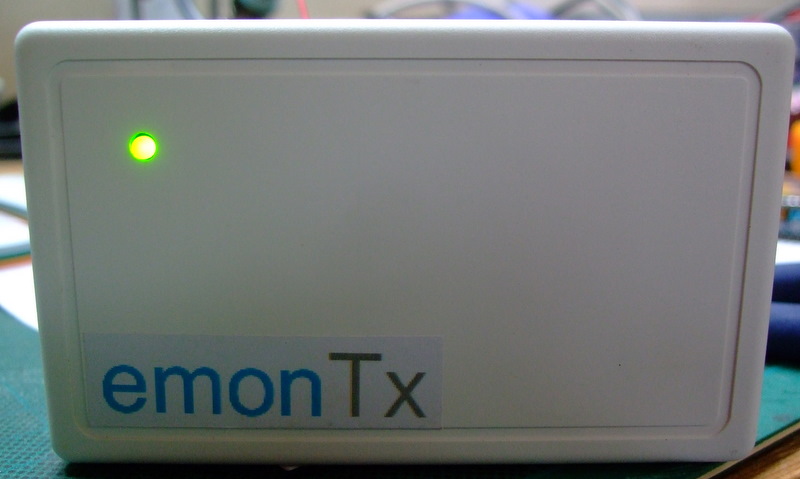
- Designed to fit in this case
- Uses 2.5mm jack plug connections
- Can be powered using 5V mini-USB
- Requires FTDI cable for programming
Energy Monitoring
- 2 x CT monitoring channels - based on OpenEnergyMonitor design using efergy CT sensors
- 1x pulse counting input for interfacing directly or optically (using TSL257 Light to Voltage sensor) with pulse output utility meters
Temperature
- Supports multiple DS18B20 digital temperature sensors on a one-wire bus. Potentially up to 16; limited by wireless data packet size.
Wireless
- Uses Hope Alpha RF / RFM12B Transceiver available on ISM band 433Mhz (All countries), 868Mhz (Europe only), or 915 MHz (US and Australia only). Country information taken from here. The OpenEnergyMonitor kit includes the 433Mhz module.
- Up to 30 emonTx's can potentially communicate with one emonBase station
- Up to 250 different network groups can potentially be setup in a single location
Power
The emonTx is designed to be powered by 2 x AA batteries or by 5v USB/FTDI. When powering the unit with 5V through the USB or FTDI header the on-board voltage regulator will reduce the voltage to 3.3V. The battery connection header is not regulated, therefore 3.3V max should be connected to the battery header. If higher voltage is connected the RFM12 is at risk of damage. The RFM12 can be run at 5V but it's outside it's recommended operating voltage
emonTx has been designed to be low power (see here for details of low power optimisation). Much power optimisation can be done in software like putting the Atmega and RF12 to sleep for periods of time. The following measurements were taken with two CT channel soldered in but the software was only reading from one channel:
0.1mA @ 3.13V = 0.31mW when Atmega and RF12 in sleep mode
6.7mA @ 3.13V = 21mW when RF12 in sleep mode
7.14mA @ 3.13V = 22.35mW when RF12 awake but not transmitting
14mA (approx) @ 3.13V = 43.8mW when RF12 is transmitting
This should give a battery life of almost 3 months if the Atmega is asleep for 4s and on for 332ms (the time taken to read from CT and calculate power over 1480 samples) assuming 2500mAh of AA battery capacity. Battery life calculation spreadsheet: download.
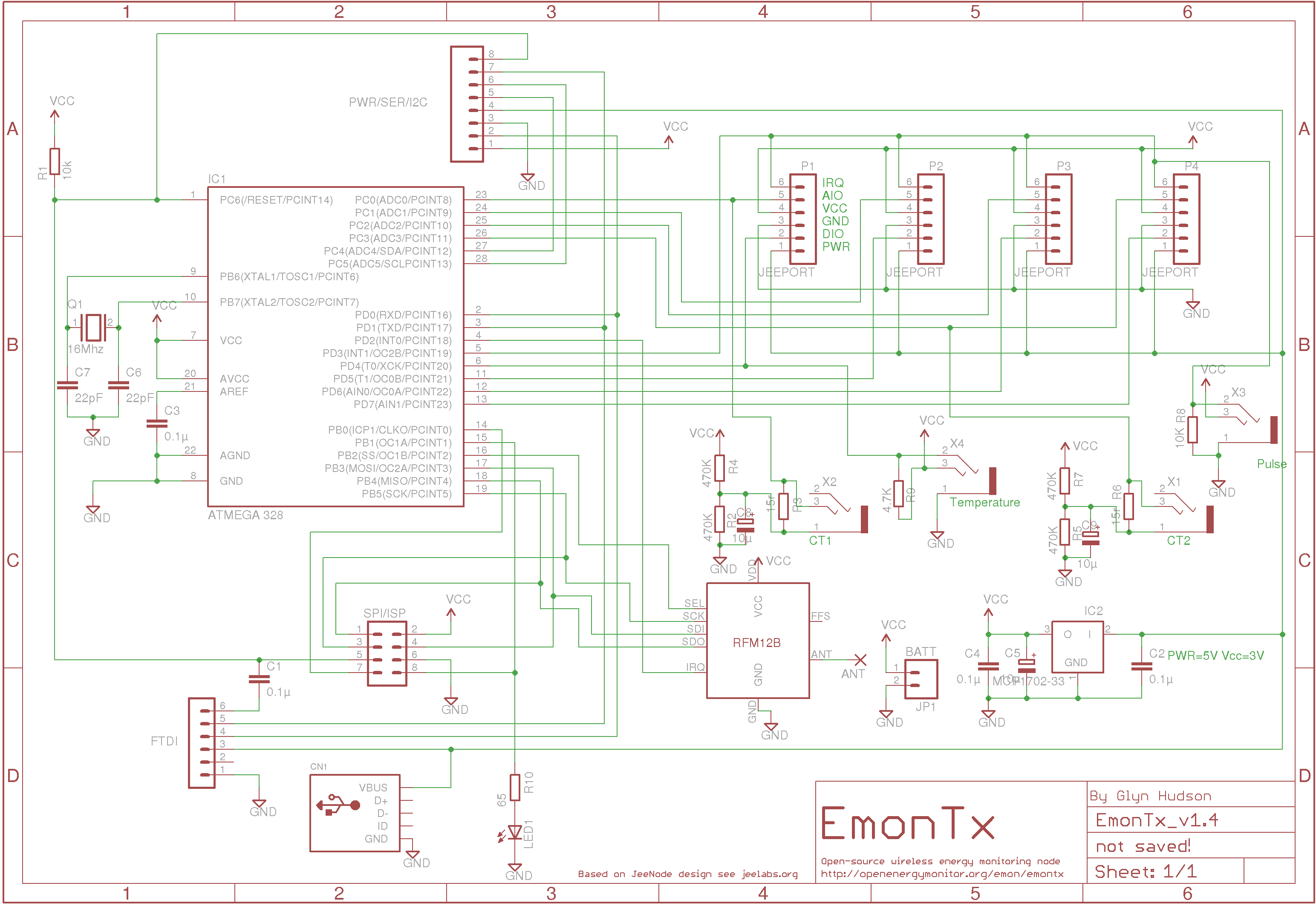
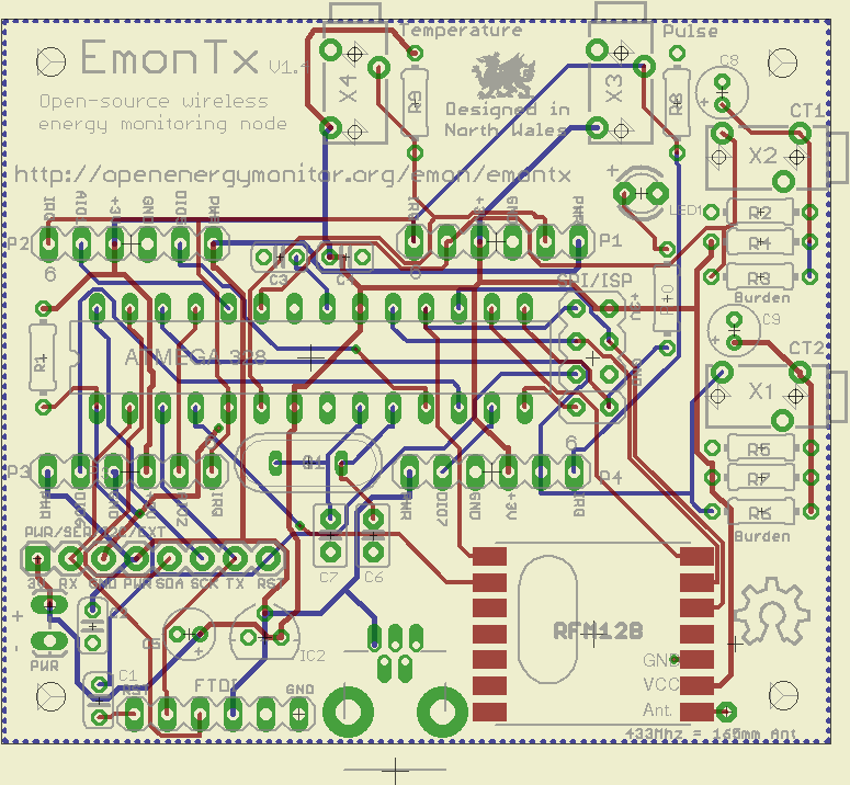
Schematic & PCB board layout:
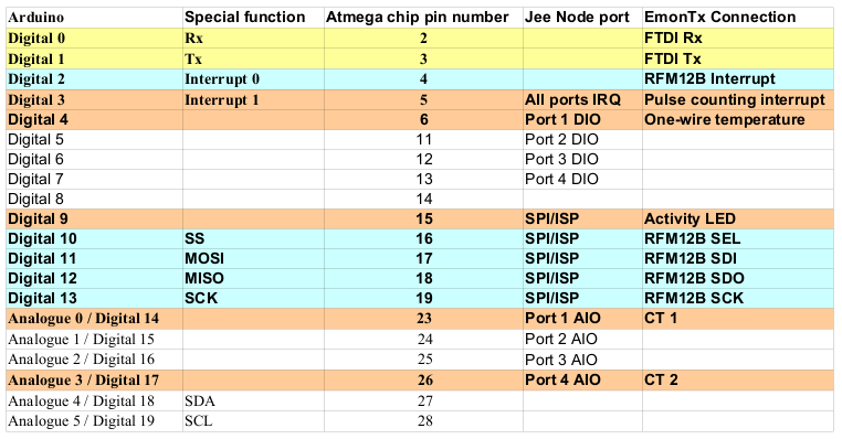
Port map:
Part List:
Change log
- V1.0 - first release
- V1.1 - corrected CT circuit error
- V1.2 - compleate re-route with GND plate added and singal wires increased to 10mill and power to 16mill. JeeNode offest header pins changed.
- V1.3 - compleate re-route with http://www.freerouting.net/. Reduced vias from 36 to 5!
- V1.4 fixed R9 (one-wire temp) to be pull-up not pull-down
- V1.5 Changed one-wire temperature connection 2.5mm jack-port to enable the use of standard mono 2.5mm jack-plug
- V.2.0 Added another channel to make 3 CT channels. Added option for voltage measurement for real power measuremements. Chaged to 3.5mm CT jacks for compatability with seedstudio CT's
emonBase / NanodeRF
The base station will receive the wireless signal from one or more emonTx's and post the data online either to Pachube or a server installation of emoncms
The base station development is a collaboration between OpenEnergyMonitor and Nanode (Ken Boak and London Hackspace) The emonBase comprises of a Nanode V.5 with the addition of the RFM12B wireless module. JeeLabs sell a breakout board for this. In the future we would developing a NanodeRF board to include the RFM12 module on a single PCB.
Older versions of the Nanode can be used with several modifications
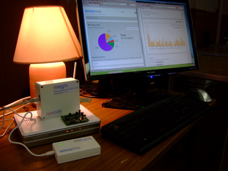
Nanode base and emonTx in action
Firmware
In development! Please contribute new examples and bug fixes
emonTx exmple code:
- Single CT wireless monitoring node example
- One-wire temperature + CT example
- Interrupt Pulse Counting (in development)
emonBase/Nanode RF example code:
Environmental & Life Cycle
Every effort has been made to reduce the environmental impact of the emonTx. The board has been designed on a laptop running off-grid powered by solar PV (see setup here).
The PCB board is manufactured in the UK using a lead free process.
All components are RoHS compliant
At the end of its useful life we will gladly accept the unit back. The Atmega 328 can easily be re-programmed for other purposes.
Licence

The emonTx hardware deisgnes (schematics and CAD files) are licensed under a Creative Commons Attribution-ShareAlike 3.0 Unported License.
The emonTx firmware is released under the GNU GPL V3 license
The documentation is subject to GNU Free Documentation License
The emonTx hardware designs follow the terms of the OSHW (Open-source hardware) Statement of Principles 1.0.

What this basicly means is that you are free to modify, re-distribute and use the design in a personal or commercial environment as long as you attribute OpenEnergyMonitor and make any resulting designs or derivatives available under the same open-source licenses. Read more about open-source...


Re: emonTx V1.4
That's the sort of comment I like, well done for finding it yourself! Let me know if you need other parts. Do you mind me asking what you are designing?
Glyn.
Re: emonTx V1.4
How is your DRC settings in Eagle ?
Re: emonTx V1.4
No problem. I do a wireless weather station. It's very similar to your project, I want to have a base with several sensors(SHT21, BMP85, analog wind sensor oraz simple LDR) and two receivers. One with LED display, second connected so router or computer via USB port. Router with OpenWrt frmware receive data and plot graphs.
Another project is energy monitor shield to arduino, but here i use RF modules form seedstudio.
Re: emonTx V1.4
Sounds interesting. Let us know when you have something to show and we will post a link to it in 'Builds and Case Studies' section. Suneil Tagore recently documented a wind speed and wind turbine energy datalogger for the site. If it helps you at all, here is the link: http://openenergymonitor.org/emon/node/135
Good luck with your project.
Glyn.
Re: emonTx V1.4
Nice design...
Just a note. If you only use 2 AA batteries the available voltage will not be able to drive the LDO so as to give you the 3.3V for the Vcc..
Harry
Re: emonTx V1.4
Hi Harry,