
DELULUBOTS
Delulu Today, Limitless Tomorrow.
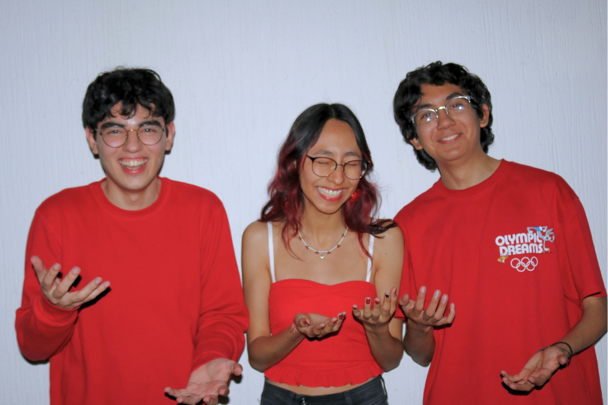
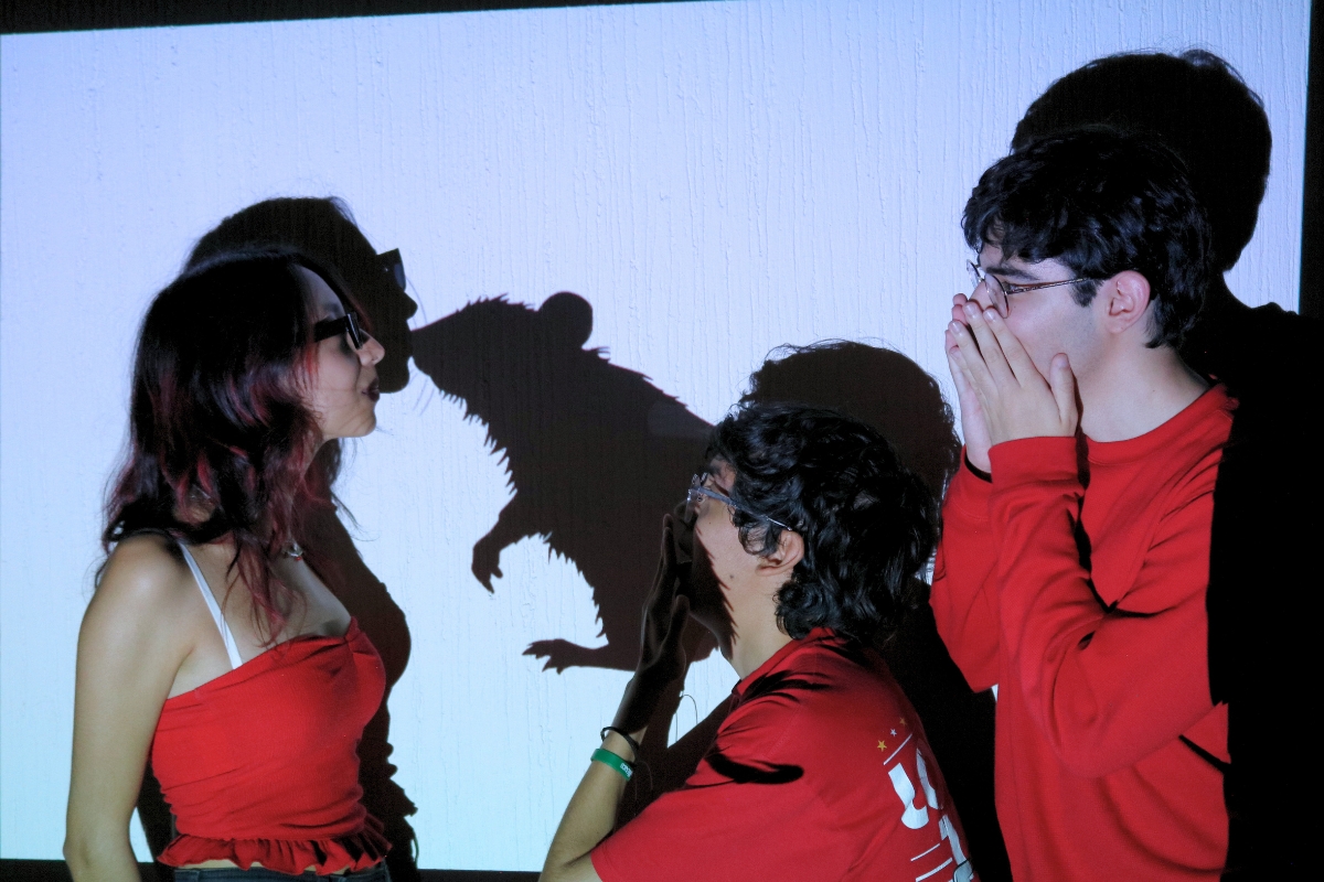

| ## **Saori Jasso** **Electronics · PCB Designer · Software Developer** **Age:** 19 I am an **Information Technology Engineering student** and was responsible for the robot’s electrical system, from **selecting components and designing the PCB** to developing the systems that allow it to power on with just two buttons. I also contributed to the **software development** and was responsible for **designing and building our DIY Game Field** for testing and practice. WRO gave me the opportunity to design my **first PCB** and challenge myself with technologies I had never worked with before. Since middle school, robotics has been one of my greatest passions, and I hope to **inspire more girls to explore STEM, pursue engineering, and discover the same passion for robotics.** |

|
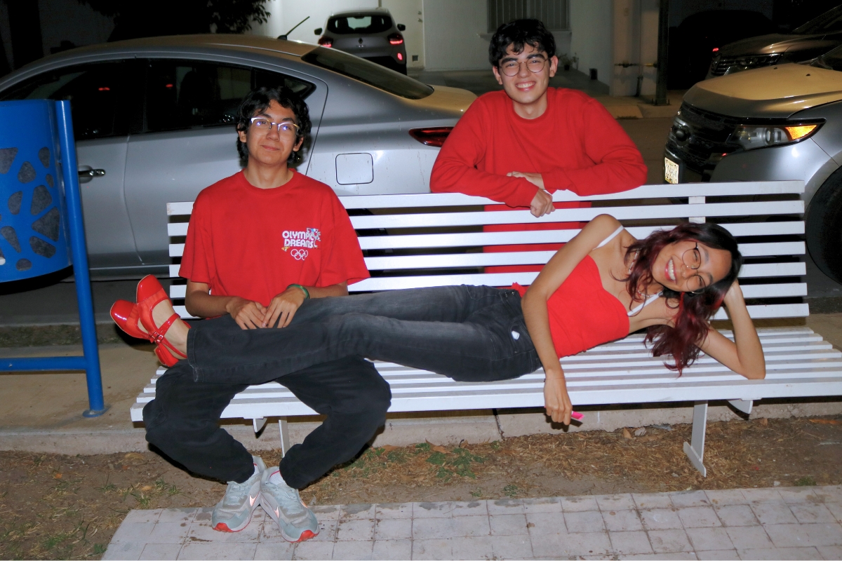
| ## **Jesús Morales** **Mechanical & CAD Designer · Software Developer** **Age:** 19 I am an **Information Technology Engineering student** and served as the Mechanical & CAD Designer and Software Developer for our robot. This project marked my first time fully designing an **entire mechanical system from scratch in CAD**—a challenge that required balancing spatial constraints, weight distribution, and structural integrity. My passion for technology started at a young age, but growing up in my hometown, hands-on STEM opportunities were limited. Moving to Mexico gave me the chance to explore robotics throughout my school years, shaping my path into engineering. WRO has been an incredible opportunity to **push my technical limits**, and I hope to inspire others to pursue STEM regardless of their background. |

|
| ## **Kevin Rucoba** **Coach** **Age:** 21 I am a **Software Development Engineering student** and have supported and advised the team throughout all areas of the project. From helping with **technical challenges and brainstorming ideas** to guiding decisions and overcoming unexpected problems, I've always been there to provide a different perspective when needed. My goal is to **support their ideas, share my experience, and help them turn their ideas into reality** while encouraging them to learn, experiment, and grow as a team. I also helped the team stay focused on our goals, encouraged us to keep improving after setbacks, and shared the experience needed to approach challenges with **confidence, creativity, and perseverance**. |
|
Open Challenge
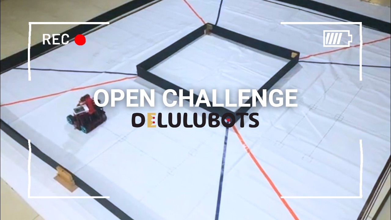
Watch the Open Challenge Video |
Obstacle Challenge
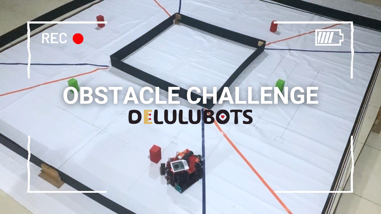
Watch the Obstacle Challenge Video |
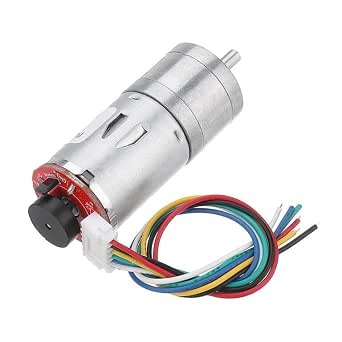
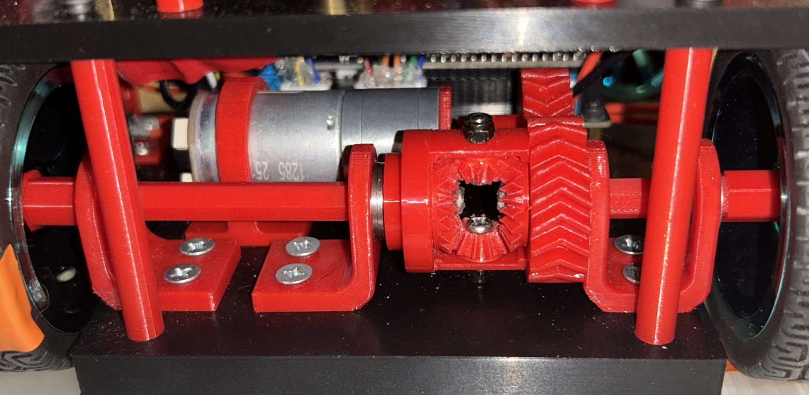 **Motor: GM25-370, 12V, 330 RPM**
The datasheet gives a continuous rated torque of 0.57 N·m (at 1.7 A) and a stall torque of 1.18 N·m (at 5.6 A). Since the robot is constantly driving and the wheels are never locked, we only use the continuous rating to size the system.
Our model requires 0.087 N·m, which is only about 15% of this motor's continuous capacity. We deliberately took the weight penalty of an oversized motor for a few practical reasons:
1. **Thermal Headroom:** Operating a motor near its limit generates a ton of heat. Staying at ~15% load keeps the motor completely cool, meaning we don't experience any RPM sag or battery voltage drops toward the end of a run.
2. **Friction Buffer:** If the official competition mat turns out to be much stickier than our tarp, this torque buffer gives us enough margin to avoid stalling in normal operation.
3. **Overcoming Mechanics:** The extra torque easily powers through the friction of our PETG differential, keeping our PID speed control crisp and responsive.
**Driver: Transitioning to the BTS7960**
We originally prototyped with a TB6612FNG driver, but realized it was a major single point of failure. It's only rated for 1.2 A continuous per channel, and our motor can spike up to 5.6 A if it stalls (like bumping a wall or getting stuck).
Instead of risking a blown driver on the track, we swapped to a **BTS7960**. It’s rated for 43 A. It takes up more space on the chassis, but it greatly reduces the chance of the driver overheating. We chose reliability over spatial economy.
---
#### 3D Printing & Structural Optimization
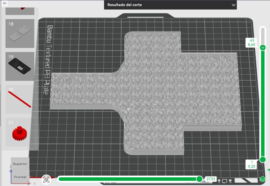 To iterate quickly, we 3D printed all our custom mechanical parts using **PETG**, which gives us much better impact resistance and layer adhesion than standard PLA.
**Prototyping phase:**
We printed early test fits using an **8% Gyroid infill**. It allowed us to print super fast and save filament during the trial-and-error phase. The Gyroid pattern distributes stress equally across the X, Y, and Z axes, so the pieces held their shape well. However, when we actively applied manual stress tests to find their limits, they eventually snapped. This proved they were strictly prototypes and nowhere near strong enough to survive the mechanical stress of a real competition.
**Final Production Parts:**
For the final parts, we prioritized reliability so we optimized the slicer settings to get as much strength as possible without adding too much weight:
* **Wall Loops:** Increased from 2 to 3.
* **Top/Bottom Shells:** Increased from 2 to 3.
* **Gyroid Infill:** Bumped slightly to 15%.
**The result:** With these settings, we were able to add strength mainly where it matters without adding too much material. This kept our parts structurally rigid without unnecessarily increasing our total mass or messing up our calculated acceleration dynamics.
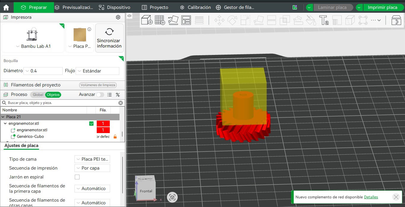 **Targeted Reinforcement: Motor Gear Hub**
During testing, we discovered a localized failure mode in our differential. The primary drive gear mounts directly to the motor's D-shaft. Due to the continuous torque and friction from sudden acceleration, the D-shaped hole inside the PETG gear was deforming and wearing out into a circle, causing the motor shaft to spin freely without turning the transmission.
Instead of printing the entire gear with 100% infill (which would add unnecessary mass and print time), we added a cylindrical modifier in Bambu Studio specifically around the mounting hub. We assigned 6 wall loops exclusively to this modifier. This generated a highly dense, rigid core to grip the D-shaft perfectly, while leaving the outer gear teeth at the standard 15% infill, solving the stripping issue completely.
#### Steering and Traction Mechanism
We selected an **Ackermann steering system** based on the turning requirements of our robot and the characteristics of the competition field. We considered conventional steering, Ackermann steering, and anti-Ackermann steering as possible solutions.
| Steering System | Turning Geometry | Tire Slip | Low-Speed Maneuverability | Mechanical Complexity | Alignment Requirements | Suitability for Our Robot |
| :--- | :--- | :--- | :--- | :--- | :--- | :--- |
| **Conventional Steering** | Both front wheels use approximately the same steering angle | Higher during tight turns because the wheels follow different turning radii | Moderate | Low | Low | Limited |
| **Ackermann Steering** | Inner wheel turns more than the outer wheel, allowing both wheels to follow their respective turning radii | Low | High | Medium | Medium–High | **Excellent** |
| **Anti-Ackermann Steering** | Inner wheel turns less than the outer wheel | Can be advantageous in specific high-speed conditions, but may increase slip at low speeds | Low–Moderate for our application | Medium | Medium–High | Limited |
We selected Ackermann because it allows the inner and outer front wheels to follow different turning radii, reducing unnecessary tire slip during turns and providing more predictable steering behavior.
This decision was also connected to our drivetrain architecture. Since the robot uses mechanically driven wheels rather than independently controlled drive wheels, we needed a steering solution that could provide precise directional control without using differential wheel speeds as the steering mechanism. Ackermann steering allowed us to separate the steering function from the traction system while maintaining a compact mechanical architecture.
#### Steering Geometry
The steering geometry was designed in CAD using the Ackermann principle. Instead of assigning the same steering angle to both front wheels, we constructed the geometry so that the steering axes of the front wheels converge toward a common **instantaneous center of rotation**.
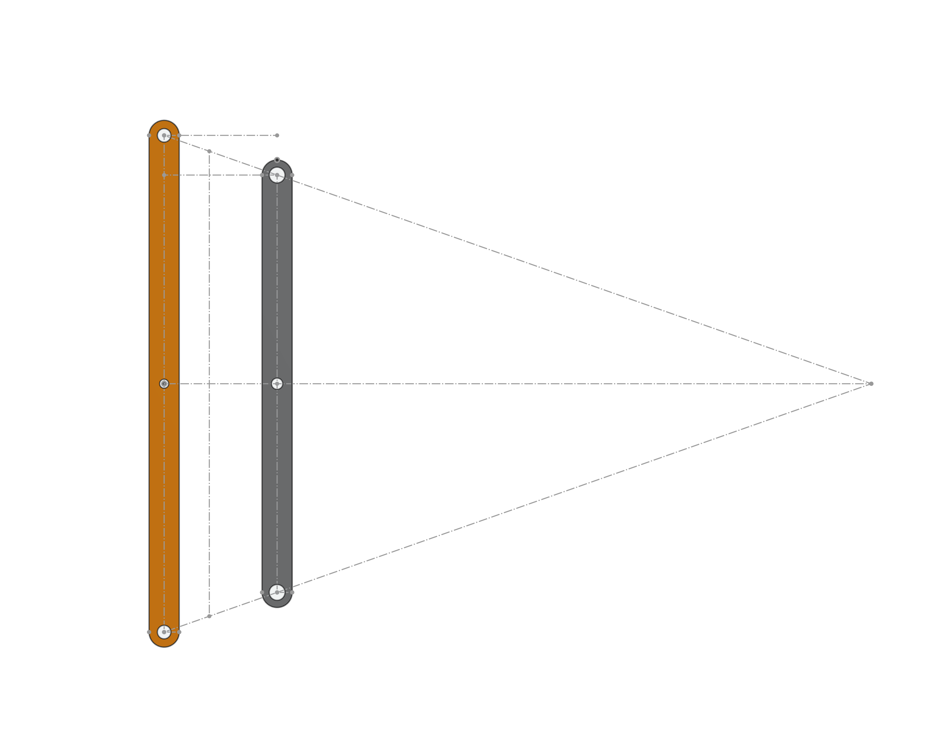
*CAD construction used to define the Ackermann steering geometry.*
This geometry determines the relative steering angles of the front wheels: the **inner wheel turns through a greater angle than the outer wheel** because it follows a smaller turning radius. This reduces unnecessary tire slip and allows the robot to maintain a more predictable trajectory during turns.
The CAD sketch was used to determine the position of the steering pivots and linkage attachment points before manufacturing the mechanism. This allowed us to translate the theoretical Ackermann geometry into a physical linkage while accounting for the available space, wheel position, and required steering range.
The steering mechanism consists of the **steering servo, servo arm, fixed steering support, linkage rods, steering arms, and front wheel assemblies**. The servo provides the input rotation, which is transferred through the linkage to both steering arms. The geometry of the steering arms produces the different steering angles required by the Ackermann configuration.
#### Space Optimization
The front section of the robot had limited space because the **front wheels, steering mechanism, and servo** had to fit within the same area. Rather than adding a separate structure to support the steering linkage, we integrated the **servo mount with the fixed steering support**.
The servo mount therefore serves two functions: it securely holds the servo and acts as the stationary reference point for the steering linkage. Small arms extending from this support provide the attachment points for the linkage rods, while the rest of the steering mechanism moves around this fixed structure.
This integration reduced the number of separate components and allowed us to make better use of the available space. It also reduced material usage while maintaining the rigidity required by the steering mechanism.
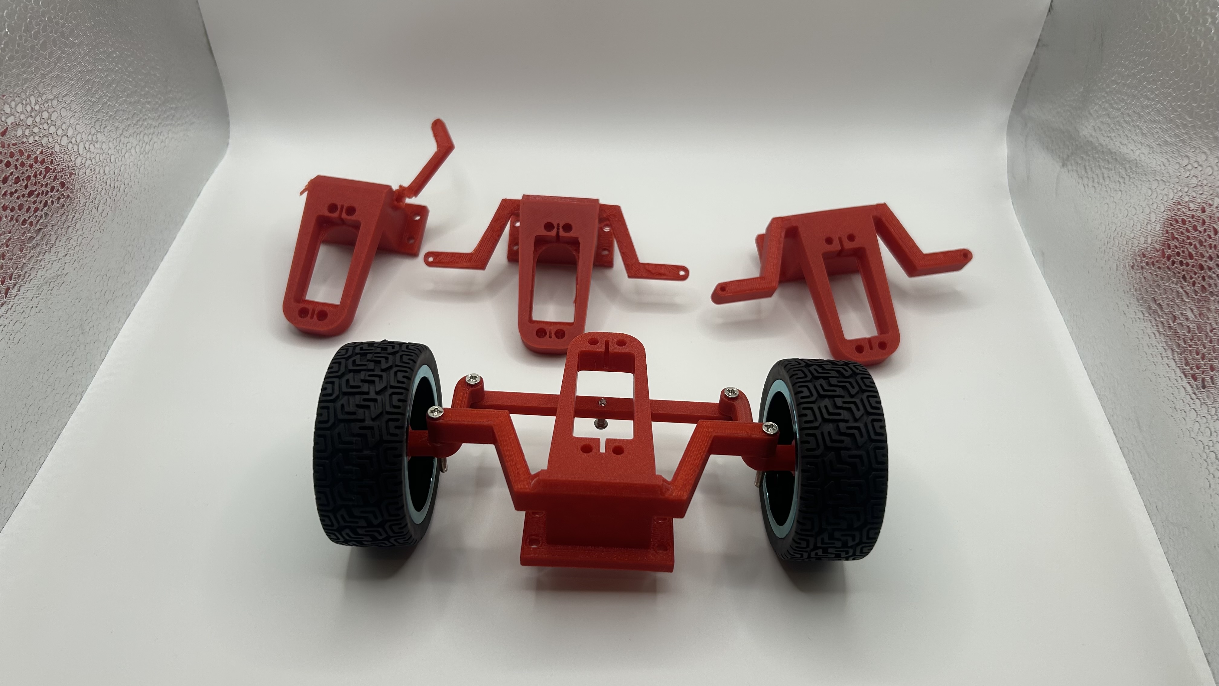
*Evolution of the servo support through different design iterations, showing the modifications made to improve its integration, stability, and fit within the steering mechanism.*
This was an example of adapting the theoretical steering geometry to the physical constraints of the robot rather than treating the steering system independently from the rest of the chassis.
#### Mechanical Differential
The Ackermann steering geometry also created a requirement for the traction system: the driven wheels need to be able to rotate at **different speeds during a turn**.
During a turn, the inner wheel follows a smaller radius than the outer wheel and therefore travels a shorter distance. If both driven wheels were rigidly connected to the same axle, they would be forced to rotate at the same speed. This would cause tire slip and introduce additional mechanical stress.
To solve this, we implemented a **mechanical open differential**. This allows both driven wheels to receive power from the same drivetrain while permitting them to rotate at different speeds when cornering.
We selected a mechanical differential because it provides this speed difference mechanically, without requiring independent control of the driven wheels. This complements the Ackermann steering geometry while keeping the drivetrain compact.
The differential uses **20-tooth side gears and 12-tooth spider gears**. The side gears are connected to the driven axles, while the spider gears transfer torque between them and allow relative rotation between the two sides.
The main drive gear maintains a **1:1 relationship with the motor output**, preserving the available motor speed without introducing an additional reduction stage at the differential.
#### Differential Iterations
Our drivetrain went through several iterations before reaching the final configuration. The first prototype used **spur gears** both in the motor-to-differential transmission and within the differential.
| Initial Prototype | Final Design |
| :---: | :---: |
| 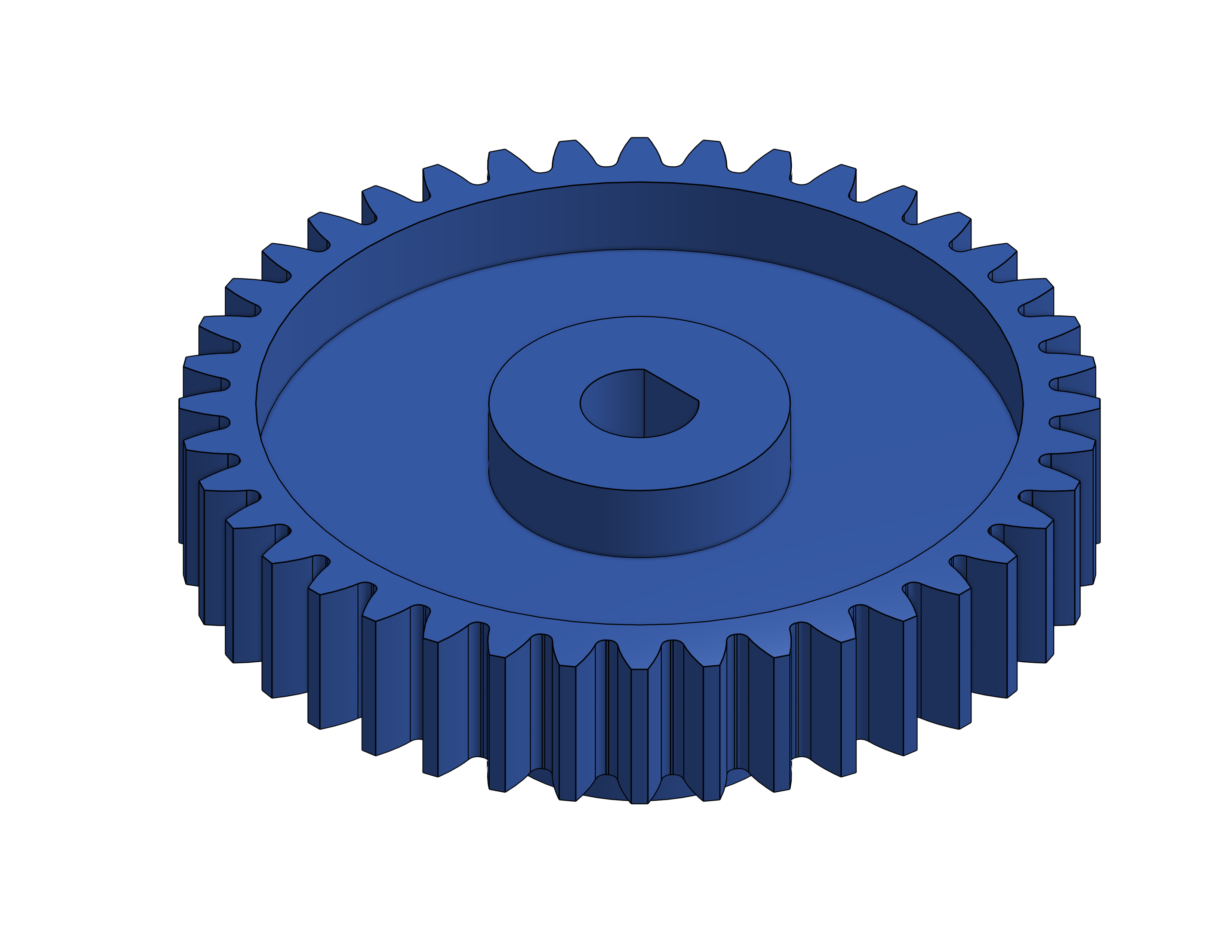 | 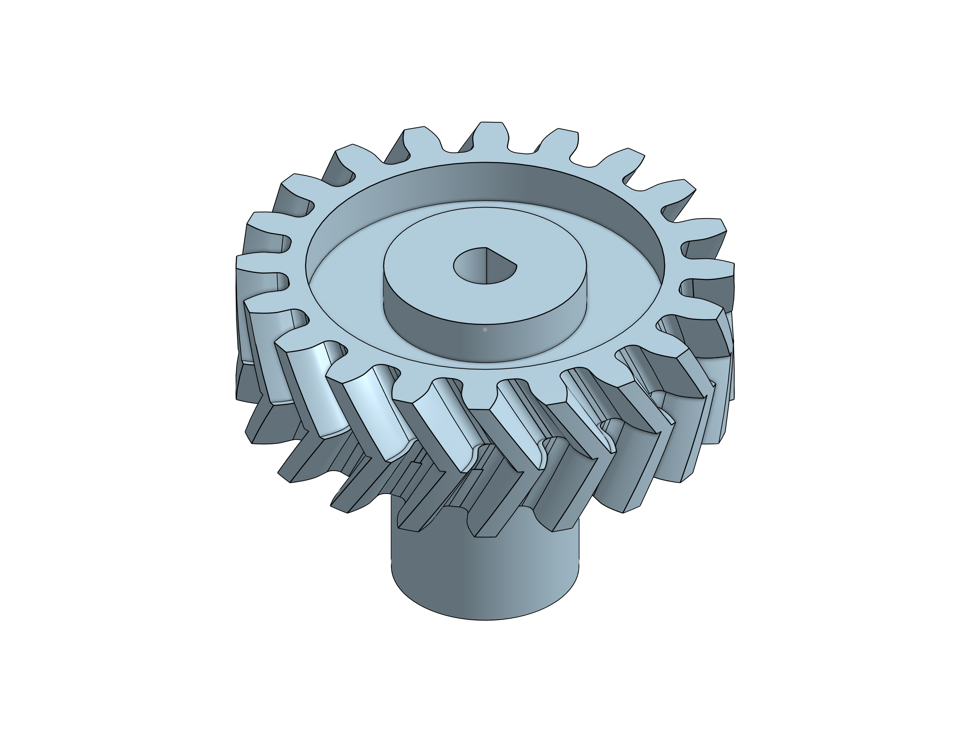 |
| *Spur gear* | *Final reinforced gear* |
| 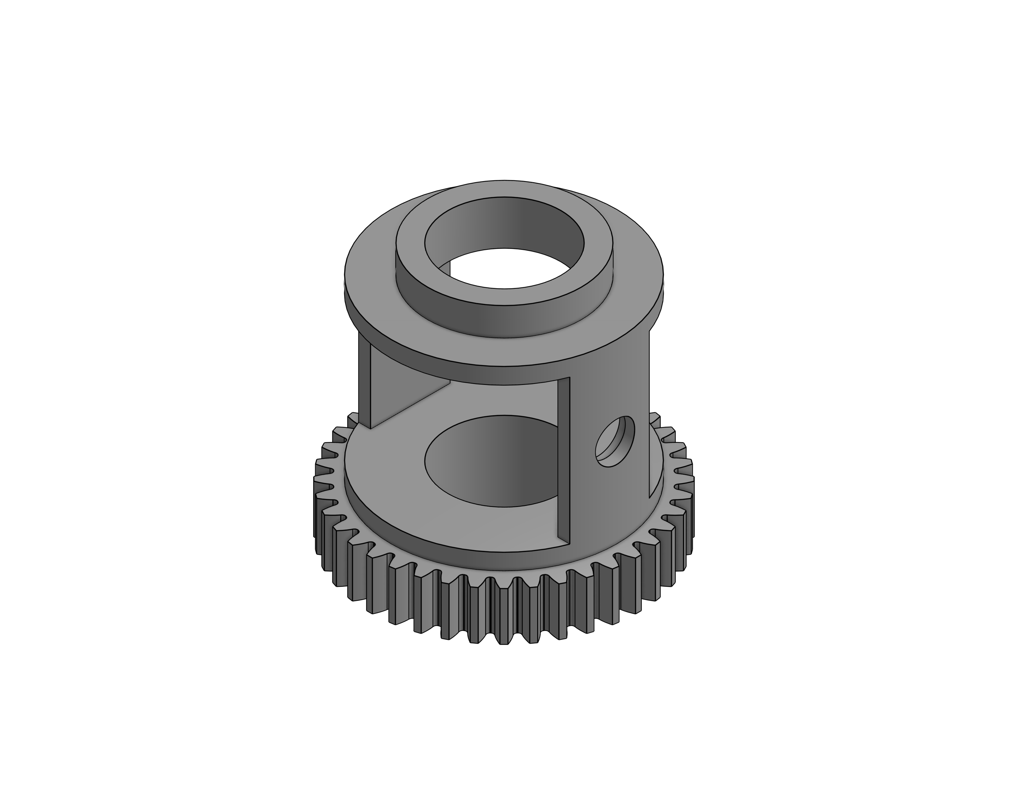 | 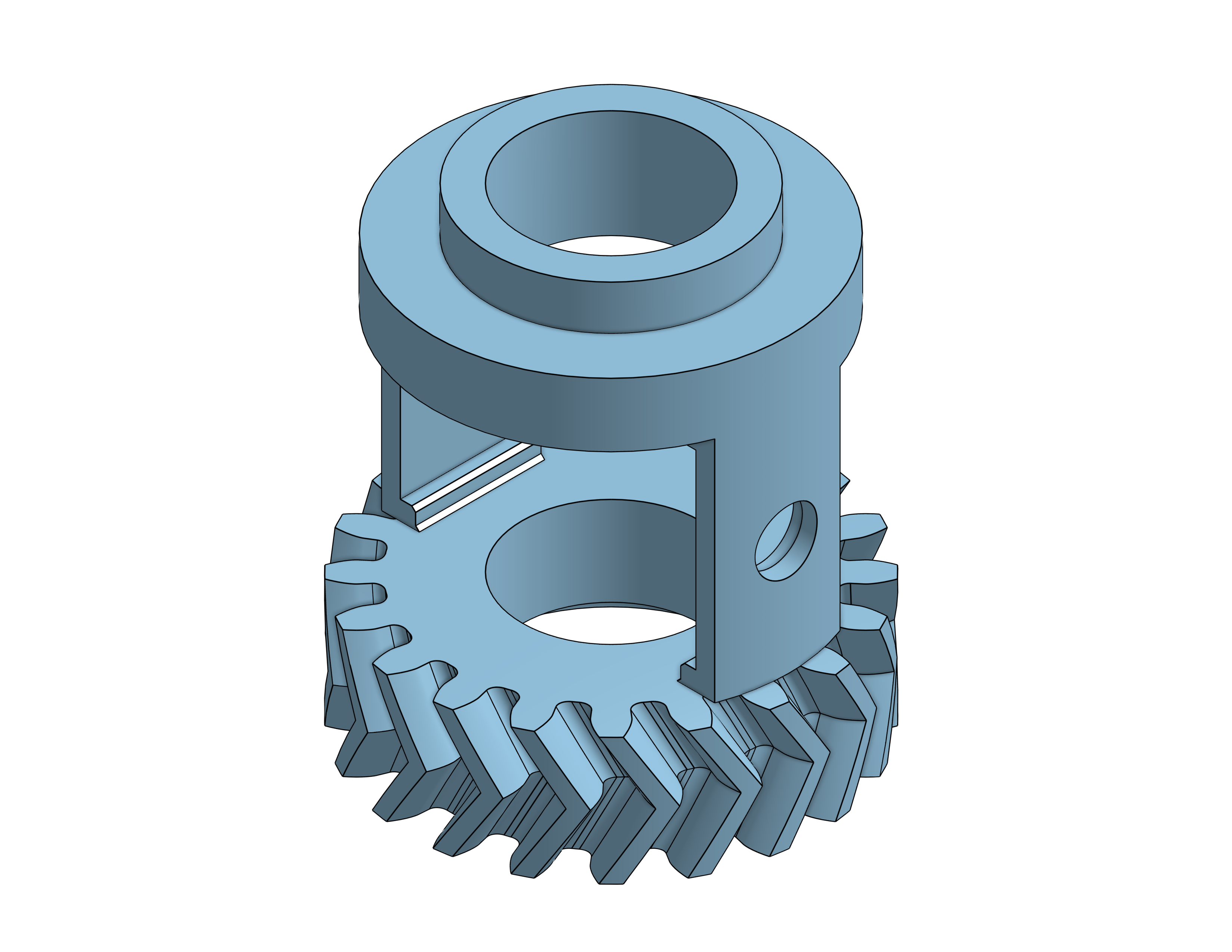 |
| *Initial differential* | *Final differential* |
*Evolution of the drivetrain from the initial spur-gear prototype to the final design.*
The initial version allowed us to validate the basic drivetrain concept and confirm the interaction between the motor and differential. However, testing revealed several mechanical weaknesses that led to subsequent iterations.
The main gears were initially designed as **spur gears**. We later changed them to **herringbone gears** to improve resistance to lateral movement and maintain better alignment during operation.
#### Axle Support Iteration
During testing of the initial differential housing, we observed that the driven axles were supported at only two points. This allowed the shafts to deflect under their own load and during operation, causing them to become slightly misaligned with the differential gears.
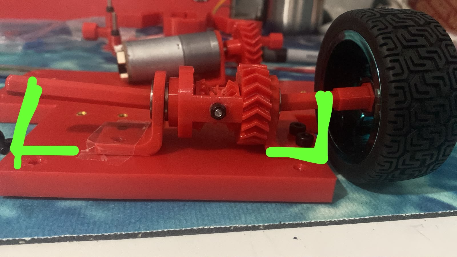
*Initial axle configuration showing shaft deflection caused by insufficient support.*
To address this issue, we redesigned the rear support structure to provide an additional support point for the driven axles.
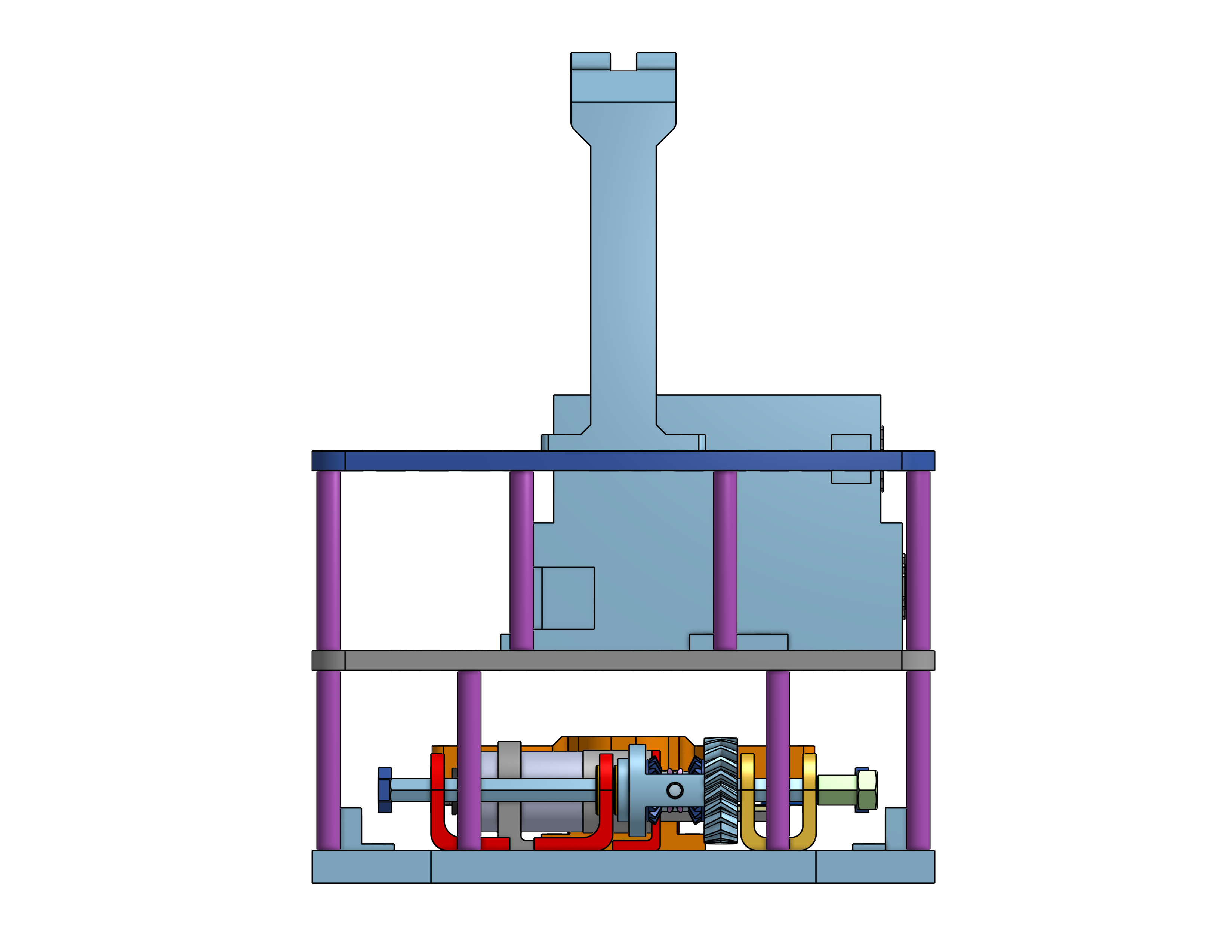
*Axle support redesign adding an additional constraint point to reduce shaft deflection.*
The additional support constrains the shafts along a greater portion of their length, reducing unwanted movement and helping maintain consistent alignment between the axles and the differential gears.
This modification was made specifically in response to the deformation observed during testing. Rather than increasing the overall size of the differential housing, we added support only where the deformation occurred. This improved structural stability while keeping the mechanism compact.
Additionally, the supports holding the spider gears were initially too thin and fragile. We increased their thickness and added reinforcing tabs connecting them to the main differential body. Because changing the spacing between these supports would affect the existing gear geometry, the reinforcement was added without changing their position.
Finally, during testing of the first herringbone version, the main gears could still separate slightly under load, causing the teeth to skip. We modified the differential housing to keep the gears closer together and maintain consistent tooth engagement.
These iterations allowed us to improve the drivetrain based on problems observed during physical testing, resulting in a final differential with improved **gear alignment, shaft support, structural rigidity, and power transmission reliability**.
#### Motor Support
The motor support was developed to securely hold the drive motor while maintaining its position relative to the drivetrain. In the initial version, the motor was not fully enclosed by the support structure.
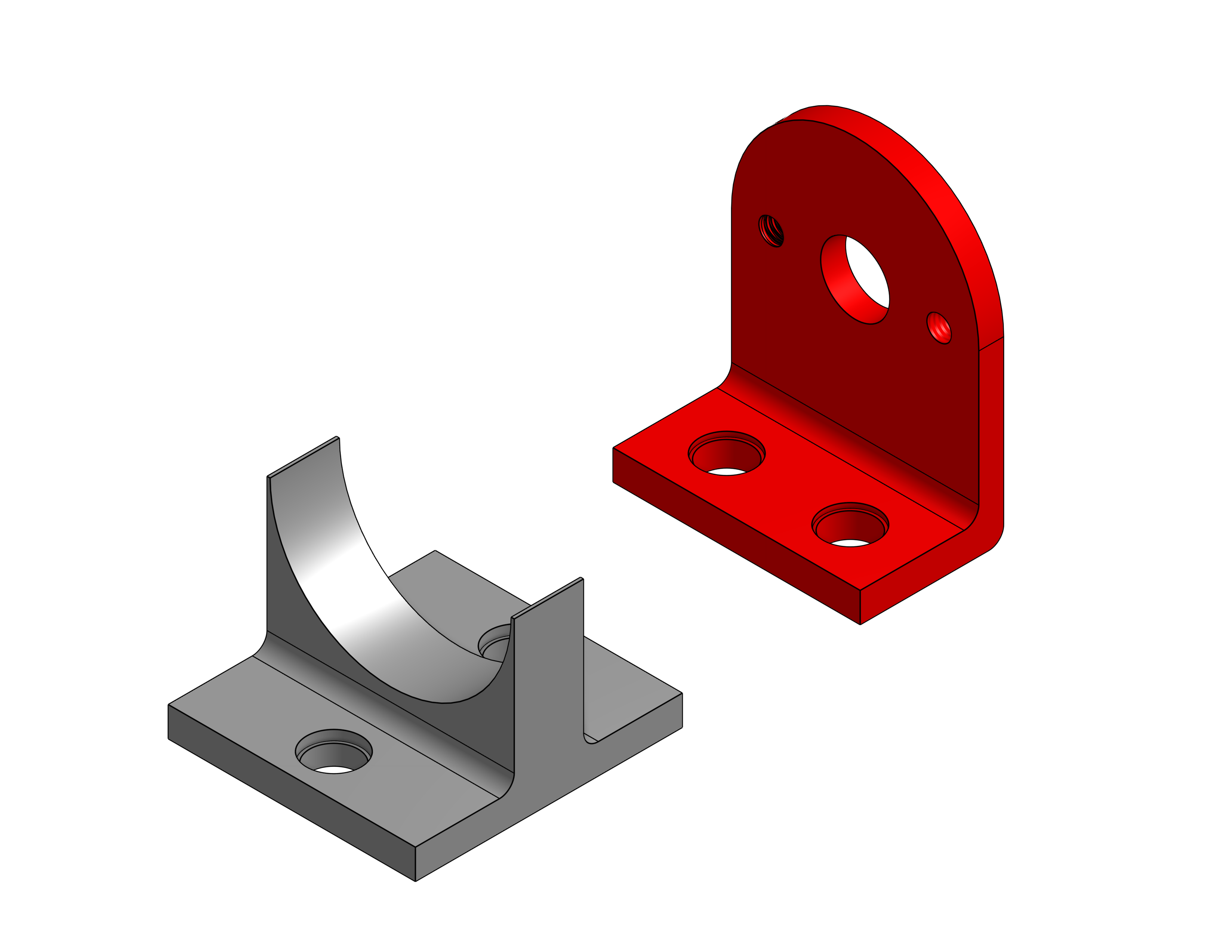
*Initial motor support design with limited constraint around the motor.*
During testing, we observed that the torque generated by the motor caused the support to tend to move upward. This movement could affect the position of the motor and consequently the alignment between the motor output gear and the drivetrain.
To address this issue, we redesigned the support to provide greater constraint around the motor body.
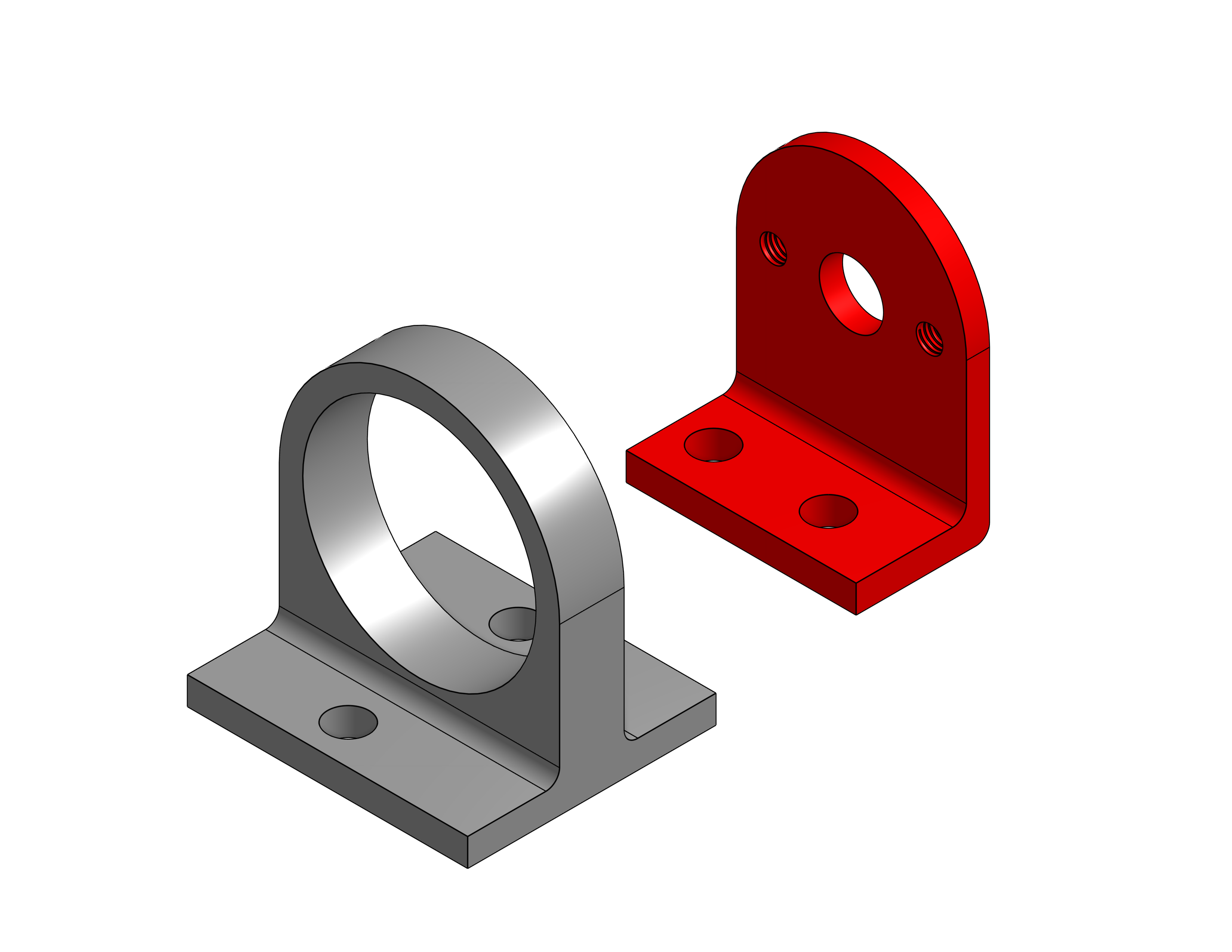
*Final motor support design providing greater constraint around the motor.*
The modification increased the stability of the motor mounting structure and helped maintain consistent alignment with the drivetrain during operation. Rather than increasing the size of the surrounding chassis, the support was reinforced specifically in the areas where movement was observed.
### 3.2. Power and Sense Management
This section details the hardware architecture of our vehicle, covering **component selection and strategic placement**, **power distribution**, **wiring schematics (including custom PCB design)**, **sensor calibration protocols**, and **systematic power testing strategies**.
Our design methodology goes beyond connecting components to achieve basic functionality. We engineered an electrical ecosystem focused on **reproducibility**, **safety**, **noise isolation**, and **rapid pre-competition validation**—ensuring every hardware decision directly supports our vehicle’s autonomous performance goals.
> [!NOTE]
> **Key Engineering Focus:** Prioritizing power stability through dual-battery domain isolation, noise decoupling, and custom PCB power distribution to withstand dynamic competition conditions.
### Section Overview
This module is organized into six core architecture deliverables:
| Module | Key Deliverables & Specifications |
|---|---|
| 01. Control Architecture | Dual-controller processing hierarchy (Raspberry Pi 5 + ESP32) and UART communication flow. |
| 02. Power System Architecture | Dual-domain battery isolation (2500 mAh logic & 2300 mAh actuators), voltage regulation rails, and safety protocols. |
| 03. Power Budget & Runtime | Worst-case current consumption matrix, mathematical power models, and battery life estimations. |
| 04. Component Specifications | Comprehensive procurement matrix, hardware parameters, engineering rationale, and placement strategy. |
| 05. Iterative Hardware Prototyping | Pre-PCB circuit mapping, hand-drawn schematics, and preliminary electrical testing. |
| 06. Custom PCB Integration | Carrier board design, dual-switch power activation, decoupling strategies, and trace routing. |
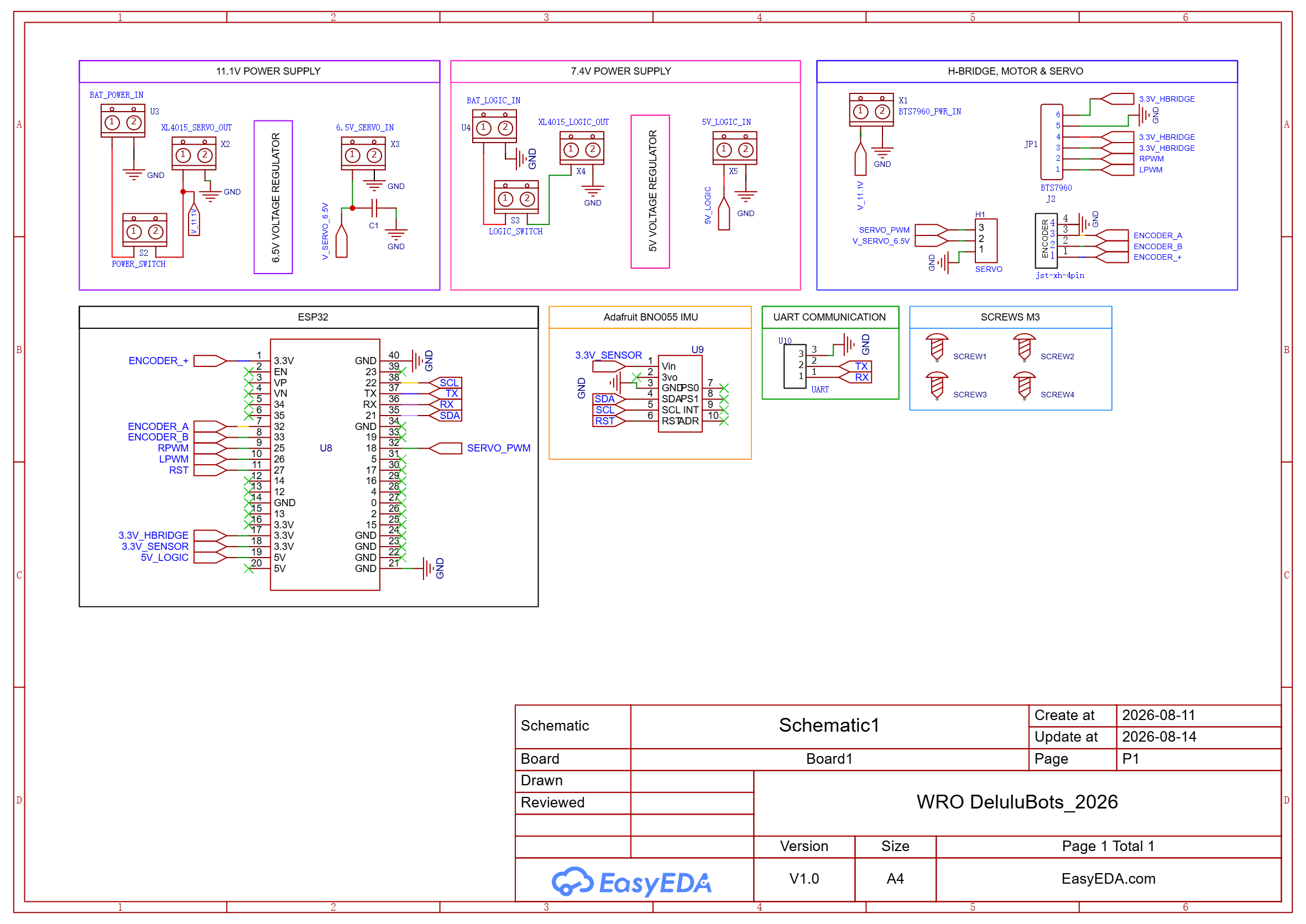
Official electrical schematic detailing power distribution and signal routing.
 |
 |
---
### Reliability and Safety Considerations
#### Reverse Polarity Prevention
One of the most critical foreseeable assembly failures during rapid pit-stop battery swaps is reverse polarity connection. To eliminate this risk, the power distribution system does not rely solely on color-coded wire conventions (red/black):
* **Actuator Domain (11.1 V LiPo):** Terminates in a high-current **keyed XT60 connector**.
* **Logic Domain (7.4 V LiPo):** Terminates in a dedicated **keyed JST-RC connector**.
Because both connector families are mechanically polarized and asymmetrical, they physically prevent inverted insertion. This implements a reliable mistake-proofing (poka-yoke) physical safeguard, eliminating human error during high-stress competition maintenance.
---
### Current Requirements & Power Budget
#### Component Current Demand Matrix
| **Component** | **Operating Voltage** | **Current Demand / Profile** | **Supply Source** |
| --- | --- | --- | --- |
| **GM25-370 Motor** | 11.1 V | ≤ 1.7 A (Nominal) \| ≤ 5.6 A (Stall) | Direct 11.1V LiPo (3S, 2300 mAh) |
| **BTS7960 Driver** | 11.1 V | Rated up to 43 A max peak | Direct 11.1V LiPo (3S, 2300 mAh) |
| **Hiwonder Servo** | 6.5 V | Variable dynamic load (≈ 0.8 A – 2.0 A) | 11.1V LiPo → XL4015 Buck (#2) |
| **Raspberry Pi 5** | 5.0 V | High-performance digital load (≈ 1.5 A – 3.0 A) | 7.4V LiPo → XL4015 Buck (#1) |
| **ESP32 MCU** | 5.0 V | Nominal logic load (≈ 160 mA – 240 mA) | 7.4V LiPo → XL4015 Buck (#1) |
| **BNO055 IMU** | 3.3 V Logic | Low power sensor load (< 15 mA) | ESP32 Onboard 3.3V Regulator |
| **Logitech Brio 100** | 5.0 V (USB) | Powered directly via USB bus | Raspberry Pi 5 USB Port |
#### Mathematical Power Calculations
Electrical power consumption is defined by:
**P = V × I**
**1. Nominal Motor Power Consumption:**
P(motor_nom) = 11.1 V × 1.7 A = 18.87 W
**2. Worst-Case Stall Electrical Condition:**
P(motor_stall) = 11.1 V × 5.6 A = 62.16 W
*The stall power (62.16 W) represents an instantaneous transient condition used to dimension PCB trace widths and thermal clearance margins.*
#### Battery Runtime Estimation
Theoretical operational runtime (t) is estimated using nominal battery capacities:
**t ≈ Capacity (Ah) / Average Current (A)**
* **Actuator Rail (11.1V LiPo, 2300 mAh):**
Actuator Runtime ≈ 2.3 Ah / 1.7 A ≈ 1.35 hours (≈ 81 minutes)
* **Logic Rail (7.4V LiPo, 2500 mAh):**
Logic Runtime ≈ 2.5 Ah / 2.0 A ≈ 1.25 hours (≈ 75 minutes)
> **Real-World Operating Margin:** Accounting for ≈ 90% DC-DC buck efficiency, CPU vision spikes, and keeping battery discharge above 20% capacity (3.3V/cell cutoff), total continuous competition runtime is estimated at **45–55 minutes**, far exceeding the required competition run length.
---
### Component Selection & Specifications
The following table details the key electronic and electromechanical components selected for our vehicle, including their core technical parameters, functional role, power/interface requirements, and engineering rationale.
| Component | Image | Key Specifications | Function | Power / Interface | Selection Rationale |
|---|---|---|---|---|---|
| GM25-370 Geared Motor (with encoder) |
 |
• 12V Nominal • 330 RPM • Metal Gearbox • Integrated Encoder |
Drive Propulsion | 11.1V Battery via BTS7960 Driver | Provides high torque and high encoder resolution for precise closed-loop speed control. |
| BTS7960 Motor Driver | 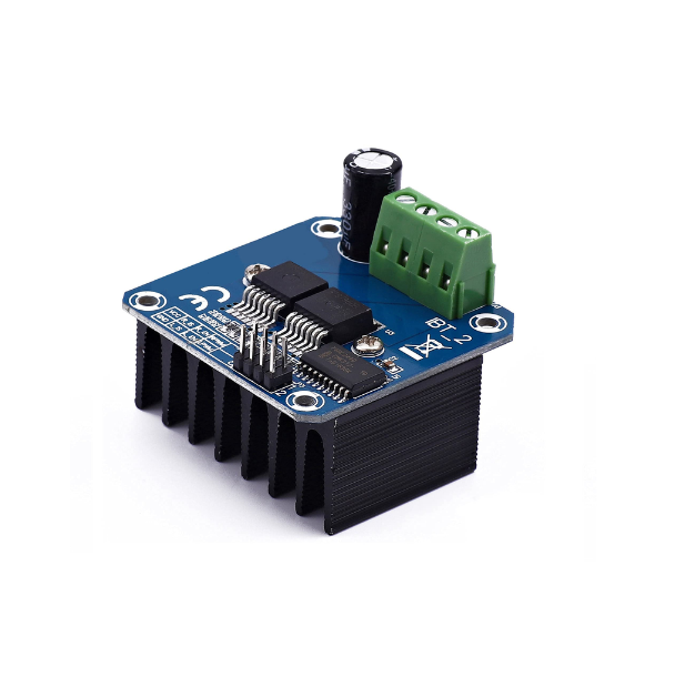 |
• Max Current: 43A • Operating Voltage: 6V–27V • Thermal Protection |
High-Current Motor Control | 11.1V Power Rail + ESP32 Logic PWM/DIR | Offers high current headroom, preventing thermal shutdown during heavy load or acceleration. |
| Hiwonder Digital Servo | 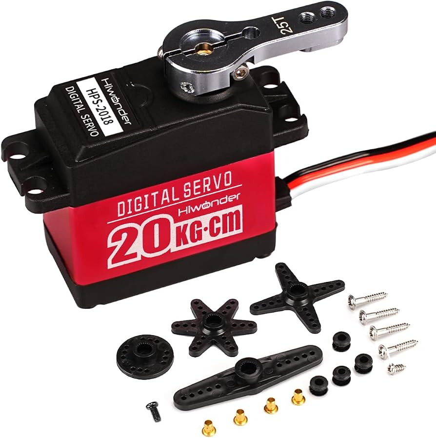 |
• Torque: 20 kg·cm • Metal Gears • Fast Response |
Steering Actuation | 6.5V Regulated Power Rail (PWM Control) | Metal gears and high torque ensure rigid steering alignment without mechanical backlash. |
| ESP32 Dev Board | 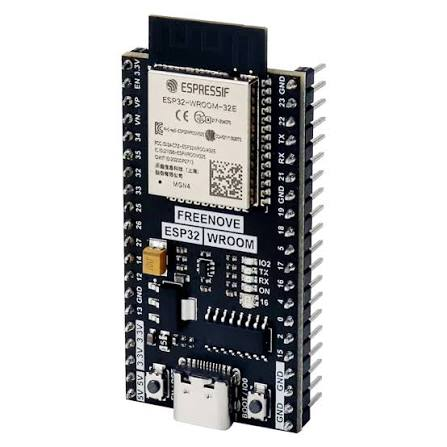 |
• Dual-Core 240MHz • Wi-Fi / Bluetooth • Hardware PWM |
Low-Level Microcontroller | 5V Regulated Logic Input (UART / I2C) | High processing speed for real-time encoder readings and PID motor loops. |
| BNO055 9-DOF IMU | 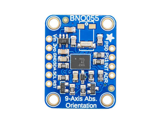 |
• Onboard Sensor Fusion • Absolute Orientation • Low Drift |
Orientation Feedback | ESP32 via I2C Bus | Built-in sensor fusion algorithm offloads IMU filtering from the main MCU. |
| Raspberry Pi 5 | 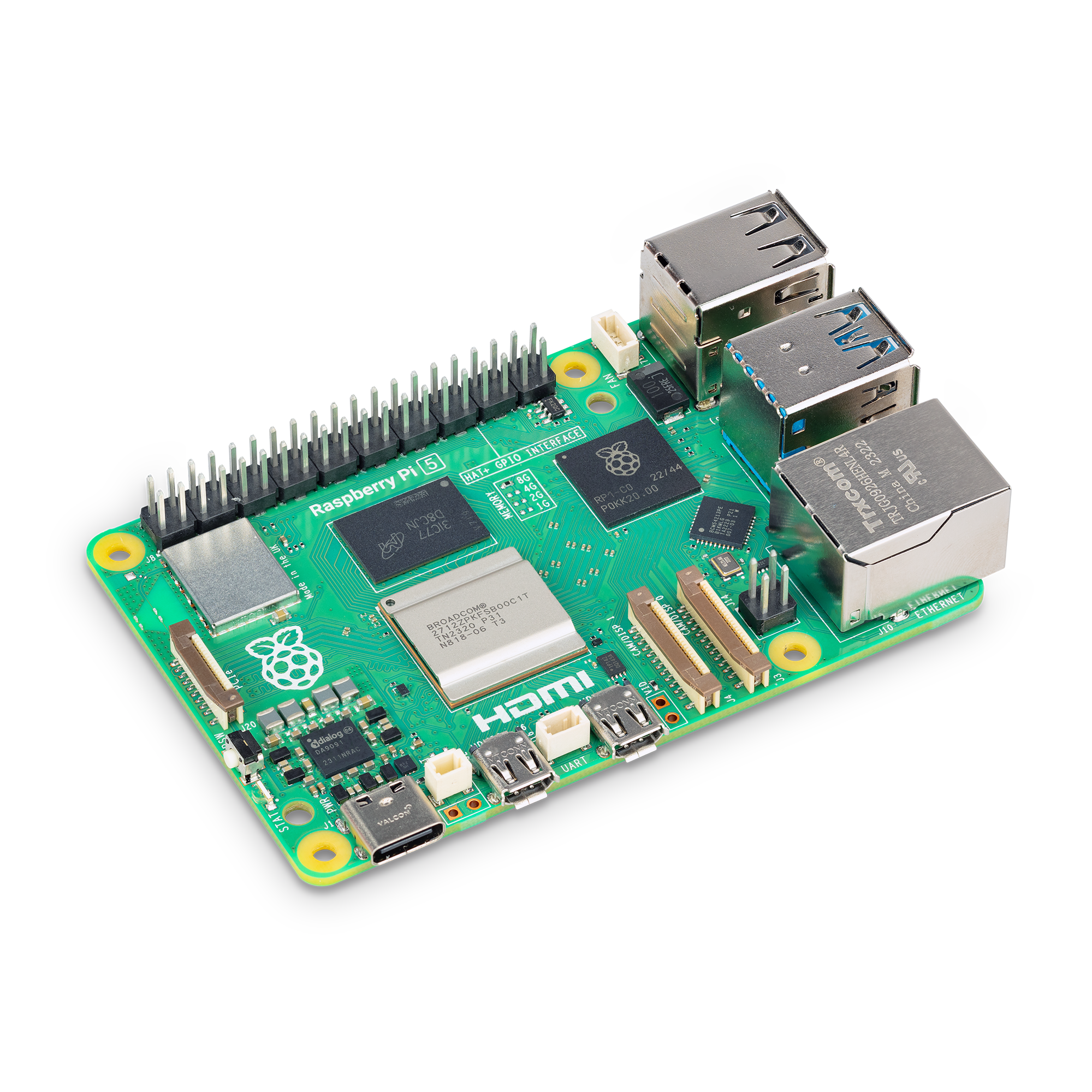 |
• Quad-Core ARM • 16GB RAM • USB 3.0 |
High-Level Vision Processing | 5V Regulated Logic Rail (USB/UART Interface) | Delivers high computational power and memory for real-time OpenCV image processing. |
| Logitech Brio 100 | 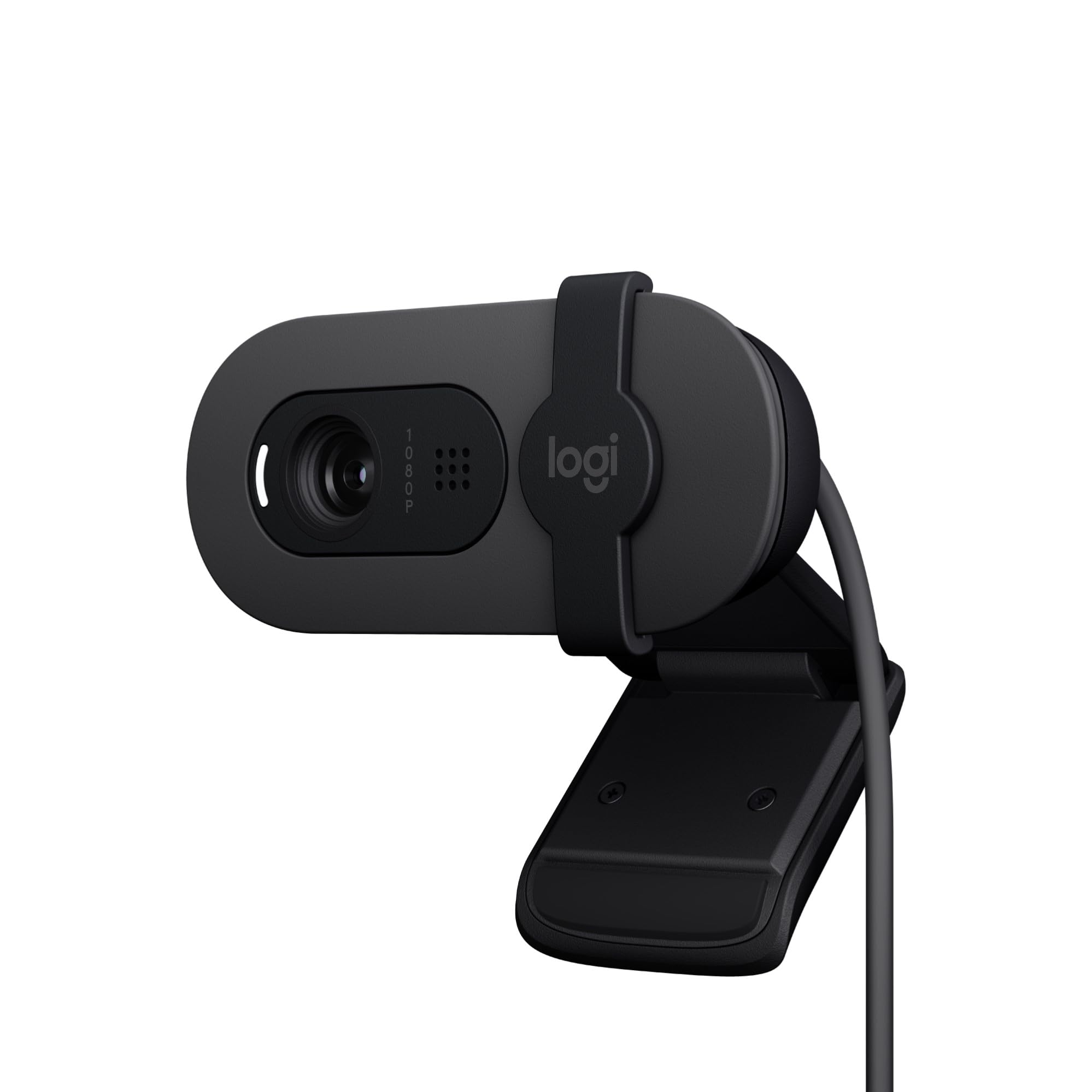 |
• 1080p Resolution • Wide FOV • Auto Light Balance |
Computer Vision Camera | USB Connection to Raspberry Pi 5 | Provides high clarity and stable frame rates across varying ambient light conditions. |
| XL4015 Buck Converters | 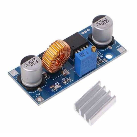 |
• Max Output: 5A / 50W • Adjustable Step-Down • High Efficiency (>90%) |
Power Step-Down (Logic & Servo) | Battery → Regulated Rails | Drives logic circuits and servos efficiently with low heat dissipation. |
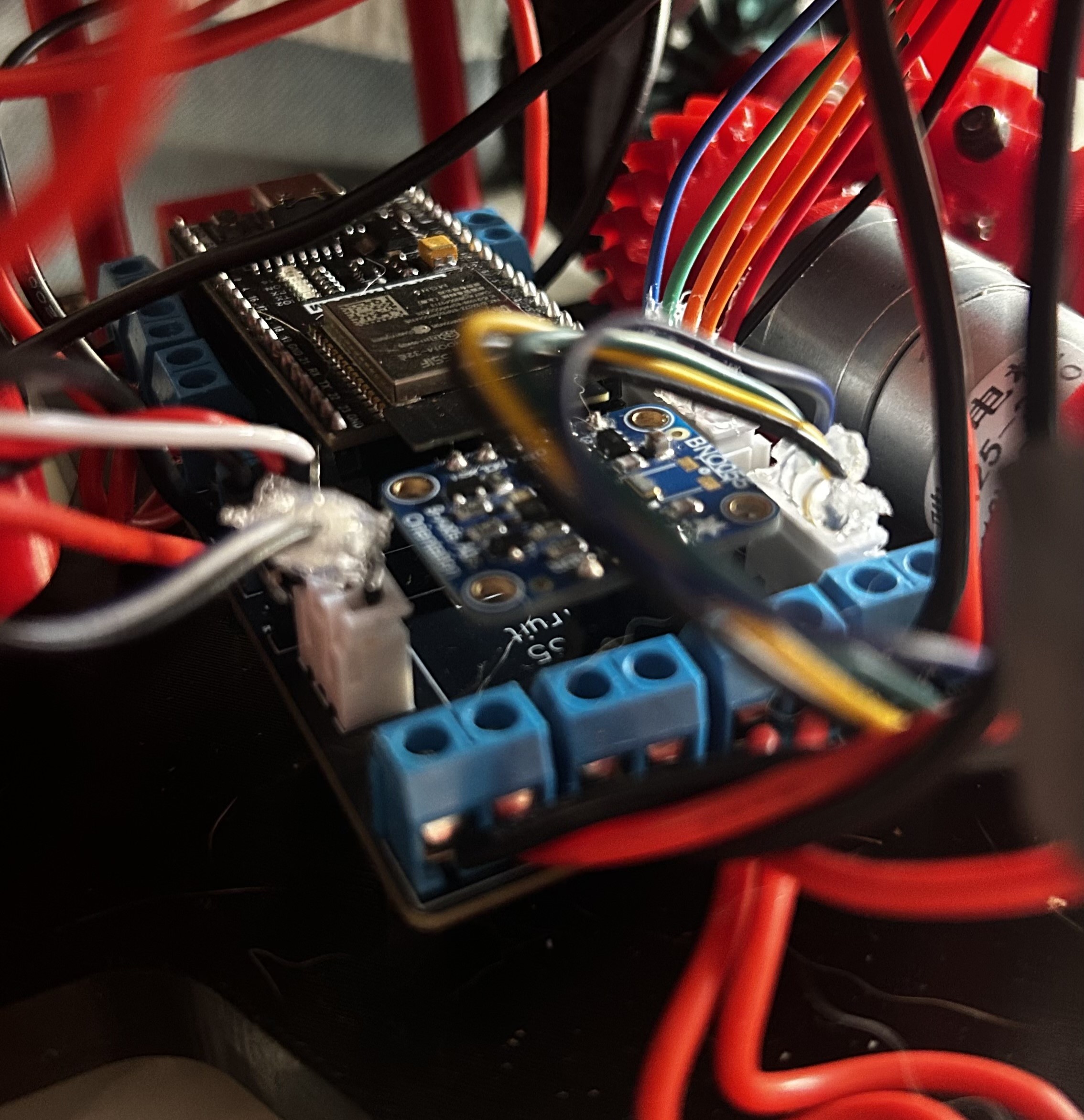
Final logic PCB physically mounted on the vehicle chassis.
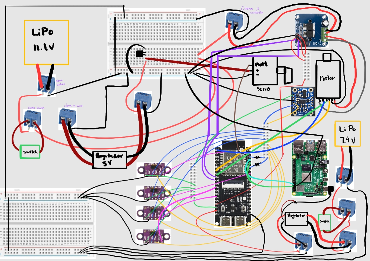
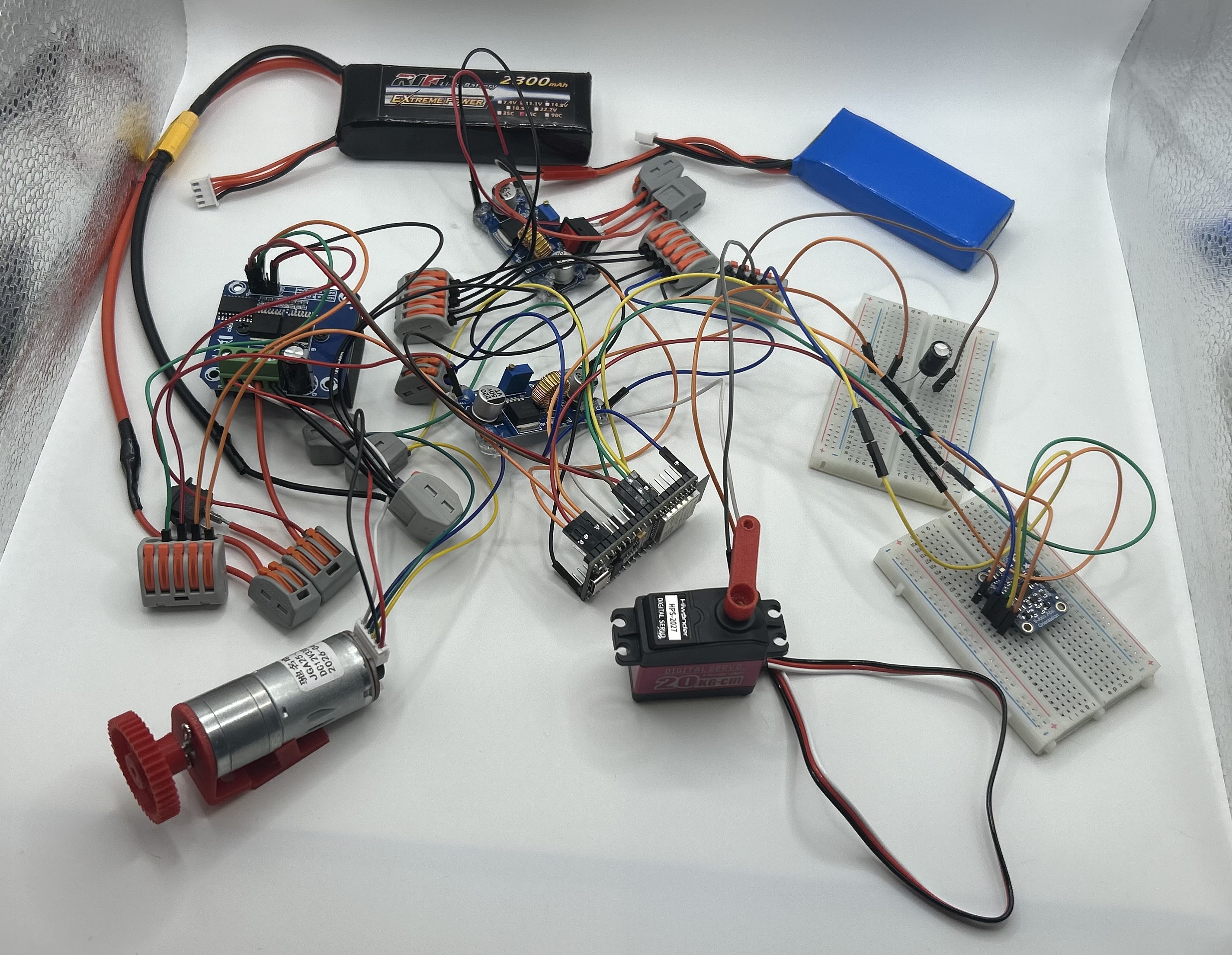
Left: Initial hand-drawn circuit mapping. Right: Breadboard logic validation before PCB design.
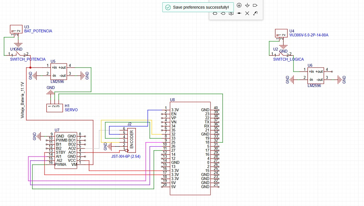
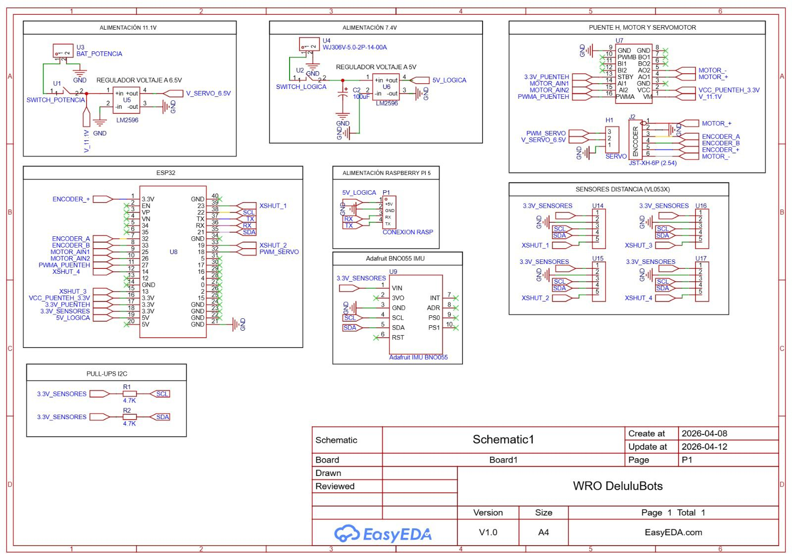
Earlier revisions of the system architecture (v1 and v2) during the prototyping phase.
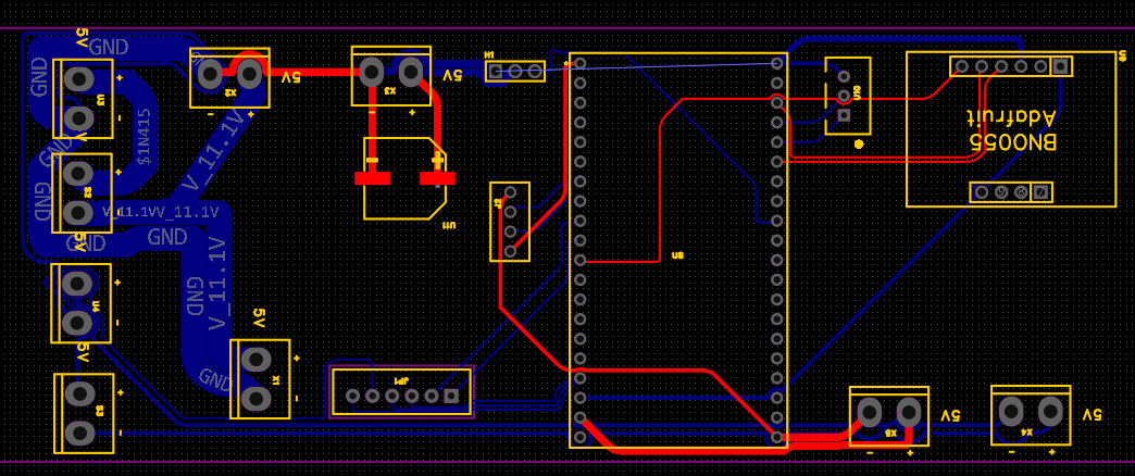
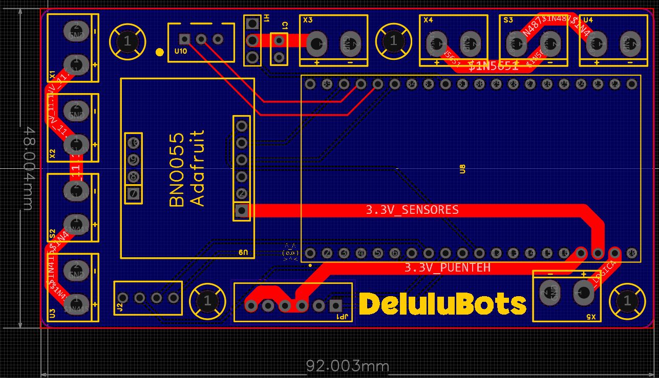
Left: Initial prototype board layout. Right: Final competition-ready custom PCB 3D model.