# Configuration Documentation for `esp32-c6-pv19-display.yaml`
This file provides a detailed description of the specialized ESPHome configuration for the **[Waveshare ESP32-C6-LCD-1.47](https://docs.waveshare.com/ESP32-C6-LCD-1.47)** board, used to monitor **Must PH19/PV19** solar hybrid inverters via the Modbus (RS485) protocol.
 ---
## External Connection Diagram (RS485 / Modbus)
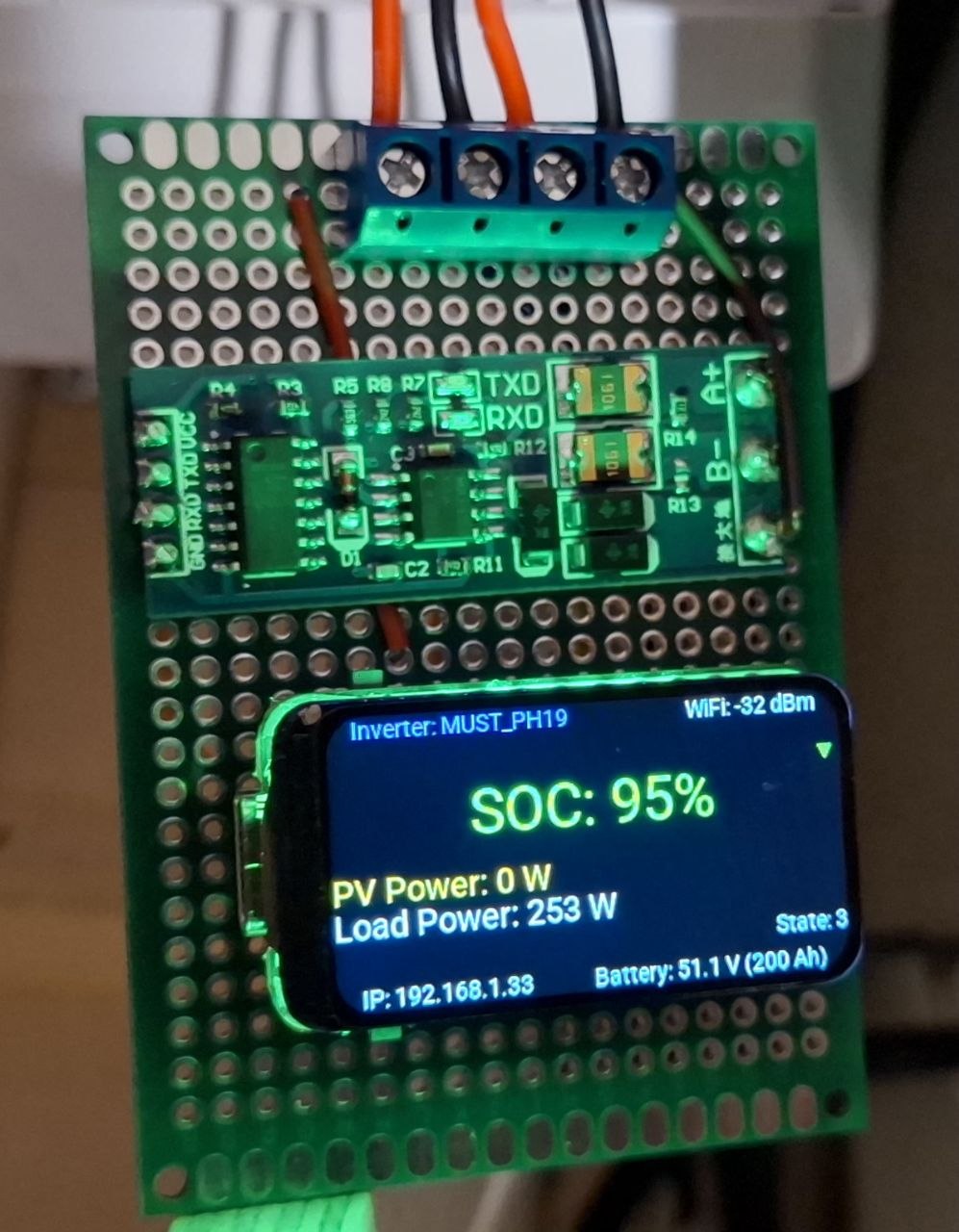
Since the display and LED are already integrated into the Waveshare ESP32-C6-LCD-1.47 board, you only need to connect an external **RS485 to UART** module to communicate with the inverter.
### Converter to Waveshare Board Pinout:
| Waveshare Board Pin | RS485 Converter Pin | Description |
| :--- | :--- | :--- |
| **3.3V** / **5V** | **VCC** | Converter power supply |
| **GND** | **GND** | Common ground (mandatory!) |
| **IO1 (GPIO1/TX)** | **RXD** | Modbus Data Transmission |
| **IO2 (GPIO2/RX)** | **TXD** | Modbus Data Reception |
> [!IMPORTANT]
> On this board, pins GPIO16/17 and GPIO12/13 are not suitable for Modbus due to internal hardware conflicts. Use only **IO1** and **IO2**.
### Connecting the Converter to the MUST Inverter:
You can connect the RS485 converter to the inverter in one of two ways, depending on your inverter model:
#### Option A: Via RJ45 Port (RS485 / CAN)
| RS485 Converter Pin | Inverter RJ45 Port Pin | Description |
| :--- | :--- | :--- |
| **A / TR+** | **PIN 1** / A | Signal Line A |
| **B / TR-** | **PIN 2** / B | Signal Line B |
| **GND** | **PIN 8** | RS485 Ground |
#### Option B: Via Wi-Fi Port (USB Type-A Connector)
> [!WARNING]
> This connector on the inverter is **not a standard USB port**. It does not provide USB data but carries +5V power lines and the RS485 bus. Do not connect standard USB devices to it!
To connect, use a regular USB Type-A cable, cutting one end to solder to the RS485 converter:
| USB Type-A Cable Pin | RS485 Converter Pin | Description |
| :--- | :--- | :--- |
| **Pin 1 (VCC)** | **5V / VCC** on ESP board | +5V power from inverter (optional) |
| **Pin 2 (D-)** | **B / TR-** | RS485-B Line |
| **Pin 3 (D+)** | **A / TR+** | RS485-A Line |
| **Pin 4 (GND)** | **GND** | Common Ground |
### Connection Diagram (Mermaid Diagram)
```mermaid
graph TD
subgraph "Waveshare ESP32-C6-LCD-1.47"
ESP_5V["5V / VCC"]
ESP_3V3["3.3V Out"]
GND1["GND"]
G1["GPIO1 (TX)"]
G2["GPIO2 (RX)"]
end
subgraph "RS485 to UART Module"
RS_VCC["VCC"]
RS_GND["GND"]
RS_RXD["RXD"]
RS_TXD["TXD"]
RS_A["A / TR+"]
RS_B["B / TR-"]
end
subgraph "MUST Inverter Port"
INV_VCC["VCC 5V (USB Pin 1)"]
INV_A["A / TR+ (RJ45 Pin 1 / USB Pin 3)"]
INV_B["B / TR- (RJ45 Pin 2 / USB Pin 2)"]
INV_GND["GND (RJ45 Pin 8 / USB Pin 4)"]
end
%% Power from Inverter to ESP32 (if using USB WiFi port)
INV_VCC -.->|Optional ESP Power| ESP_5V
%% RS485 Power & Data (from ESP32 to Converter)
ESP_3V3 --> RS_VCC
GND1 --> RS_GND
G1 --> RS_RXD
G2 --> RS_TXD
%% Modbus to Inverter
RS_A --- INV_A
RS_B --- INV_B
GND1 --- INV_GND
```
---
## Key Differences from the Original Repository
This configuration is a deep overhaul of the base project. Main improvements include:
### 1. Modern Hardware Support (ESP32-C6)
* **ESP-IDF Framework:** Unlike the original (Arduino), this version uses the professional ESP-IDF framework, ensuring stable UART operation and Wi-Fi 6 support.
* **Modbus Optimization:** Increased receive buffer (`rx_buffer_size: 4096`) and tuned delays (`command_throttle`, `send_wait_time`) specifically adapted for MUST inverters.
### 2. Local Monitoring (LCD Display)
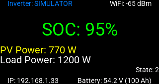
* **ST7789 Interface:** Real-time data output directly to the board's screen. You don't need to open Home Assistant to see key parameters:
* **SOC** (Battery Charge) in large font with color-coded status.
* Total solar panel output (**PV Power**).
* Household load (**Load Power**).
* Battery voltage and inverter work state.
### 3. Intelligent Indication (Smart LED)
* **Addressable LED:** The built-in WS2812 now acts as a system health indicator.
* **SOC Logic:** The LED changes color (Green/Yellow/Red) based on the battery charge level, with logic protected against invalid values (`nan`) during communication glitches.
### 4. Enhanced Reliability and Comfort
* **PWM Backlight:** Screen brightness is smoothly adjustable via Home Assistant and saved after a reboot.
* **Stability Tweaks:** Fine-tuned Modbus controller settings to minimize CRC errors in the EMI-heavy environment of the inverter.
---
## How to Build and Flash
1. Ensure your Wi-Fi passwords and API keys are filled in the `secrets.yaml` file.
2. Compile the firmware using the ESPHome CLI:
```bash
esphome compile esp32-c6-pv19-display.yaml
```
3. For the initial flash or recovery after a network failure, connect the board via USB and use [ESPHome Web Tools](https://web.esphome.io/), selecting the compiled file located at:
`.esphome/build//.pioenvs//firmware.factory.bin` (where `` is the value of the `name` substitution).
---
## External Connection Diagram (RS485 / Modbus)
Since the display and LED are already integrated into the Waveshare ESP32-C6-LCD-1.47 board, you only need to connect an external **RS485 to UART** module to communicate with the inverter.
### Converter to Waveshare Board Pinout:
| Waveshare Board Pin | RS485 Converter Pin | Description |
| :--- | :--- | :--- |
| **3.3V** / **5V** | **VCC** | Converter power supply |
| **GND** | **GND** | Common ground (mandatory!) |
| **IO1 (GPIO1/TX)** | **RXD** | Modbus Data Transmission |
| **IO2 (GPIO2/RX)** | **TXD** | Modbus Data Reception |
> [!IMPORTANT]
> On this board, pins GPIO16/17 and GPIO12/13 are not suitable for Modbus due to internal hardware conflicts. Use only **IO1** and **IO2**.
### Connecting the Converter to the MUST Inverter:
You can connect the RS485 converter to the inverter in one of two ways, depending on your inverter model:
#### Option A: Via RJ45 Port (RS485 / CAN)
| RS485 Converter Pin | Inverter RJ45 Port Pin | Description |
| :--- | :--- | :--- |
| **A / TR+** | **PIN 1** / A | Signal Line A |
| **B / TR-** | **PIN 2** / B | Signal Line B |
| **GND** | **PIN 8** | RS485 Ground |
#### Option B: Via Wi-Fi Port (USB Type-A Connector)
> [!WARNING]
> This connector on the inverter is **not a standard USB port**. It does not provide USB data but carries +5V power lines and the RS485 bus. Do not connect standard USB devices to it!
To connect, use a regular USB Type-A cable, cutting one end to solder to the RS485 converter:
| USB Type-A Cable Pin | RS485 Converter Pin | Description |
| :--- | :--- | :--- |
| **Pin 1 (VCC)** | **5V / VCC** on ESP board | +5V power from inverter (optional) |
| **Pin 2 (D-)** | **B / TR-** | RS485-B Line |
| **Pin 3 (D+)** | **A / TR+** | RS485-A Line |
| **Pin 4 (GND)** | **GND** | Common Ground |
### Connection Diagram (Mermaid Diagram)
```mermaid
graph TD
subgraph "Waveshare ESP32-C6-LCD-1.47"
ESP_5V["5V / VCC"]
ESP_3V3["3.3V Out"]
GND1["GND"]
G1["GPIO1 (TX)"]
G2["GPIO2 (RX)"]
end
subgraph "RS485 to UART Module"
RS_VCC["VCC"]
RS_GND["GND"]
RS_RXD["RXD"]
RS_TXD["TXD"]
RS_A["A / TR+"]
RS_B["B / TR-"]
end
subgraph "MUST Inverter Port"
INV_VCC["VCC 5V (USB Pin 1)"]
INV_A["A / TR+ (RJ45 Pin 1 / USB Pin 3)"]
INV_B["B / TR- (RJ45 Pin 2 / USB Pin 2)"]
INV_GND["GND (RJ45 Pin 8 / USB Pin 4)"]
end
%% Power from Inverter to ESP32 (if using USB WiFi port)
INV_VCC -.->|Optional ESP Power| ESP_5V
%% RS485 Power & Data (from ESP32 to Converter)
ESP_3V3 --> RS_VCC
GND1 --> RS_GND
G1 --> RS_RXD
G2 --> RS_TXD
%% Modbus to Inverter
RS_A --- INV_A
RS_B --- INV_B
GND1 --- INV_GND
```
---
## Key Differences from the Original Repository
This configuration is a deep overhaul of the base project. Main improvements include:
### 1. Modern Hardware Support (ESP32-C6)
* **ESP-IDF Framework:** Unlike the original (Arduino), this version uses the professional ESP-IDF framework, ensuring stable UART operation and Wi-Fi 6 support.
* **Modbus Optimization:** Increased receive buffer (`rx_buffer_size: 4096`) and tuned delays (`command_throttle`, `send_wait_time`) specifically adapted for MUST inverters.
### 2. Local Monitoring (LCD Display)
* **ST7789 Interface:** Real-time data output directly to the board's screen. You don't need to open Home Assistant to see key parameters:
* **SOC** (Battery Charge) in large font with color-coded status.
* Total solar panel output (**PV Power**).
* Household load (**Load Power**).
* Battery voltage and inverter work state.
### 3. Intelligent Indication (Smart LED)
* **Addressable LED:** The built-in WS2812 now acts as a system health indicator.
* **SOC Logic:** The LED changes color (Green/Yellow/Red) based on the battery charge level, with logic protected against invalid values (`nan`) during communication glitches.
### 4. Enhanced Reliability and Comfort
* **PWM Backlight:** Screen brightness is smoothly adjustable via Home Assistant and saved after a reboot.
* **Stability Tweaks:** Fine-tuned Modbus controller settings to minimize CRC errors in the EMI-heavy environment of the inverter.
---
## How to Build and Flash
1. Ensure your Wi-Fi passwords and API keys are filled in the `secrets.yaml` file.
2. Compile the firmware using the ESPHome CLI:
```bash
esphome compile esp32-c6-pv19-display.yaml
```
3. For the initial flash or recovery after a network failure, connect the board via USB and use [ESPHome Web Tools](https://web.esphome.io/), selecting the compiled file located at:
`.esphome/build//.pioenvs//firmware.factory.bin` (where `` is the value of the `name` substitution).