# 3D Graphics Part 3: Scan conversion and shading
## CSCI 315
What we know so far:
- Rasterization is the process of turning objects into pixels.
- The 3D graphics pipeline begins with the geometrics primitives in a scene. The output is a color for each pixel on the screen(s).
- 3D objects are typically modelled using 2D polygons, usually triangles. Each point on the corner of a polygon is a vertex. The coordinates and order of the vertices are all that is needed to recreate the shape.
The pipeline steps we have discussed so far are:
1. Modeling and transformation
2. Camera transformation
3. Lighting (not really)
4. Projection transformation
5. Clipping and culling
At this point we have translated our 3D objects into a much smaller set of 2D objects. We have retained the z-coordinate (y in Unreal) for use in the next steps, namely:
6. Scan conversion (rasterization)
7. Texturing and fragment shading
The end result will be a color value for each pixel in the rendered scene.
## Scan conversion (rasterization)
The goal of scan conversion is to rasterize our 2D objects into pixels.The first step is to transform our coordinates from world space to screen space, a process called *viewport transformation*. The camera projection gave us a set of 2D objects in world units. The other piece of information we need is the target rectangle (width, height, and origin) in pixels. This target rectangle is known as the *viewport*. When the viewport occupies the entire screen (or window), the origin is (0,0) and can be ignored in the calculation.
We can illustrate this process for a line using an algorithm that is simple, but too costly to use in practice.
Given a line segment from leftmost `(X0 ,Y0)` to rightmost `(X1,Y1)`:
``` math
Y = mX + B
m = deltaY / deltaX = (Y1 - Y0) / ( X1 - Xo)
```
Assuming `|m| <= 1` we start at the leftmost edge of the line, and move right one pixel-column at a time illuminating the appropriate pixel in that column.
``` math
start = round(X0)
stop = round(X1)
for (Xi = start; Xi <= stop; Xi++)
illuminate Xi, round(m * Xi + B);
```
Why is this inefficient? Each iteration includes:
- comparison
- fractional multiplication
- 2 additions
- a call to round()
Addition is acceptable, floating point multiplication is bad, and a function call is very bad as this is done many times for *every frame* . We need more complex algorithms which use simpler operations to decrease the speed. Happily, several more efficient algorithms exist.
In addition to calculating pixel values for each point and line, the scan conversion process also must interpolate pixel values for the surfaces inside the polygons.
Note that the transformation algorithm determines which pixels to *illuminate*, without really specifying what this means. The (mostly) final step in the rendering pipeline is to determine exactly what color each pixel will take. For a simple black and white image, this is simply determining whether a pixel is "on" or "off". More complex image rendering requires us to determine a color for and filled pixel.
## Lighting
I told you we would come back to this one. We know that the color of an object we see is generally the *reflected* color from its surface. (We will deal with objects that bring their own light shortly.) This reflected color is a combination of the material on the surface of the object and the light that strikes it. Traditionally, the color information for vertices is computed during the camera view transformation. This information is used to color the fill pixels of the object, a process known as *shading*. Physically based rendering (PBR) methods are changing this process somewhat.
## Shading
The color that enters the camera (i.e., your eye) from a specific pixel is a function of three factors: the material on the object, the light that strikes the material, and the angle of reflectance between the light and the camera. We can view one part of pixel shading as computing the bidirectional reflectance distribution function (BRDF) for a material. The BRDF is a function that characterizes how color reflects from a surface at different angles. We use the BRDF to fill in the polygon surfaces between the vertices.
### Flat Shading
With flat shading we color each triangle the same across its entire surface. To do this, we calculate the BDRF at a single point --
usually the center of the triangle -- usually at the center of the triangle -- and use that value for each pixel in the triangle.
This technique is easy, but does not look particularly good. The coloring accentuates the fact that objects are made of polygons. It is okay for flat surfaces, but not good at all for smooth or rounded objects.
### Gouraud Shading
Gouraud shading improves on flat shading by computing the BRDF at each vertex and interpolating colors between the vertices. The method of interpolation used can impact the appearance and efficiency of this technique. In addition, it computes a normal at each vertex that averages the normals of adjoining polygons, which helps to smooth the appearance of rounded surfaces.
The primary issue with Gouraud shading is that is requires a relatively dense mesh to capture subtle lighting effects. This is especially apparent with reflective materials.
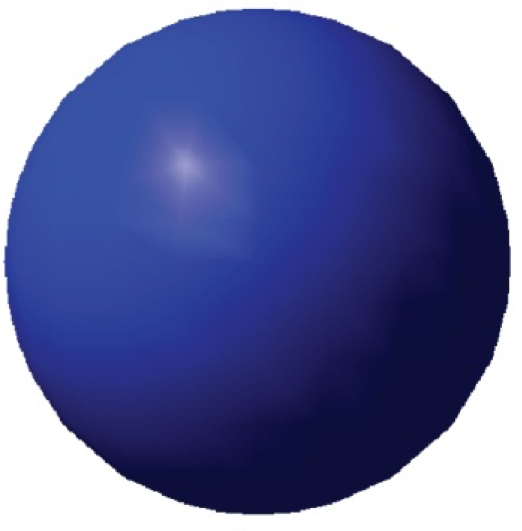
Object drawn with Gouraud shading.
### Phong Shading (not the same thing as Phong reflection model!)
Phong shading improves on Gouraud by interpolating vertex normals between vertices. In other words, it will compute BRDF at every pixel, using an interpolated normal value.
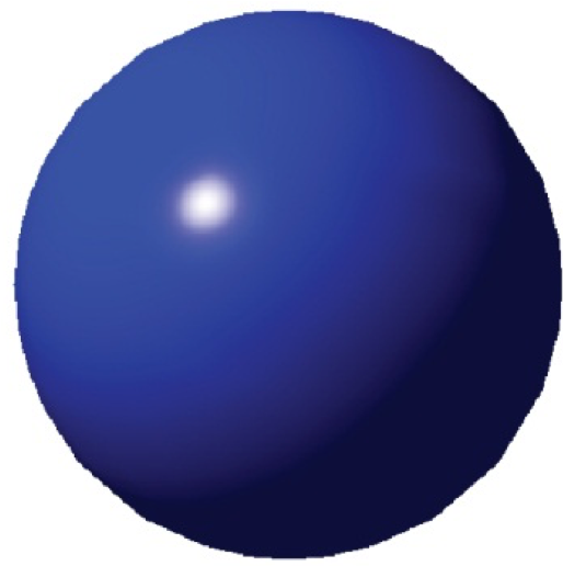
Object drawn with Phong shading.
### Drawbacks of interpolated shading
The techniques here share a number of potential issues:
- the silhouettes of the polygons are still obvious when viewed closely.
- perspective can distort the colors, since interpolations are performed in screen space -- not model space.
- there can be problem computing shared vertex normals, especially those with sharp angles.
The development of powerful graphics processing units (GPUs) have enabled the use of shading and post-processing techniques to greatly reduce or eliminate these issues.
## Depth Testing: Determining Visibility
We have computed a color for each pixel representing each object in the scene, but suppose two objects map to the same pixel. It is important to be able to determine which will be visible. Clipping and culling are based on the scene geometry and the properties of individual objects. *Depth testing* ensures that objects closer to the viewer are drawn in front of those farther away.
Perhaps the simplest way to achieve this is to use the *painter's algorithm*. The painter's algorithm sorts scene objects by distance from the viewer, and draws them in descending order. Nearer objects are drawn over objects that are farther away.
The painter's algorithm has a lot of overdraw — redrawing the same pixel multiple times per frame. To use it in 3D scenes, we would have to sort every triangle back to front.
To make things worse, the camera is dynamic, so we would have to re-sort every frame!
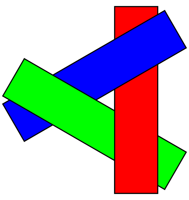
Worse yet, the painter's algorithm can fail to draw the scene correctly. For example, there is a possibility in 3D that no one triangle is the furthest back.
The painter's algorithm can fail in 3D scenes when polygons overap.
[Image by Wojciech Muta](https://commons.wikimedia.org/w/index.php?curid=3651919)
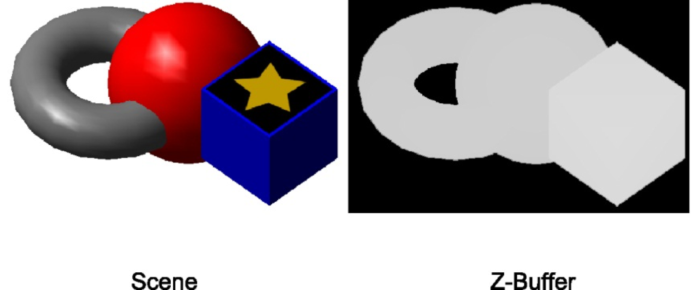
One popular way to avoid the pitfalls of the painter's algorithm is to use **z-buffering**.
We create a new screen-sized buffer called the z-buffer. It stores the depth of every pixel that is drawn.
As we draw pixels in the scene, we only draw it if the depth stored in the z-buffer is greater than the depth of the current pixel.

A sample scene and its corresponding z-buffer..
#### Z-Buffering Pseudocode
``` javascript
// zBuffer[x][y] grabs depth at that pixel
foreach Object o in scene
foreach Pixel p in o
float depth = calculate depth at p
if zBuffer[p.x][p.y] > depth
draw p
zBuffer[p.x][p.y] = depth
end
end
end
```
Some objects may not be written to the z-buffer. For example, we will want to render objects that appear behind transparent objects, so we might choose not write the latter to the z-buffer.
## References
[Unity Manual: Culling and Depth Testing](https://docs.unity3d.com/Manual/SL-CullAndDepth.html)
[Intro to Computer Graphics, J. Bell, University of Illinois Chicago](https://www.cs.uic.edu/~jbell/CourseNotes/ComputerGraphics/ScanConversion.html)