**NOTE: If you have FlashFloppy installed on your Gotek, you do not
need to follow these steps.** Instead perform a [Firmware
Update](Firmware-Update).
**NOTE: Disconnect your Gotek's power and data cables before
programming.** The only connection should be to your programming host
via serial adapter or USB.
The firmware programming process depends on which
[type of microcontroller](Gotek-Models#microcontroller-options)
is inside your Gotek: [Artery](#artery-microcontrollers), or
[STM32](#stm32-microcontrollers).
## Artery Microcontrollers
To flash the Gotek you will need a special USB cable with USB-A
connectors on both ends. If your host has only USB-C ports then a
USB-C to USB-A cable *may* work but it is not expected that the USB-C
port will provide power to such a cable; be prepared instead
to attach an aforementioned USB-A-to-A cable via a hub.
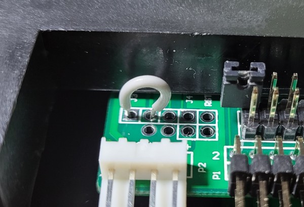
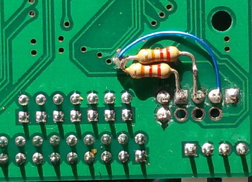
Before connecting the USB cable you need to strap the Boot
jumper to enter programming mode. As the jumper pins are not
installed by default, you may need to use a wire to short the two
leftmost pads on the programming header:
 The following instructions are for Windows. If you wish to program the
firmware on Linux, see the [conclusion of #698][linux-art-prg].
Download the ISP drivers and programming utility from the [Artery
website][artery-isp] via the **Program and Debug** -> **ISP Programmer** download
link.
Unpack the archive and install the
drivers by running the file **Artery_DFU_DriverInstall.exe** from the
**Artery_DFU_DriverInstall** folder. After the drivers are installed,
connect the Gotek via USB and run the programming utility
**ArteryISPProgrammer.exe** from the **Artery ISP Programmer**
folder. Microsoft Defender may warn that the application is unrecognised:
Select **More info** and **Run anyway**.
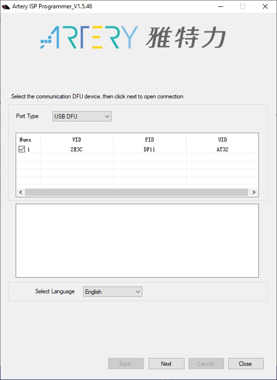
Once started, if the initial screen is in Chinese, select **English**
from the lower tab. Now select **USB DFU** for the Port Type
and check that the Gotek has been found:
The following instructions are for Windows. If you wish to program the
firmware on Linux, see the [conclusion of #698][linux-art-prg].
Download the ISP drivers and programming utility from the [Artery
website][artery-isp] via the **Program and Debug** -> **ISP Programmer** download
link.
Unpack the archive and install the
drivers by running the file **Artery_DFU_DriverInstall.exe** from the
**Artery_DFU_DriverInstall** folder. After the drivers are installed,
connect the Gotek via USB and run the programming utility
**ArteryISPProgrammer.exe** from the **Artery ISP Programmer**
folder. Microsoft Defender may warn that the application is unrecognised:
Select **More info** and **Run anyway**.
Once started, if the initial screen is in Chinese, select **English**
from the lower tab. Now select **USB DFU** for the Port Type
and check that the Gotek has been found:
 Click the **Next** button until you get to a screen with many options:
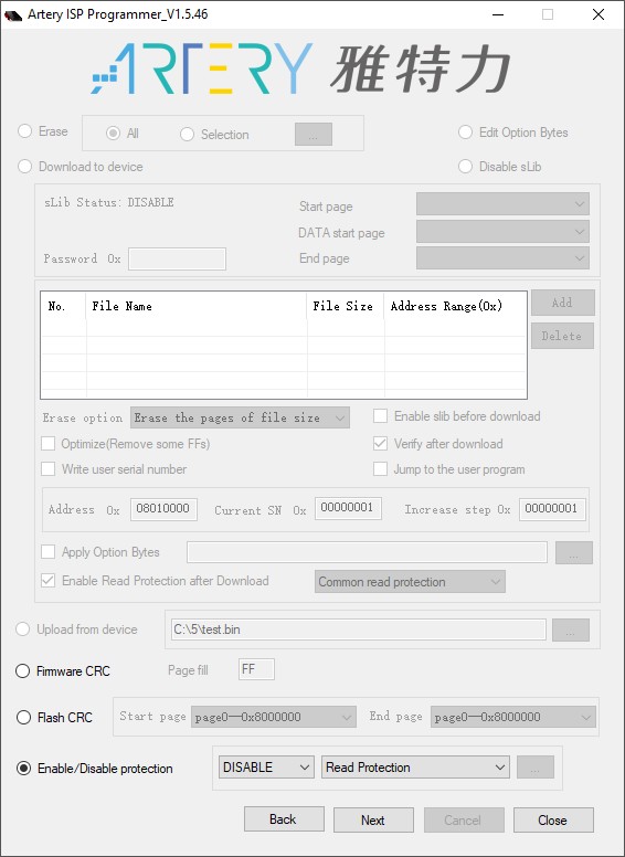 Now we need to erase the old firmware and disable Flash protection. Select the
**Enable/Disable Protection** option and click **Next**. A warning will be
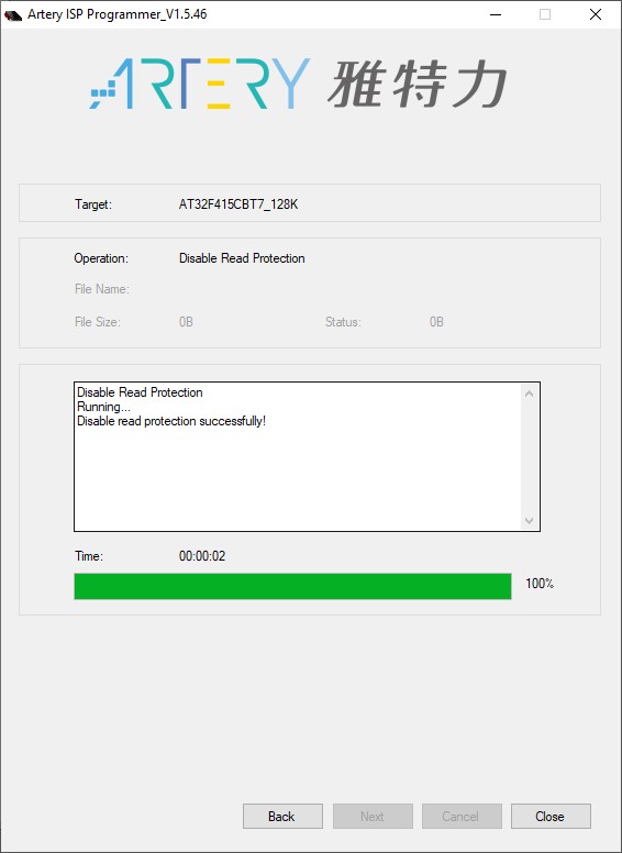
shown about completely erasing the flash memory. Click **Yes**. In the new
window you will see the process of flash memory erasing and the
results. If everything goes well, the interface will look like this:
Now we need to erase the old firmware and disable Flash protection. Select the
**Enable/Disable Protection** option and click **Next**. A warning will be
shown about completely erasing the flash memory. Click **Yes**. In the new
window you will see the process of flash memory erasing and the
results. If everything goes well, the interface will look like this:
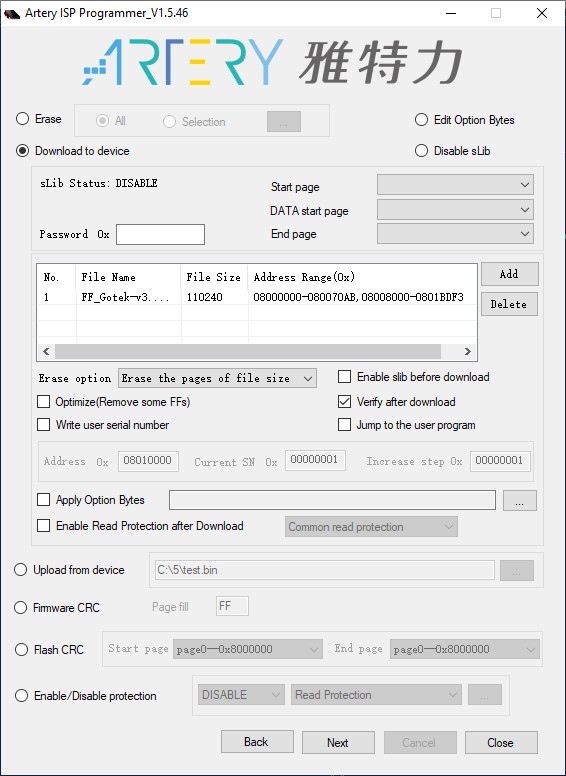
 Click **Back** and choose **Download to device**. Then click **Add** and select
the appropriate HEX file from the Flashfloppy release archive (`3.38`
can be replaced by the latest version):
* AT32F415 MCU: `flashfloppy-at415-st105-3.38.hex`
* AT32F435 MCU: `flashfloppy-at435-3.38.hex`
Optionally select the **Verify after download** option. Do not
enable any read or write protections! The interface should now look
like this:
Click **Back** and choose **Download to device**. Then click **Add** and select
the appropriate HEX file from the Flashfloppy release archive (`3.38`
can be replaced by the latest version):
* AT32F415 MCU: `flashfloppy-at415-st105-3.38.hex`
* AT32F435 MCU: `flashfloppy-at435-3.38.hex`
Optionally select the **Verify after download** option. Do not
enable any read or write protections! The interface should now look
like this:
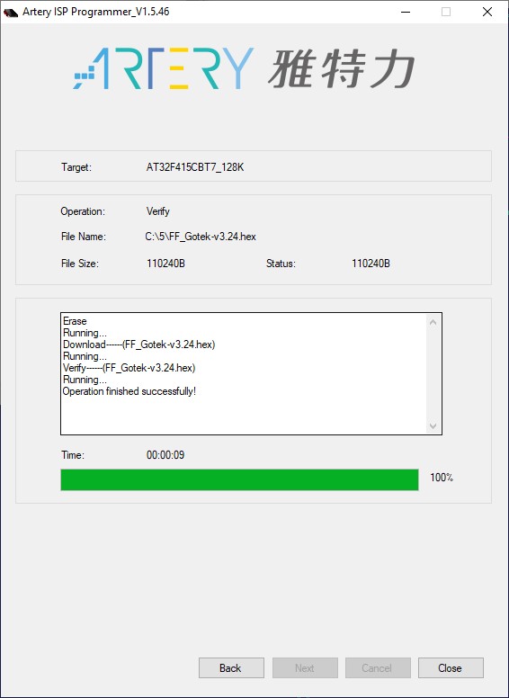
 Check everything and click **Next**. There will be another warning about
your firmware being unsafe if you don't enable the read
protection. Just ignore it and click **Ok**. In the new window you
will see the flashing and verification process and the result of the
firmware upload. If everything goes well, the interface will look like
this:
Check everything and click **Next**. There will be another warning about
your firmware being unsafe if you don't enable the read
protection. Just ignore it and click **Ok**. In the new window you
will see the flashing and verification process and the result of the
firmware upload. If everything goes well, the interface will look like
this:
 Programming is complete: You can disconnect the Gotek and remove the
programming jumper.
## STM32 Microcontrollers
### STM32 Method 1: USB Programming
This method requires a suitable USB cable, a pair of jumper wires to
configure the programming header of the Gotek, and the ***.dfu**
programming file contained in the FlashFloppy distribution.
You will require a USB-A to USB-A cable, or USB-C to USB-A if your host
has a USB-C port.
#### USB Programming Setup
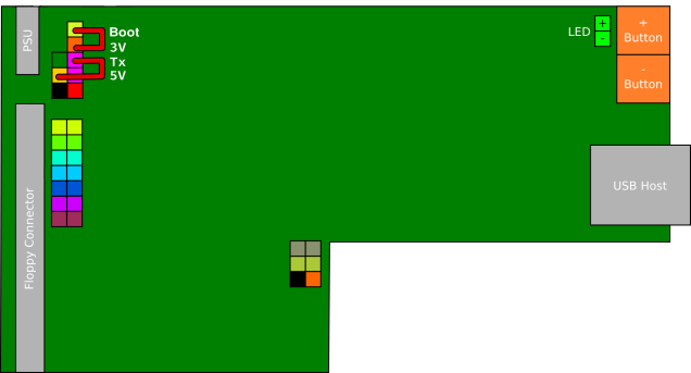
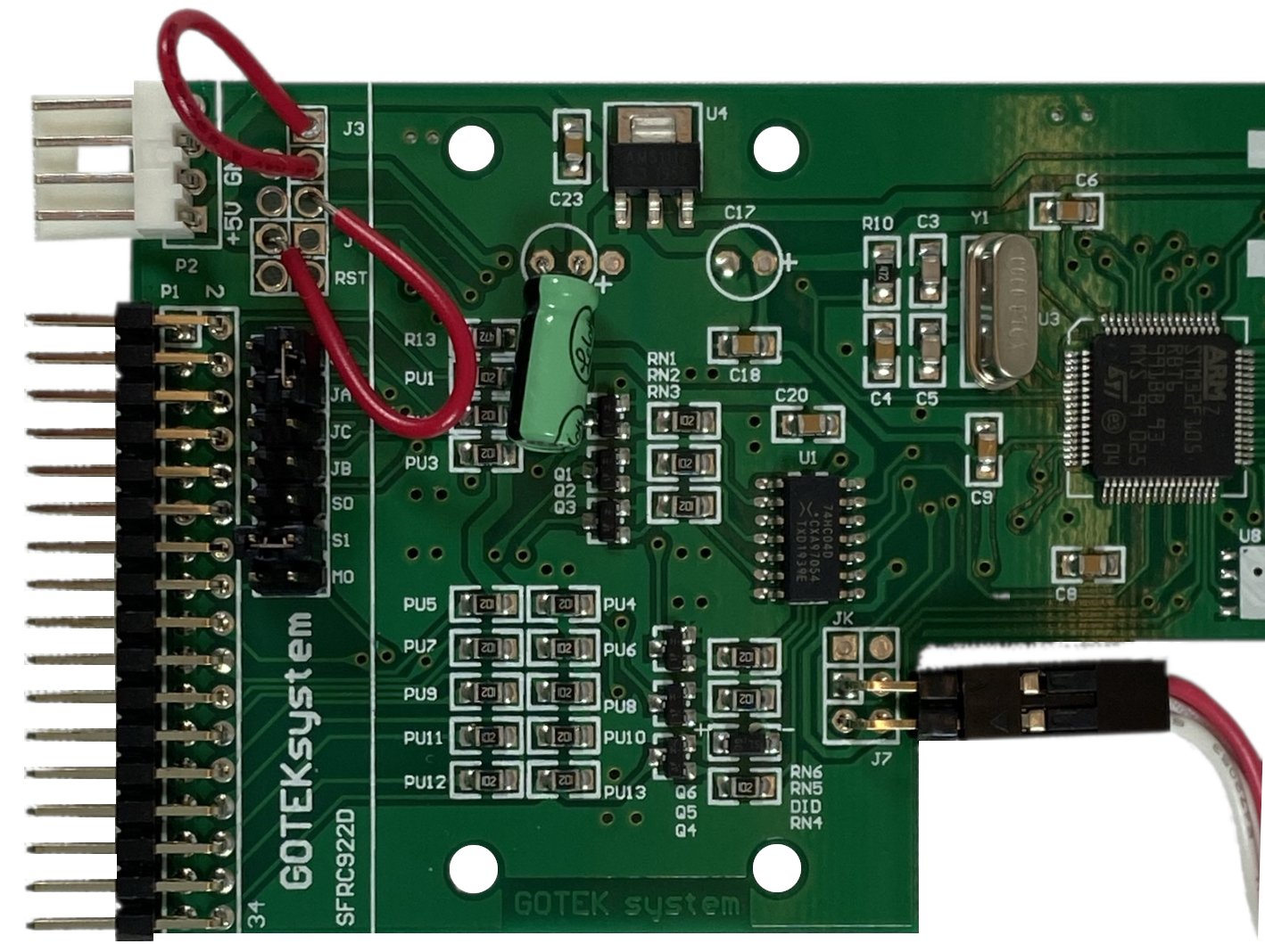
To configure the programming header of the Gotek, temporarily place
jumper wires across the following pin pairs: **Boot**-**3V** and
**Tx**-**5V**.
Because these jumper wires are temporary and only used for this
initial programming, you can simply use short lengths of hookup
wire. In doing so, ensure the exposed ends of your wires are not
touching each other.
Programming is complete: You can disconnect the Gotek and remove the
programming jumper.
## STM32 Microcontrollers
### STM32 Method 1: USB Programming
This method requires a suitable USB cable, a pair of jumper wires to
configure the programming header of the Gotek, and the ***.dfu**
programming file contained in the FlashFloppy distribution.
You will require a USB-A to USB-A cable, or USB-C to USB-A if your host
has a USB-C port.
#### USB Programming Setup
To configure the programming header of the Gotek, temporarily place
jumper wires across the following pin pairs: **Boot**-**3V** and
**Tx**-**5V**.
Because these jumper wires are temporary and only used for this
initial programming, you can simply use short lengths of hookup
wire. In doing so, ensure the exposed ends of your wires are not
touching each other.
 #### Windows
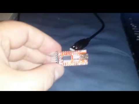
For more details watch the following Youtube video. **Note:** The
required **flashfloppy-at415-st105-\.dfu** file is now included
in the FlashFloppy distribution; there is no need to create it from
the ***.hex** file and those steps can be skipped.
[](http://www.youtube.com/watch?v=yUOyZB9cro4 "Flash Gotek without Serial Adapter")
#### Linux / Mac
Firstly, set the programming jumpers as described above, and detailed in the Windows tutorial
video. Ignore the rest of the video, which is Windows-specific.
Connect the Gotek to your host using a suitable USB cable.
Programming requires the `dfu-util` command-line tool which can be
downloaded via your package manager (Linux), or Homebrew (on
macOS). Programming is then as simple as (for v3.23 in this example):
```
sudo dfu-util -a 0 -s :unprotect:force -D dfu/flashfloppy-at415-st105-3.38.dfu
sudo dfu-util -a 0 -D dfu/flashfloppy-at415-st105-3.38.dfu
```
The first line is only needed if the Gotek Flash is read-protected (this
is the case for factory-fresh Goteks). Since the `unprotect` command resets
the Gotek, you may need to wait some seconds before issuing the second
command, while the DFU device is re-enumerated.
There are reports of some issues connecting as a DFU device to
macOS. In some cases this can be solved by connecting via an external
USB hub.
[an2606]: http://www.st.com/resource/en/application_note/cd00167594.pdf
### STM32 Method 2: Serial Programming
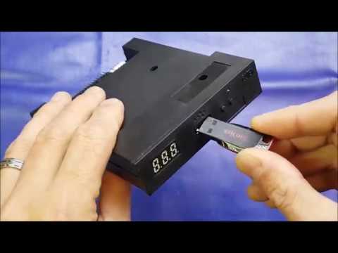
A nice video summary of this method using programming software on
Windows is available on Youtube courtesy of Kris Cochrane. It also
includes the [OLED Display](Hardware-Mods#oled-display) and
[Piezo Sounder](Hardware-Mods#speaker) mods:
[](http://www.youtube.com/watch?v=-K31S2xqZIk "FlashFloppy custom firmware install")
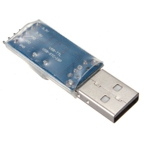
Serial programming requires a USB-TTL adapter, readily available on
Ebay or from project webstores:
- [CAB-12977 from SparkFun](https://www.sparkfun.com/products/12977)
- Search "PL2303HX usb ttl adapter" on Ebay, available for around one dollar.
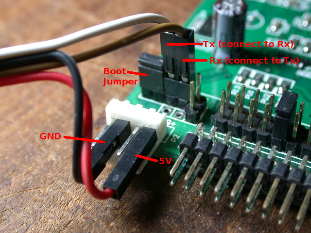
The Gotek is then jumpered in system-bootloader mode and programmed
from the host PC. See the below picture for wiring and jumper
selection.
**Important Notes:**
- Your Gotek may have a different number of header pins/holes, but any
missing or extra pins are not used in the programming process.
- This Gotek has pins soldered to the programming header. It is possible
to make the connections with no soldering, but take care that all wires
are sufficiently well connected.
- The ordering of the connections (5V,GND,TX,RX) can vary across
USB-TTL serial adapters, so be careful to note the ordering on your
own.
The programming process is described, along with suitable
Windows software, on the
[Cortex firmware webpage](https://cortexamigafloppydrive.wordpress.com).
Of course, rather than using the Cortex HEX file, use the ***.hex** file
contained in the FlashFloppy distribution.
If programming on Linux, you can follow the Cortex instructions to
physically set up your serial connection and bootstrap the Gotek, and
then use stm32flash to do the programming (for v0.10 in this example):
```
# sudo stm32flash -k /dev/ttyUSB0
# sudo stm32flash -vw hex/flashfloppy-at415-st105-3.38.hex /dev/ttyUSB0
```
#### Troubleshooting
- On Windows, ensure the driver has correctly detected the USB-TTL
adapter. In particular, PL2303 clones have trouble with the official
Prolific driver.
- Ensure you have TX and RX wires the correct way round.
- Sometimes the STM32 bootloader gets confused or negotiates the wrong
baud rate. Try resetting the Gotek by touching NRST to GND, or
by removing and reapplying power.
- Some serial adapters require pull-up resistors on the TX and RX
wires. See [AN2606 ("STM32 microcontroller system memory boot
mode")][an2606], Section 3.3, Figure 1. A suitable resistor value
(R) is 10K; these can safely be connected to VCC/+V of 3.3V or 5V.
[artery-isp]: https://www.arterychip.com/en/support/tools.jsp
[linux-art-prg]: https://github.com/keirf/flashfloppy/discussions/698#discussioncomment-3901428
#### Windows
For more details watch the following Youtube video. **Note:** The
required **flashfloppy-at415-st105-\.dfu** file is now included
in the FlashFloppy distribution; there is no need to create it from
the ***.hex** file and those steps can be skipped.
[](http://www.youtube.com/watch?v=yUOyZB9cro4 "Flash Gotek without Serial Adapter")
#### Linux / Mac
Firstly, set the programming jumpers as described above, and detailed in the Windows tutorial
video. Ignore the rest of the video, which is Windows-specific.
Connect the Gotek to your host using a suitable USB cable.
Programming requires the `dfu-util` command-line tool which can be
downloaded via your package manager (Linux), or Homebrew (on
macOS). Programming is then as simple as (for v3.23 in this example):
```
sudo dfu-util -a 0 -s :unprotect:force -D dfu/flashfloppy-at415-st105-3.38.dfu
sudo dfu-util -a 0 -D dfu/flashfloppy-at415-st105-3.38.dfu
```
The first line is only needed if the Gotek Flash is read-protected (this
is the case for factory-fresh Goteks). Since the `unprotect` command resets
the Gotek, you may need to wait some seconds before issuing the second
command, while the DFU device is re-enumerated.
There are reports of some issues connecting as a DFU device to
macOS. In some cases this can be solved by connecting via an external
USB hub.
[an2606]: http://www.st.com/resource/en/application_note/cd00167594.pdf
### STM32 Method 2: Serial Programming
A nice video summary of this method using programming software on
Windows is available on Youtube courtesy of Kris Cochrane. It also
includes the [OLED Display](Hardware-Mods#oled-display) and
[Piezo Sounder](Hardware-Mods#speaker) mods:
[](http://www.youtube.com/watch?v=-K31S2xqZIk "FlashFloppy custom firmware install")
Serial programming requires a USB-TTL adapter, readily available on
Ebay or from project webstores:
- [CAB-12977 from SparkFun](https://www.sparkfun.com/products/12977)
- Search "PL2303HX usb ttl adapter" on Ebay, available for around one dollar.

The Gotek is then jumpered in system-bootloader mode and programmed
from the host PC. See the below picture for wiring and jumper
selection.
**Important Notes:**
- Your Gotek may have a different number of header pins/holes, but any
missing or extra pins are not used in the programming process.
- This Gotek has pins soldered to the programming header. It is possible
to make the connections with no soldering, but take care that all wires
are sufficiently well connected.
- The ordering of the connections (5V,GND,TX,RX) can vary across
USB-TTL serial adapters, so be careful to note the ordering on your
own.

The programming process is described, along with suitable
Windows software, on the
[Cortex firmware webpage](https://cortexamigafloppydrive.wordpress.com).
Of course, rather than using the Cortex HEX file, use the ***.hex** file
contained in the FlashFloppy distribution.
If programming on Linux, you can follow the Cortex instructions to
physically set up your serial connection and bootstrap the Gotek, and
then use stm32flash to do the programming (for v0.10 in this example):
```
# sudo stm32flash -k /dev/ttyUSB0
# sudo stm32flash -vw hex/flashfloppy-at415-st105-3.38.hex /dev/ttyUSB0
```
#### Troubleshooting
- On Windows, ensure the driver has correctly detected the USB-TTL
adapter. In particular, PL2303 clones have trouble with the official
Prolific driver.
- Ensure you have TX and RX wires the correct way round.
- Sometimes the STM32 bootloader gets confused or negotiates the wrong
baud rate. Try resetting the Gotek by touching NRST to GND, or
by removing and reapplying power.
- Some serial adapters require pull-up resistors on the TX and RX
wires. See [AN2606 ("STM32 microcontroller system memory boot
mode")][an2606], Section 3.3, Figure 1. A suitable resistor value
(R) is 10K; these can safely be connected to VCC/+V of 3.3V or 5V.

[artery-isp]: https://www.arterychip.com/en/support/tools.jsp
[linux-art-prg]: https://github.com/keirf/flashfloppy/discussions/698#discussioncomment-3901428